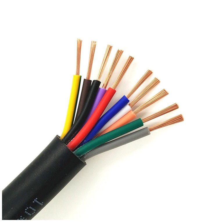
Pulling the wrong cable spec on a construction project — or worse, specifying unarmored cable in a trench alongside heavy machinery traffic — doesn’t just create a paperwork headache. It creates crushed insulation, ground faults, unplanned shutdowns, and in some cases a full cable replacement pull that costs three to five times what the original armor upcharge would have. Procurement managers feel this most painfully when a plant goes down mid-shift and the root cause traces back to a spec sheet someone treated as a formality.
Armored cable differs from standard cable by having one or more mechanical protection layers — typically steel wire armor (SWA) or steel tape armor (STA) — applied over the insulated cores. This construction resists crush loads, rodent damage, and abrasion in direct burial, industrial, and exposed runs where normal cable would fail. The armor adds roughly 15–30% to overall cable weight and typically 20–45% to unit cost, depending on conductor size, armor type, and applicable standard (IEC 60502, BS 5467, or AS/NZS 1429 being the most common).
What makes this choice genuinely tricky isn’t the obvious cases — no sane engineer runs unarmored cable under a forklift aisle. It’s the middle ground: cable trays with intermittent mechanical exposure, partial burial runs, or retrofit installations where the original installation environment has changed since the plant was built. Getting that call right, and understanding exactly what you’re paying for when the armor line item shows up on a quotation, is what the rest of this guide covers.
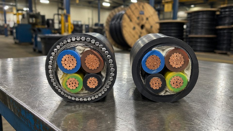
Layer-by-Layer Construction Breakdown: How Armored and Normal Cables Are Actually Built
Pull a standard unarmored power cable apart on the bench and you’re looking at a fairly predictable sequence of layers. Start at the center: a stranded copper or aluminum conductor, either bare or lightly tinned to improve termination reliability in humid environments. For medium-voltage (MV) cables — typically 6 kV and above — a semiconducting conductor screen sits directly over that conductor to smooth out electric field concentrations at strand surfaces. Then comes the primary insulation, either XLPE (cross-linked polyethylene, dominant in MV and increasingly in LV) or PVC (still common in cost-sensitive LV work and building wire). MV cables add a second semiconducting layer after the insulation — the insulation screen — before anything else happens. Below about 1 kV you usually skip both screens entirely.
Past the insulation, multicore cables need fillers — typically PP rope or extruded thermoplastic — to pack the interstitial gaps between cores into something approaching a round cross-section. A binder tape wraps the assembly. Then an inner sheath, usually PVC or LSZH compound, holds it all together before the outer jacket completes the run. That outer jacket, again PVC or LSZH depending on the project’s fire performance spec, is the only mechanical protection a standard unarmored cable gets.
That’s it. No hard layer, no crush resistance worth mentioning.
Where the Armored Cable Diverges
An SWA cable — steel wire armored, 600/1000V rated, the most prevalent armored type you’ll encounter globally — follows the same inner build through the inner sheath. Then two extra layers appear. First, the bedding: an extruded PVC or LSZH inner sheath that cushions the armor wires from the cable cores below. This layer matters more than it gets credit for. Without adequate bedding thickness and hardness, the armor wires can bite into the insulation under load cycling or installation tension. After bedding comes the armor itself: round galvanized steel wires, helically applied with a defined lay length. Over that, a final outer sheath — typically PVC ST2 compound or LSZH — seals and protects the armor from corrosion, UV, and whatever chemical environment the cable sits in.
Three layers become five. Weight goes up 15–30% depending on conductor size and core count, and cost goes up roughly 20–45% over an equivalent unarmored build. The exact premium depends on steel pricing, armor wire diameter (driven by cable OD), and whether you’re buying PVC or LSZH outer sheath.
Armor Type Variants and When to Specify Each
SWA works well for cables up to roughly 50 mm² and for routes with bends and directional changes — the round wires tolerate flexing during installation without cracking. For larger multicore cables on straight, fixed routes, STA (steel tape armor, two helically applied tapes with opposing lays) is often preferred by contractors because it’s easier to strip at terminations and handles radial crush loads well.
Single-core AC cables are a special case. Steel armor on a single-core cable creates a shorted magnetic circuit, generating eddy current losses that can be significant — I’ve seen this add meaningful heat on high-load circuits. AWA, aluminum wire armor, breaks that circuit. It’s the right call for single-core LV and MV cables where installation practice keeps all three phases together anyway.
DSTA, double steel tape armor, shows up in heavy industrial floors, road crossings, and anywhere a tracked vehicle or heavy trolley might roll over a cable route. It’s not a flexible-installation product; treat it as fixed, direct-buried or in-duct.
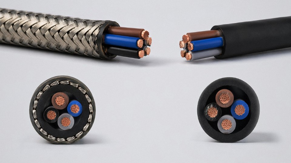
For mining trailing cables and similar continuously flexing applications, the armor layer is braided rather than helically wound — either galvanized steel braid or stainless for corrosive mine atmospheres. The bedding compound under braid armor needs to be softer and more resilient than standard bedding to prevent wire fatigue at the braid crossover points. Specify this explicitly in your datasheet if you’re going down that route, because a standard SWA bedding compound will not survive repeated coiling and uncoiling.
| Armor Type | Material | Typical Voltage Class | Best-Fit Application | Approx. Weight Penalty vs. Unarmored |
|---|---|---|---|---|
| SWA | Galvanized steel wire | Up to 33 kV | Multicore up to ~50 mm², flexible routes | +18–28% |
| STA | Two galvanized steel tapes | Up to 33 kV | Larger multicore, straight fixed routes | +15–25% |
| AWA | Aluminum wire | Up to 33 kV | Single-core AC cables, eddy loss–sensitive | +8–15% |
| DSTA | Double galvanized steel tape | Up to 11 kV (common) | High crush-load environments, road crossings | +22–32% |
| Braided steel/SS | Galvanized or stainless wire braid | Typically LV | Mining trailing, continuous-flex service | +12–20% |
Weight penalties vary with cable OD, conductor size, and armor wire count — a 4-core 16 mm² and a 4-core 240 mm² SWA cable sit at opposite ends of that range.
AWA (aluminum wire armor) is required for single-core AC cables to avoid eddy current heating losses that galvanized steel armor would cause.True
Steel is ferromagnetic; on a single-core cable carrying AC current, the helical steel armor forms a closed magnetic path around a single conductor, inducing circulating currents and adding heat load. Aluminum is non-magnetic and breaks this effect. IEC 60502 and most national utility specs flag this distinction explicitly.
Mechanical and Environmental Protection Ratings: What Armored Cable Actually Withstands
The protection ratings on a datasheet can look abstract until you’ve seen a direct-burial run chewed through by rats six months after commissioning, or watched a cable tray collapse onto an unarmored multicore and take out half a production line. These numbers exist for a reason. Understanding what they mean — and where they stop protecting you — is what separates a defensible cable specification from a guess.
Crush Resistance
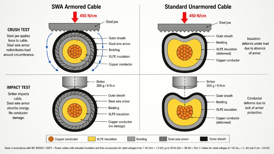
Per IEC 60502-1, SWA cables must survive a minimum crush force of 450 N/cm applied across the cable without damage to the insulation. Unarmored cables, depending on jacket compound and wall thickness, are typically rated somewhere in the 150–300 N/cm range — the spread depends on whether you’re looking at a thin PVC utility cable or a heavy-duty polyurethane-jacketed instrumentation cable. In practice, the difference matters most in cable trays and conduit runs where mechanical loads aren’t always predictable: settling backfill in direct burial, a forklift clipping an exposed surface run, conduit fittings that get overtightened. None of those scenarios are unusual. The steel tape or wire layer in SWA construction redistributes that load around the cable circumference rather than transmitting it straight to the insulation.
Impact Resistance
IEC 60502 Type II impact testing applies a 6 N·m blow with a 300 g striker, repeated multiple times, and the conductor must emerge without damage. Unarmored cables carry no equivalent mandatory requirement under the same standard. On a factory floor with overhead steel structures, steel fixings, and periodic maintenance traffic, that distinction is not trivial. An unarmored cable clipped to a cable ladder might survive years without incident, or it might take a single dropped wrench and fail intermittently in a way that’s genuinely difficult to trace.
Rodent Deterrence
This one doesn’t get enough attention in temperate climates, but in agricultural installations, subway infrastructure, and tropical regions it’s a documented and expensive failure mode. Rats and moles don’t chew through steel armor — not because they lack the motivation, but because they physically can’t get purchase on it. Unarmored cables rely entirely on jacket hardness, and no PVC or even HDPE jacket is a long-term match for persistent gnawing. A single rodent breach exposes the insulation, moisture follows, and you have an intermittent earth fault that shows up at 2 a.m. on a weekend.
Steel wire armored (SWA) cable provides effective physical deterrence against rodent damage in direct-burial and underground installations.True
The interlocked steel wire or tape layer cannot be breached by rodent gnawing, unlike plastic jacket materials. This is a recognized design advantage cited in cable engineering references for agricultural, subway, and tropical site applications.
Moisture and Water Ingress
Standard unarmored cables offer essentially no longitudinal water-blocking unless you specifically call it out in the specification — and many procurement teams don’t. Armored cables destined for direct burial or submarine runs are routinely built with filled stranding and longitudinal water-blocking tapes that meet IEC 60502-4 water penetration requirements. The filled stranding stops water wicking along the conductor interstices; the tape stops migration between the armor and the insulation screen. Leaving either out in a wet-trench application is a slow-motion failure you won’t see for a couple of years.
UV and Chemical Resistance
Outdoor armored cable jackets are generally compounded in HDPE or LSZH formulations rated for prolonged UV exposure and, in petrochemical or water-treatment environments, resistance to hydrocarbons and dilute acids. Standard indoor PVC jackets are not. PVC yellows, embrittles, and loses dielectric integrity under sustained UV — usually within two to four years of outdoor exposure, depending on climate and UV index. This isn’t a condemnation of PVC; it’s the right compound for what it’s designed to do.
Temperature Ratings
Both cable families use the same insulation compounds — PVC rated to 70 °C conductor temperature, XLPE to 90 °C — so the temperature rating itself isn’t where armored and unarmored cables diverge. The practical difference is that armored cables tend to be specified more consistently in industrial settings where ambient temperatures swing widely and thermal management is engineered into the installation design rather than assumed. Wide ambient swings matter because the current-carrying capacity calculation is sensitive to maximum ambient, and cable runs that look adequate at 25 °C can be marginal at 45 °C in a poorly ventilated plant room during summer.
| Hazard | SWA Armored Cable | Standard Unarmored Cable |
|---|---|---|
| Crush (IEC 60502-1) | ≥ 450 N/cm | 150–300 N/cm (jacket-dependent) |
| Impact (Type II) | 6 N·m, 300 g striker, pass required | No mandatory requirement |
| Rodent gnawing | Steel armor physically resists | Jacket hardness only — usually insufficient |
| Longitudinal water ingress | Blocked (IEC 60502-4 variants) | None unless specially specified |
| UV/chemical exposure | HDPE or LSZH outer jacket | Standard PVC — degrades outdoors |
The table above is a starting framework, not a substitute for reading the actual test reports for the specific cable construction you’re buying. Armor type, jacket compound, and filling all interact, and a cable described as “armored” on a datasheet can still fall short if the construction details don’t match the site hazard profile.
Installation Environments and Routing Methods: Where Each Cable Type Must and Must Not Be Used
The cable type you specify on a drawing means nothing if the routing method contradicts it. A lot of field substitution errors start exactly here — an unarmored cable gets pulled into a direct-burial trench because the armored stock was back-ordered, someone signs off, and eighteen months later a backhoe clips it or ground moisture works into the bedding layer.
Where Armored Cable Is Mandatory or Strongly Recommended
Direct burial without conduit is the clearest case. Trenched utility runs, agricultural irrigation feeds, and sub-road crossings all expose cable to compaction loads, rodent activity, and moisture cycling. SWA construction handles those stresses in ways a PVC-sheathed unarmored cable simply cannot. For any route that crosses under a road or railroad, most national standards either require armored cable or a rigid duct — and the duct itself needs to be rated for the overburden load, which often makes SWA direct burial the cheaper and faster option on shorter crossings.
Embedded-in-concrete runs are another non-negotiable. Once cable is encased, it’s essentially inaccessible without breaking structure. Armor protects against pour vibration, shrinkage cracking, and any future drilling that gets too close. Underground mine roadways add further hazard: roof falls, equipment contact, and the fact that access for repairs may be hours away. Offshore platform cable trays present a different set of problems — salt mist, personnel traffic, and the mechanical loads from cable movement in a seaway. Steel wire armor handles all of it; unarmored cable in those trays is a maintenance headache within a few years.
Industrial floor runs exposed to forklift or vehicle traffic are where I’ve seen the most avoidable damage in plant settings. Even if the cable is routed along a wall or in a surface trunking, a loaded forklift catching the edge of a conduit cover is a different kind of impact than anything an unarmored cable was tested against.
Where Unarmored Cable Is the Right — and More Economical — Choice
Enclosed building cable trays with no realistic mechanical damage risk don’t need armor. The tray itself provides support and reasonable protection; adding SWA here inflates material cost 20–45% and adds weight the tray structure may not have been designed for. Pulling cable through rigid steel conduit is the same logic: the conduit is the mechanical protection, and specifying armored cable inside it is double-dipping on cost without adding reliability.
Inside dry switchboards and electrical panels, armored cable creates termination complications — glands, shrouds, proper armor clamping — that slow down panel builds and create more potential leak points than they solve. Short indoor drops from ceiling to equipment, or branch circuits inside a conditioned facility, are correctly served by flexible unarmored cable.
The Transition-Point Problem
Hybrid routing is where specifications get sloppy. A cable specified as unarmored for an indoor tray run that then exits the building and drops into a direct-burial trench is a design error, not an installation option. The correct approach is either to switch to armored cable at the transition point (a gland and sleeve termination at the building wall penetration) or to carry rigid conduit all the way through the buried section. Half-measures — a loose wrap of corrugated conduit over an unarmored cable in a trench — routinely fail within three to five years.
Bending Radius and Support Spacing
These two factors don’t get enough attention at the drawing stage. SWA multicore cables typically require a minimum bending radius of around 12× the overall cable diameter; unarmored equivalents are usually 6–8× OD. That difference matters in junction boxes and termination cabinets, where available bend space is tight. A 35 mm² four-core SWA cable might have an OD of roughly 28–32 mm, putting the minimum bend at 336–384 mm — more than some cabinet depths allow.
Weight compounds the support issue. Armor adds roughly 15–30% to overall cable weight per meter, so vertical SWA runs in cable trays need support cleats at 350–500 mm intervals rather than the 450–600 mm typical for unarmored cables. Structural engineers calculating tray loads from a single-line diagram often miss this, particularly on retrofit projects where the tray was originally designed around unarmored cable.
IEC 60364-5-52, NEC Article 330, and AS/NZS 3008.1 each specify distinct installation and routing requirements that differentiate armored from unarmored cable applications.True
These are published, internationally recognized standards. IEC 60364-5-52 covers wiring system selection and installation; NEC Article 330 specifically addresses metal-clad cable routing and support; AS/NZS 3008.1 governs cable selection for Australian and New Zealand electrical installations including burial depth and mechanical protection requirements.
Ignoring those standards during specification isn’t just a compliance risk — it’s a procurement risk, because many project owners and EPC contractors now require standard compliance documentation before accepting cable submittals. Specifying the wrong type for the routing method can trigger a full re-submission cycle and delay material release by weeks.
Electrical Performance Differences: Impedance, Capacitance, Eddy Currents, and EMI Shielding
Most procurement conversations about armored versus normal cable stop at mechanical protection. That’s understandable — the crush ratings and installation environments are visible, tangible differences. But the armor layer also changes the cable’s electrical behavior in ways that bite engineers who don’t account for them during design, and the consequences range from nuisance tripping to a genuine fire risk.
Impedance and Earth Fault Loop Calculations
Steel wire armor isn’t just a mechanical shell. It’s a conductor — a poor one, but a conductor nonetheless — and it runs the full length of the circuit in intimate contact with the outer sheath. On multi-core SWA cables, this creates a parallel return path that slightly reduces positive-sequence impedance. The effect is modest, typically a few percent, but in fault calculations per IEC 60909 it has to be accounted for. Protection relay engineers specifying overcurrent settings on LV distribution feeders sometimes find that the armor’s contribution to the earth fault loop impedance is just significant enough to affect the disconnection time calculation under TN-S or TN-C-S earthing arrangements. Miss it and your upstream breaker may not clear a line-to-earth fault within the time limits set by IEC 60364-4-41. That’s not a theoretical concern — it’s the sort of thing that shows up during commissioning testing when the loop impedance reading comes back lower than the design sheet predicted.
Eddy Current Losses in Single-Core Cables: The Steel Armor Problem
This is where armored cable selection genuinely gets complicated. When you run a single-core AC cable with steel wire armor, the alternating magnetic field from the conductor induces circulating currents in the armor. Those currents dissipate as heat. Depending on cable size and load, this can raise the cable’s operating temperature by roughly 5–15 °C and reduce usable current-carrying capacity by somewhere between 10 and 20% compared to an otherwise identical cable with aluminum wire armor (AWA) or no armor at all. The exact penalty depends on conductor cross-section, load power factor, and whether the armor is bonded at one or both ends.
This is why, above approximately 95 mm² on single-core AC cables, AWA is the standard choice rather than SWA. Aluminum has much lower magnetic permeability, so eddy current induction is dramatically reduced. Specifying SWA on a 240 mm² single-core LV feeder isn’t just inefficient — you’re effectively derating the cable and baking heat into a trunking system that the thermal design didn’t budget for.
Steel wire armor on single-core AC cables above 95 mm² significantly reduces current-carrying capacity compared to aluminum wire armor.True
Steel's ferromagnetic properties cause substantial eddy current losses in single-core AC cables; aluminum wire armor avoids this because aluminum is non-magnetic, which is why international standards and cable manufacturers' derating tables show lower ampacity for SWA versus AWA in large single-core configurations.
Capacitance and Charging Current on Long MV Runs
The armor layer sits close to the insulation. That proximity — combined with the semiconducting bedding layer on MV cables — increases the effective capacitance per unit length, typically adding something in the range of 0.2–0.5 µF/km over an equivalent unarmored cable, though the actual figure depends on insulation thickness, conductor diameter, and armor configuration. On a short LV feeder, nobody cares. On a 10 km medium-voltage underground run at 11 kV or 33 kV, the charging current drawn by that capacitance becomes a real number you have to subtract from the circuit’s usable load current. In some cases on long MV cables, charging current can consume 5–12% of rated thermal capacity before a single ampere of load current flows. This is exactly why MV cable sizing calculations for extended underground distribution runs need the manufacturer’s actual published capacitance figure, not a generic estimate.
EMI Shielding Effectiveness
A continuous metallic armor layer provides meaningful electromagnetic shielding — typically 30–40 dB of attenuation when measured per IEC 62153-4-3 methodology. In practice, that’s enough to make armored cables a reasonable choice for instrumentation signal runs through electrically noisy environments: variable-speed drive panels, resistance welding stations, large transformer bays. An unarmored, unscreened cable in the same environment offers essentially zero attenuation. That said, armor is not a substitute for a purpose-built screened instrumentation cable where signal integrity below a few millivolts matters. The shielding effectiveness of armor is good enough for power circuits and moderate-sensitivity analog signals, but for thermocouple extension leads or 4–20 mA loops running close to high-frequency switching equipment, a dedicated foil-and-braid screen is still the right answer.
Bonding the Armor as a Protective Conductor
The armor’s role as a circuit protective conductor (CPC) only works if it’s correctly bonded and earthed. For multi-core SWA cables, IEC 60364-5-54 and BS 7671 require the armor’s cross-sectional area to meet minimum CPC sizing rules — and in most practical LV cable sizes, standard SWA armor passes this check, eliminating the need for a separate earth conductor and simplifying installation. Single-core cables are a different story: bonding both armor ends creates a closed loop that maximizes eddy current losses, while bonding only one end limits those losses but also limits the armor’s fault current carrying capacity. The engineering trade-off has to be made explicitly during design, not left to the installation crew to decide on site.
International Standards, Testing Requirements, and Certification Marks That Govern Both Cable Types
Specifying “armored cable to IEC standard” in a purchase order is not enough. I’ve seen entire cable shipments rejected at site acceptance because the supplier delivered product built to IEC 60502 while the project’s electrical inspector required BS 5467 — two standards that look similar on the surface but differ in armor wire diameter tolerances, oversheath thickness minima, and marking requirements. Getting this right before you issue the RFQ saves weeks.
The Core IEC Standards and What Each Actually Covers
IEC 60502-1 is the workhorse for low-voltage power cables up to 1 kV — both armored and unarmored — and it’s where most industrial procurement specs should start. It covers conductor construction, insulation materials, bedding, armor (steel wire and steel tape), and oversheath. IEC 60502-2 picks up from there for medium-voltage cables in the 1–30 kV range; if you’re buying 11 kV SWA feeders for a substation, this is the document your factory acceptance test (FAT) protocol should reference, not Part 1.
IEC 60227 applies to the lighter, PVC-insulated cables — the kind you’d find in panel wiring or light fixed installations — and IEC 60245 covers rubber-insulated cables, including flexible types used on mobile equipment or in high-temperature environments. Neither of those two standards has meaningful armor provisions; they’re essentially the unarmored world.
Regional Variants That Catch Buyers Off Guard
BS 5467 is the UK derivative for armored LV cables and is still the default reference on projects following British engineering practice — common in the Middle East, parts of Africa, and legacy Commonwealth infrastructure. It aligns broadly with IEC 60502-1 but specifies slightly different armor wire diameters for given cable sizes and has specific marking requirements. Supplying an IEC 60502-1 cable on a BS 5467 spec without a formal equivalency statement from the engineer of record is a compliance risk.
AS/NZS 1429 governs Australian and New Zealand armored power cables. Voltage class definitions differ from IEC — what IEC calls 0.6/1 kV, AS/NZS designates as 0.6/1 kV as well, but the construction details around bedding and oversheath thickness diverge enough to matter on a tight audit.
In Europe you’ll still encounter NF C 32-321 (French) and VDE 0276 (German) on older project specs or when supplying into those domestic markets. North America is its own regime entirely. ICEA S-94-649 and UL 1569 govern MC (metal-clad) cable, which is the rough functional equivalent of SWA cable in NEC-jurisdiction projects, but the construction is different — interlocked aluminum armor rather than helically wound steel wires — and the NEC Article 330 installation rules are not interchangeable with IEC installation guidance. Assuming IEC compliance satisfies NEC requirements is a mistake that gets caught during rough-in inspection, not at the procurement desk.
Type Tests That Apply Only to Armored Cable
This is the section most RFQs skip, and it’s where supplier differentiation actually lives. IEC 60502-1 requires armored cables to pass a crush test (Clause 18.4), an impact test (Clause 18.5), and — for flexible armored types — a repeated bending test (Clause 18.6). An armor continuity test verifies that the armor layer provides an unbroken low-resistance path for fault current, which matters directly for protection relay coordination. Unarmored cables are not required to pass any of these.
A cable labeled 'armored' that cannot produce a third-party crush and impact test report to IEC 60502-1 Clause 18.4 and 18.5 should not be accepted on a project where mechanical protection is the reason armor was specified.True
Clause 18.4 and 18.5 are mandatory type tests for armored cables under IEC 60502-1. Without documented test results from an accredited lab, there is no verified basis for the mechanical protection claims.
Routine and Sample Tests Applicable to Both Types
Every cable shipment — armored or not — should arrive with routine test documentation covering conductor resistance per IEC 60228, insulation resistance, and AC high-voltage withstand. For medium-voltage cables, partial discharge testing is a sample test requirement under IEC 60502-2 and is a meaningful indicator of insulation void quality. These are not optional extras; they are the minimum you should expect in a material test report (MTR).
What to Actually Demand From Suppliers
Ask for test reports issued by accredited third-party laboratories — CPRI, KEMA, UL, SGS, or equivalent bodies recognized in your jurisdiction. Factory production control (FPC) certificates demonstrate that the manufacturing process is audited, not just the finished product. For cross-border procurement, country-of-origin declarations have become commercially critical; several markets have active anti-dumping duties on cable from specific origins, and a vague declaration creates customs exposure downstream.
Jinda’s product range — covering both armored and unarmored cables — holds CCC (China Compulsory Certification), CE marking, SASO certification for Saudi Arabia, and additional approvals that vary by product family. When requesting a quotation for an export project, specifying the destination country upfront allows the correct certification package to be confirmed before order placement rather than after.
Total Cost of Ownership Analysis: Purchase Price, Installation Labor, and Lifecycle Cost Compared
The purchase price comparison is where most procurement decisions go wrong. An engineer sees the per-meter price of SWA cable, compares it to an unarmored equivalent, and logs the armored option as the expensive choice. That instinct is understandable — and on a purely material basis, it’s not wrong. But it only looks at one line item in a cost model that has five or six.
Material Cost: The Starting Point, Not the Whole Story
SWA armored cable genuinely does cost more per meter. For a 4-core 16 mm² Cu/XLPE/SWA/PVC 0.6/1 kV cable — one of the most commonly specified utility and industrial distribution cables globally — 2024 export market pricing runs roughly USD 4.50–6.50/m armored versus USD 3.00–4.20/m for an unarmored equivalent in the same conductor size and insulation class. That spread narrows on larger conductors where copper dominates the price, and widens on smaller sizes where the armor layer represents a higher share of total material cost. Copper market volatility in any given quarter can shift both figures by 10–15%, so treat any benchmark as directional rather than fixed.
The 25–45% price premium on armored cable is real. What changes is whether it matters once you account for what you’re replacing.
Where Installation Cost Flips the Equation
Direct burial is the scenario that most reliably makes armored cable the cheaper option on total installed cost. Unarmored cable in a buried run requires rigid conduit protection — typically GRC (galvanized rigid conduit) or HDPE duct — and in rocky or root-heavy ground, conduit installation alone can run USD 8–20/m installed when you factor in trenching difficulty, fittings, and pulling labor. In straightforward soil conditions the number is lower, maybe USD 5–10/m, but it’s never zero.
SWA cable buried directly at correct depth eliminates that conduit cost entirely. On a 500 m feeder run across a site with mixed terrain, the conduit saving alone can exceed the armor premium by a factor of two or three. In practice, the break-even point on a direct-burial run is usually somewhere between 80 and 200 meters depending on ground conditions and local labor rates — beyond that, armored cable is the economically rational choice even before you consider failure risk.
Termination Costs Are Real, Especially at Scale
This is one people forget. SWA cables need proper cable glands with armor clamp rings — brass glands for standard industrial environments, stainless for coastal or chemical exposure. Per gland, you’re looking at roughly USD 8–40 depending on cable diameter and material, plus the bonding conductor and label. An unarmored cable uses a standard cable gland or cord grip that might cost USD 2–8. On a panel with 12 incoming SWA cables, that’s perhaps USD 200–400 in additional gland hardware plus maybe an hour of extra labor per termination for a careful sparky who’s doing the armor bond properly.
Scale that to a substation fit-out with 200 SWA terminations, and the delta is non-trivial — potentially USD 8,000–15,000 in termination hardware alone, depending on gland sizes and specification. That number should be in your project budget, not discovered during procurement.
Failure and Repair: The Cost Nobody Budgets Until It Happens
A buried unarmored cable hit by an excavator, ground settlement, or rodent activity is a project in itself to repair. Excavation, fault location, splice repair or full section replacement, re-burial, and surface reinstatement — in a paved industrial yard or road crossing, that’s typically USD 5,000–50,000 per incident. The wide range reflects depth, surface type, and whether you’re cutting through concrete or asphalt versus open ground. Add production downtime if the cable feeds a process load, and you can multiply that figure quickly.
Armored cable doesn’t make mechanical damage impossible, but it reduces the probability dramatically. One avoided excavation repair on a medium-depth buried run in a trafficked area will often pay for the armor premium across an entire cable order.
Properly installed SWA armored cable has a design life of 30–40 years in direct burial or industrial environments.True
This is consistent with IEC 60502 design intent and widely cited in utility and industrial cable engineering references, assuming correct installation depth, proper backfill, and adequate drainage. Actual service life depends on soil chemistry, thermal cycling, and installation quality.
Unarmored cable in equivalent mechanical exposure — where it survives at all — realistically needs replacement in 10–15 years. Over a 40-year asset life, that means two or three full cable replacements including all the associated installation cost. The total lifecycle cost of the “cheaper” cable can easily run two to three times the armored option.
Decision Framework: When Armor Is Worth It and When It Isn’t
Not every cable run needs armor. A short indoor run in cable tray inside a clean panel room, protected from any mechanical contact, is a case where unarmored cable is perfectly adequate and specifying SWA would be over-engineering. The question is always about exposure.
| Environment / Condition | Mechanical Risk | Recommended Choice |
|---|---|---|
| Direct burial, open ground | High | SWA armored |
| Direct burial, road or paved crossing | Very high | SWA armored (consider double layer) |
| Indoor cable tray, low traffic area | Low | Unarmored acceptable |
| Industrial floor level, forklift exposure | High | SWA or heavy conduit |
| Overhead rack, clean environment | Low | Unarmored acceptable |
| Outdoor above-ground, UV + impact risk | Medium–high | Armored or conduit system |
| Coastal / chemically aggressive soil | High | SWA with appropriate sheath |
The honest rule of thumb: if a failure in that cable run would cost more than USD 3,000–5,000 to repair and restore, the armor premium almost certainly pays for itself. Budget constraint is a real factor, but it should be weighed against failure probability and consequence — not just against the line-item material price.
Selecting the Right Armored Cable Specification: A Step-by-Step Guide for Project Engineers
Getting the construction breakdown right is only half the job. Translating that knowledge into a purchase order that actually delivers the correct cable — first time, without factory clarifications that stall your schedule — requires a disciplined specification sequence. Miss one input and you may end up with the right armor type on the wrong sheath compound, or the correct conductor size paired with an insulation class that fails its voltage withstand test on arrival. Here is the workflow I’d walk through on any serious project.
Step 1 — Define the Electrical Duty First
Before anything else, nail down system voltage (LV 0.6/1 kV, MV 6/10 kV, 12/20 kV, or 18/30 kV), full-load current, and prospective fault level. These three parameters drive conductor cross-section, insulation thickness, and screen design. Also confirm whether the circuit is single-phase, three-phase, or DC — a point that sounds obvious but is frequently left ambiguous in early RFQs, and DC circuits have different insulation stress requirements that some engineers forget to flag. Conductor size on LV copper typically runs 1.5 mm² up to 630 mm²; aluminum can push to 1000 mm² on SWA designs where weight and cost matter more than conductivity margin.
Step 2 — Characterize the Installation Environment Honestly
Produce a site hazard checklist before you touch the catalog. Cover burial depth and backfill type, soil resistivity (anything below roughly 10 Ω·m should be treated as aggressive — coastal reclaimed land and industrial fill often hits this), presence of hydrocarbons or chemical runoff, ambient temperature extremes at both ends, UV exposure duration, and confirmed rodent or termite pressure. This step determines your outer sheath compound and whether single armor is sufficient or you need a double-steel arrangement. Skipping this is how projects in tropical coastal zones end up with standard PVC-sheathed SWA that begins corroding within two or three wet seasons.
Step 3 — Select the Armor Type Against a Clear Decision Rule
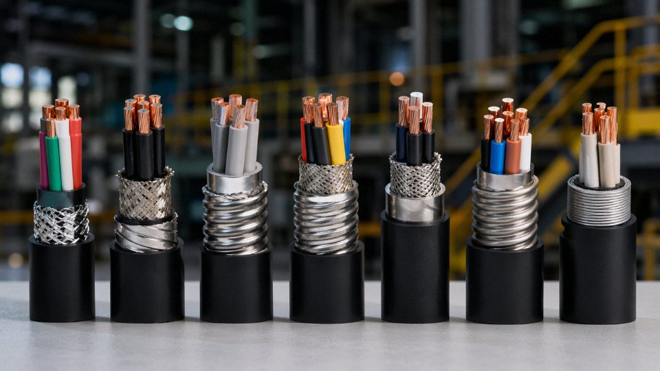
The logic is fairly straightforward once you have the site data: single-core AC cables above 95 mm² should use aluminum wire armor (AWA) to avoid the induced circulating current losses that steel wire creates in single-core AC circuits. Multicore LV runs with complex routing or significant mechanical hazard — go SWA. Large multicore LV on straight, rigid routes where installation is controlled: steel tape armor (STA) is lighter and cheaper. Where the highest crush resistance is the overriding concern, double steel tape armor (DSTA) is the answer. Flexible reeling applications on mining equipment or cable reels need braided steel armor, which tolerates repeated flex cycles that would fatigue conventional wire or tape constructions quickly.
Step 4 — Specify the Outer Sheath Compound
PVC is cost-effective and fine up to roughly 70 °C continuous ambient — adequate for most general industrial and utility work. HDPE outperforms it in direct burial with chemical exposure. LSZH is mandatory in confined spaces: tunnels, data centers, public transit infrastructure, anywhere smoke toxicity and halogen acid generation during a fire are regulated. EPR sheaths handle high-temperature and oilfield environments where conventional thermoplastics soften or crack. Matching compound to environment is not conservative over-engineering; it is the difference between a 30-year service life and a re-pulling job at year eight.
Step 5 — Confirm Standards and Required Approvals
State the exact standard number and amendment: for example, IEC 60502-1:2004 + AMD1:2016, not just “IEC 60502.” List destination-country certifications explicitly. Add any project-specific tests — a cold-bend test at −15 °C is a reasonable requirement for Nordic or high-altitude installations, and some petrochemical projects mandate additional hydrocarbon immersion tests not covered in base standards.
IEC 60502, BS 5467, and AS/NZS 1429 are the three most widely cited international standards governing armored power cable construction globally.True
These standards are referenced across utility, industrial, and infrastructure projects in Europe, the Middle East, Australia, and Southeast Asia, and are routinely specified in international project tender documents for armored LV and MV cable.
Step 6 — Issue a Complete Cable Schedule, Not a Vague Description
A proper RFQ includes conductor material (Cu or Al), conductor class (solid Class 1, stranded Class 2, or flexible Class 5 per IEC 60228), number of cores, cross-sectional area, color code standard applicable to the destination country, drum length tolerance (±5% is typical, but confirm if your cut lengths are tight), reel type, and the exact test documentation required — routine test certificates at minimum, type test reports if the project demands them. Leaving any of these fields blank invites the manufacturer to default to whatever is simplest to produce, which may not be what you need. Jinda’s technical team maintains pre-filled cable schedule templates for common project types — utility distribution, industrial plant, subsea duct — which cuts the back-and-forth considerably on first orders.
Frequently Asked Questions About Armored Cable vs. Normal Cable
Can I use armored cable indoors in a cable tray instead of conduit?
Yes, and on many projects it’s the smarter choice. SWA or STA cable laid in an indoor cable tray is fully compliant under IEC 60364-5-52 and eliminates both the material cost of conduit and the labor to pull cable through it. The catch most engineers overlook is tray loading. Armored cable runs roughly 15–30% heavier per meter than an unarmored equivalent of the same conductor size — that differential adds up fast on a 50-meter horizontal run with 20 circuits. Check the tray manufacturer’s deflection and load ratings before you commit. Gland selection matters too: every enclosure entry needs a correctly sized armor gland that mechanically clamps the armor wires and provides a low-impedance bonding path to the panel earth bar. A loose or wrong-type gland doesn’t just risk an earth fault — it can cause armor corrosion and intermittent continuity that’s a nightmare to trace later.
Is the steel wire armor a reliable earth conductor?
In most jurisdictions, yes. IEC 60364 and BS 7671 both permit SWA armor to function as the circuit protective conductor (CPC), provided the armor’s cross-sectional area satisfies the adiabatic equation for the specific circuit’s prospective earth fault current and maximum disconnection time. Don’t assume it’s adequate just because the cable passed factory testing. Run the calculation — a 1.5 mm² two-core SWA feeding a 32 A circuit over 80 meters may not have enough armor CSA to clear a fault in time, depending on upstream protection. If the numbers are borderline, run a separate earth conductor rather than argue about it during a commissioning inspection.
SWA armor can legally serve as the circuit protective conductor under IEC 60364 and BS 7671 when its cross-sectional area meets the adiabatic equation for the circuit's fault current and disconnection time.True
Both IEC 60364-5-54 and BS 7671 Section 543 explicitly permit the use of armor as a CPC subject to verification against the adiabatic equation (S ≥ √I²t / k), which accounts for fault current magnitude, disconnection time, and the armor material's thermal constant.
Why does single-core armored cable use aluminum wire armor instead of steel?
Steel armor on a single-core AC cable forms a closed ferromagnetic loop around the conductor. That loop sees the full alternating magnetic field from the conductor current, which induces eddy currents and hysteresis losses severe enough to meaningfully reduce current-carrying capacity and generate localized heat. Aluminum is non-ferromagnetic — it simply doesn’t close that magnetic circuit the same way. AWA (aluminum wire armored) single-core cables carry their full rated current without a de-rating penalty. Specify steel armor on single-core AC cable and you’ve essentially self-imposed a current de-rating you didn’t budget for. It’s a surprisingly common spec error on first-time projects.
What is the difference between SWA and XLPE SWA?
SWA describes only the armor layer. XLPE SWA tells you both the insulation compound (cross-linked polyethylene) and the armor type. The insulation distinction matters operationally: XLPE carries a 90 °C maximum conductor temperature rating versus 70 °C for PVC-insulated SWA. That translates to higher current capacity for the same conductor size, better resistance to thermal aging over a 30–40 year service life, and improved performance under short-circuit conditions. On a congested cable tray where de-rating factors already bite into capacity, the difference between 70 °C and 90 °C insulation can determine whether you specify 95 mm² or 70 mm² conductors — a meaningful cost and weight difference across a large installation.
How do I terminate an SWA cable to ensure the armor is properly earthed?
Use a gland type matched to the cable’s outer sheath: a CW-type gland for cables with a PVC oversheath, a BW-type for bare armor. The gland works by clamping the armor wires between a back nut and a cone as you tighten up, creating mechanical grip and electrical continuity simultaneously. Once the gland is fitted, connect its earth tag or the gland body itself to the equipment earth bar with a bonding conductor sized in accordance with IEC 60364-5-54. Never leave armor floating, and never rely on the gland body making incidental contact with a painted enclosure knockou — paint is not a conductor. In practice, a quick continuity check between armor and earth bar after termination takes 30 seconds and catches most installation errors before they become fault events.
Can armored cable be directly buried without sand bedding or a duct?
Technically, yes — SWA and STA cables are designed for direct burial. Practically, best practice under IEC 60364-5-52 and most national grid codes calls for a 75–100 mm bed of selected sand or fine screened soil beneath the cable and the same depth above it, followed by a warning tile or marker tape laid 150–200 mm above the cable crown. Skipping bedding doesn’t void the cable’s rated performance on day one, but over a 30–40 year life, a sharp stone working into the backfill under seasonal ground movement can eventually breach the outer sheath and initiate corrosion or insulation damage. The sand costs almost nothing relative to a cable replacement excavation.
Does armored cable provide fire resistance?
Standard SWA does not. The steel armor protects against mechanical damage, not fire. In a sustained fire, the PVC or standard LSZH outer sheath will ignite, and circuit integrity will be lost. Fire-resistant armored cable is a separate product category — these cables incorporate mica-tape wrapping beneath a fire-resistant insulation compound and are tested to maintain circuit integrity at temperatures of 830–950 °C for 60–120 minutes, depending on the specification (BS 8519 Category C or IEC 60331 compliance are the most commonly referenced benchmarks). If you’re routing emergency lighting, fire pump feeders, or smoke control circuits, specify fire-resistant armored cable explicitly. “Armored cable” alone on a drawing or purchase order will not get you there.
Why Cable Manufacturer Experience and Supply Chain Depth Matter More Than Price Per Meter
Price per meter is an easy number to compare on a spreadsheet. What it doesn’t tell you is whether every drum in your order was drawn from the same copper rod batch, tested on the same calibrated equipment, and armored to the same lay-length tolerance. For a single-building commercial fit-out, that probably doesn’t keep you up at night. For a 40-km offshore wind array or a multi-voltage petrochemical plant where protection relays are set to trip on conductor impedance thresholds, it absolutely should.
Conductor Consistency Across a Full Cable Schedule
One of the less-discussed failure modes in large projects is mismatched electrical characteristics between drums that nominally carry the same part number. A manufacturer with 36 years of continuous production, ISO 9001-certified lines, and in-house conductor drawing can typically hold conductor DC resistance variance within roughly ±1% across an entire lot. A procurement team that spot-buys from three or four low-cost trading companies to hit budget — each sourcing finished cable from different sub-suppliers in different provinces — may receive drums whose actual conductor resistance varies by 3–5% or more, even at the same nominal cross-section.
That variance matters when your protection engineer has set earth-fault relay pickup based on calculated loop impedance. Enough spread across a long feeder and you’re either looking at nuisance trips or, worse, genuine faults that don’t clear fast enough. I’ve seen relay coordination reports reissued mid-construction because the cable batch data didn’t match the original spec assumptions. That’s not a cheap problem.
Vertical Integration Is a Quality Argument, Not Just a Marketing One
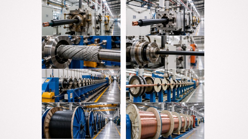
Jinda’s five production bases in China span the full process: copper rod breakdown, wire drawing, stranding, insulation extrusion, bedding, armoring, outer sheath extrusion, and drum winding. Every stage operates under a single quality management system, which means traceability runs from the raw copper or aluminum input right through to the finished drum label and drum card.
When those stages are split across multiple independent suppliers — as they often are with trading companies — you get inter-supplier hand-off gaps. The bedding extruder doesn’t know what the armoring line’s tension settings are. The test certificate at the end reflects the finished product, but nobody holds end-to-end accountability for how it got there. In practice, that shows up in subtle ways: inconsistent armor lay, slightly oval conductor bundles, bedding that’s marginally thinner at one end of a long drum. None of it necessarily fails a routine test, but it accumulates as lifecycle risk.
Custom Constructions for Non-Catalog Projects
Large international projects — a data center campus, a petrochemical plant expansion, an offshore substation export cable system — routinely require constructions that aren’t in any standard catalog. A 20 kV XLPE armored LSZH cable with longitudinal water-blocking tape and a specific armoring configuration for a particular burial depth isn’t something a trading company can quote with engineering confidence. A manufacturer with a dedicated R&D function can typically develop, prototype, and qualify a special construction in roughly 8–12 weeks, depending on material lead times and whether third-party type-testing is required. That timeline compresses significantly if the base construction is already proven and only the outer geometry or sheath compound is being modified.
Jinda can develop and qualify special cable constructions for international projects within 8–12 weeks.True
This is consistent with the manufacturer's stated R&D capability and reflects realistic timelines for custom cable qualification when base materials and test facilities are already in-house.
Export Certification Is Harder Than It Looks
Serving buyers in more than 50 countries means navigating a genuinely complex matrix of destination-specific certifications. SASO for Saudi Arabia, SIRIM for Malaysia, SNI for Indonesia, NOM for Mexico — each has distinct documentation requirements, test report formats, and sometimes specific local-language labeling rules. A procurement team that assumes CE marking is sufficient for a Southeast Asian infrastructure tender will discover the gap at customs clearance, not before. Verifying that your cable supplier can deliver the exact certification package required by the destination country before placing the order is basic due diligence that frequently gets skipped under schedule pressure.
After-Sales Support During Commissioning
Armored cable doesn’t end at the drum. Termination and jointing on SWA or AWA cables require specific gland selections, correct armor bond arrangements, and in some cases manufacturer-specific jointing kits. A manufacturer that can provide detailed jointing instruction documents, coordinate third-party training for the site contractor, and deploy technical support to a project site for large or complex installations takes a meaningful slice of commissioning risk off the table. That kind of support doesn’t show up in the per-meter price comparison, but it shows up clearly when a contractor is troubleshooting a failed joint at 2 AM during cable pressure testing.