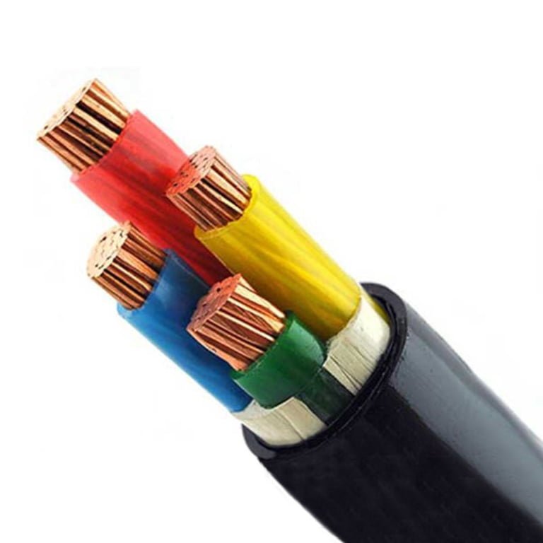
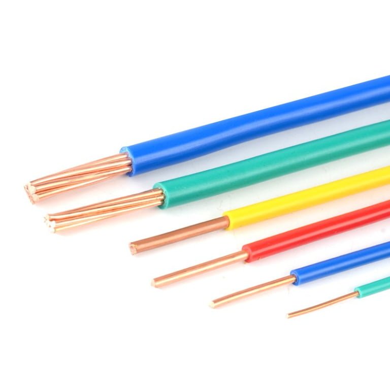
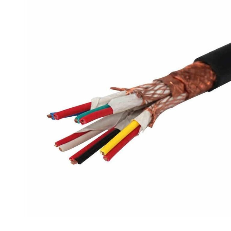
Specifying the wrong armoured cable isn’t just a paperwork error — it causes real failures. Undersized armour gets crushed by backfill settlement or mechanical handling; the wrong armour material corrodes in months in wet or chemically active ground; PVC-insulated cables run too hot in tightly bundled trays and shed years off their rated service life. Any one of those failures means unplanned downtime, excavation costs, or a re-pull that can easily run to several times the original cable budget.
The armour type you need depends on four things: installation method (direct burial, cable tray, duct, aerial), mechanical threat level, conductor material, and the presence of AC interference — which is why aluminium wire armour (AWA) is standard for single-core AC cables, steel wire armour (SWA) is the default for multi-core buried runs, and XLPE insulation is the right call wherever operating temperatures or short-circuit ratings are the binding constraint.
What most procurement specs get wrong is treating armour type as a single checkbox rather than the intersection of at least four independent variables — and the combinations matter more than any one factor alone. The following sections break each decision point down the way a cable engineer would: by installation environment first, then mechanical load, then electrical constraints, with enough practical detail to let you write a defensible specification or challenge one that’s been handed to you.
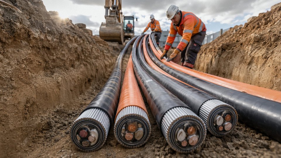
Steel Wire Armour (SWA) vs. Steel Tape Armour (STA): Matching Mechanical Protection to Installation Stress
These two constructions look similar on a datasheet and get confused more often than they should. Getting them mixed up doesn’t just mean a specification error — it can mean cable damage within months of commissioning, failed third-party inspections, or a warranty argument nobody wants to have.
How SWA Is Built and Where It Belongs
Steel Wire Armour is exactly what it sounds like: individual galvanised steel wires wound helically around the cable core, over an inner sheath, in a single layer. Wire diameters run from roughly 0.8 mm on smaller distribution cables up to 3.15 mm on heavy power cables — the actual diameter depends on cable OD and the tensile load the armour needs to carry per IEC 60502-2. The helical lay gives SWA its defining characteristic: genuine tensile strength. You can pull it, hang it vertically, run it down a mine shaft or through a steep trench without the armour unravelling or the conductor pack shifting inside.
Direct burial is the classic SWA application. Per IEC 60502-2 and BS 5467, SWA cables are rated for burial at 0.5–1.2 m in standard soil — the actual required depth depends on voltage level, soil type, and whether there’s a concrete tile protection layer above. In a quarry, a petrochemical plant, or anywhere cables cross under roadways, SWA earns its cost premium. The crush and impact resistance is real, though it isn’t infinite; a direct hit from a mechanical excavator will still cause damage, which is why marker tape and route documentation matter even with armoured cable.
How STA Is Built and Where It Belongs
Steel Tape Armour uses two galvanised steel tapes wound concentrically around the inner sheath, each with a minimum 50% overlap so there’s never a gap in coverage. The tapes are typically 0.2–0.5 mm thick. What you gain is hoop strength — resistance to radial crush — rather than tensile load capacity. What you give up is flexibility and pull-through capability.
STA is well-suited to cables installed in ducts, conduit systems, or cable trays where the route is relatively straight and the cable won’t experience axial tension during or after installation. Multi-core cables in building services, substation feeders running in organised tray systems, and cables pulled through short duct runs are all reasonable STA territory. The tape construction also makes STA cables somewhat easier to terminate in the field, since there’s no loose wire layer to deal with — a practical point that electricians working in tight switchgear enclosures will appreciate.
SWA vs. STA: Side-by-Side
| Property | SWA | STA |
|---|---|---|
| Tensile / pull-through strength | High | Low — not suitable for vertical runs |
| Radial crush resistance | Moderate–high | High (hoop strength from tape overlap) |
| Flexibility | Better, handles bends in routed installations | Stiffer; minimum bend radius is larger |
| Weight added to cable | Higher (solid wire mass) | Lower |
| Corrosion risk | Lower (thicker galvanising on wires) | Slightly higher if tape edges aren’t sealed |
| Direct burial suitability | Yes, per IEC 60502-2 / BS 5467 | Generally not recommended |
| Typical environments | Trenching, mining, industrial plant, underground | Duct, tray, indoor substation, short conduit runs |
The Single-Core Problem With SWA
Large-diameter single-core cables on AC systems almost never use SWA, and this catches people out. A continuous steel wire armour layer forms a closed magnetic circuit around a single AC conductor. That induces circulating currents in the armour, which means resistive heating, energy loss, and potential overheating under load — the problem scales with cable size and current. For single-core cables, the standard solution is Aluminium Wire Armour (AWA), which breaks the magnetic circuit because aluminium’s permeability is effectively non-magnetic. Any specifier putting SWA on a large single-core MV feeder should revisit that decision before the cable is manufactured.
Standards Compliance and Production Reality
Both IEC 60502-2 and BS 5467 define armour construction requirements — wire diameter ranges, tape thickness and overlap, tensile test loads, and galvanising quality. They’re not identical standards and some export projects require dual compliance on the same cable. Jinda’s production lines are configured to accommodate both, which matters when a project spec calls out BS 5467 for UK-origin documentation but the cable ships to a Southeast Asian site where IEC 60502-2 is the local inspection standard.
Jinda produces SWA and STA cables compliant with both IEC 60502-2 and BS 5467 from the same production familyTrue
Dual-standard compliance on a single product family requires controlled raw material selection (wire diameter tolerances, tape thickness, galvanising specification) and documented test procedures for both standards — this is a legitimate manufacturing capability for established producers serving international export markets, not a generic marketing claim.
Aluminium Wire Armour (AWA) and Aluminium Tape Armour (ATA): When to Choose Non-Magnetic Armour
The single most common armour specification error I see in MV cable projects is running single-core AC cables with steel wire armour. It looks like a reasonable choice on paper — SWA is familiar, strong, and widely stocked. In practice, it can cause enough heat and energy loss to be a genuine operational problem within months of commissioning.
The Electromagnetic Case Against Steel on Single-Core AC Cables
Steel is ferromagnetic. Wrap it helically around a single-core cable carrying alternating current and you create a near-closed magnetic circuit around a conductor that produces a continuously alternating field at 50 or 60 Hz. The armour wires act as a shorted turn in a transformer. Eddy currents circulate in the steel, generating heat — and in cables above roughly 1 kV at full load, that heating can be severe enough to push conductor temperatures beyond the cable’s continuous rating, accelerate insulation ageing, and produce measurable watts-per-metre losses that compound across a long run.
Aluminium is non-ferromagnetic. Its relative permeability is effectively 1, so the induced circulating currents are far lower in magnitude, and the I²R losses in the armour itself remain small. For any single-core cable operating on AC at rated voltages above 1 kV — whether that’s a 6 kV feeder in a utility substation or a 33 kV circuit in a large commercial building ring main — aluminium armour is essentially mandatory from an electrical engineering standpoint. This isn’t a preference; it’s physics.
Steel wire armour on single-core AC cables above 1 kV creates circulating eddy currents that cause unacceptable heating and power loss, making aluminium armour the correct specification.True
Ferromagnetic steel armour forms a closed magnetic circuit around a single AC conductor, inducing significant eddy currents at 50/60 Hz. IEC 60502-2 and cable design standards explicitly address this; single-core MV cables are routinely specified with AWA or ATA for this reason.
AWA vs. ATA: Tensile Strength, Bending, and Weight
AWA uses helically applied aluminium wires, giving it meaningful tensile load capacity — typically enough for cable tray, ladder rack, and short aerial spans, depending on conductor cross-section and span length. ATA uses overlapping aluminium tape, which provides radial crush resistance and some moisture barrier function but contributes very little to longitudinal tensile strength. If you’re pulling cable through a long conduit run with significant pulling tension, or supporting an aerial self-supporting installation, AWA is the right form. ATA is better suited to situations where you need protection against intermittent mechanical contact but tensile load is handled by the installation method itself.
Weight matters more than some engineers expect, especially on cable tray and ladder rack with high fill ratios. AWA and ATA constructions run roughly 30–40% lighter than equivalent SWA cables — the exact reduction depends on conductor size, voltage class, and whether the comparison is single-core or multicore. On a tray carrying dozens of circuits, that difference affects support spacing, bracket loading, and structural steelwork cost.
Minimum bending radius is also worth checking at procurement stage. Aluminium wire armour is generally somewhat stiffer in the finished cable than steel wire armour of the same cross-section, so verify the manufacturer’s specified bending radius before designing tight routing changes on a cable tray system.
Corrosion Behaviour and Soil Compatibility
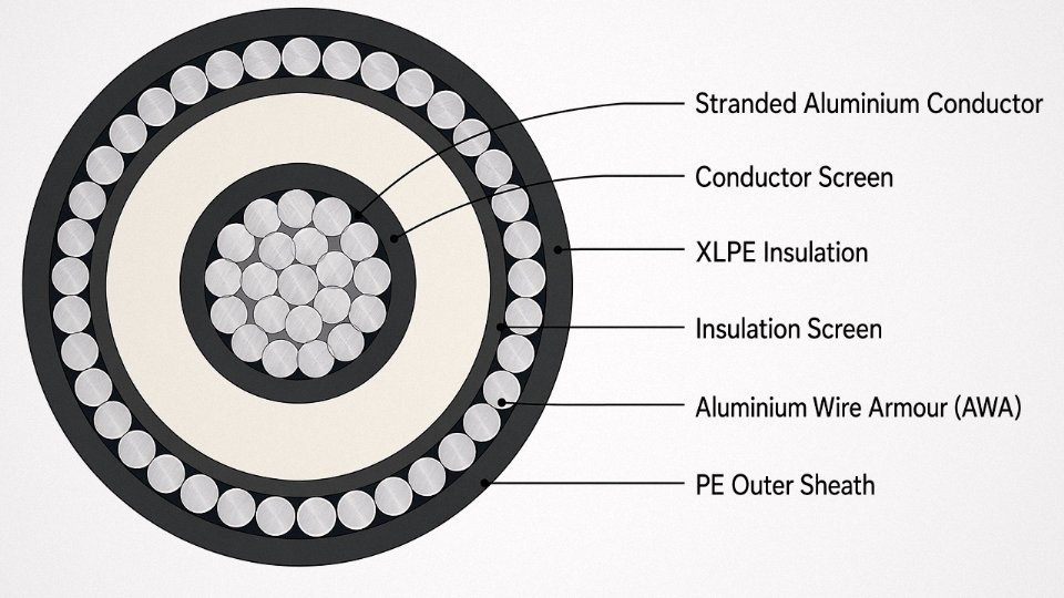
Aluminium’s natural oxide layer gives it decent passive corrosion resistance across a fairly wide range of environments. In moderately acidic or neutral soils it performs well, and in many industrial atmospheres where SWA would need additional protection, AWA or ATA with a polyethylene outer sheath handles the environment without issue.
The exception is alkaline soil, particularly where pH exceeds around 9. Aluminium’s oxide layer breaks down in strongly alkaline conditions, and corrosion can progress quietly under a sheath without obvious external signs until mechanical integrity is compromised. Direct-buried AWA cables in areas with high-pH soils — certain calcareous or contaminated industrial sites — should carry an extruded PE outer sheath as a minimum, and in genuinely aggressive conditions, it’s worth reconsidering whether aluminium armour is appropriate at all without detailed soil analysis. This catches people out more often than it should, partly because PE-sheathed AWA looks identical externally to an unsheathed cable once it’s in a trench.
Voltage Class and Typical Applications
AWA and ATA dominate single-core XLPE cable specifications in the 6–35 kV range — utility distribution feeders, large transformer tails, wind farm collector cables, data centre HV supplies. XLPE insulation operating at up to 90°C continuous conductor temperature pairs well with aluminium armour because the thermal design of the cable system already assumes careful thermal management; adding a ferromagnetic armour that generates its own heat defeats that engineering from the outset.
The practical decision rule is short: if the cable is single-core, AC, and rated above 1 kV, specify aluminium armour. The only credible exception is where individual cores face specific point-load crush risks in an unusually hazardous mechanical environment — in that case steel tape on each core might be considered, but it requires careful de-rating calculations and is unusual in standard utility or commercial building practice.
Insulation and Sheath Pairing: How XLPE, EPR, and PVC Cores Change Your Armour Compatibility
Getting the armour type right and then specifying an incompatible insulation system is a more common mistake than most procurement managers want to admit. The cable arrives on site, passes a visual check, gets installed — and three years later you’re chasing intermittent faults caused by insulation degradation that had nothing to do with mechanical damage. Material compatibility between the insulation, bedding, armour metal, and outer sheath is its own engineering decision, not an afterthought.
The Three Insulation Systems and What Their Temperature Limits Actually Mean in Practice
PVC insulation is the workhorse: cheap, widely available, and perfectly adequate for most LV distribution runs in temperate climates. Its continuous rating tops out at 70°C conductor temperature. That number matters more than people think — in a tightly packed cable tray in a warm plant room, with several cables running near full load simultaneously, you can hit that ceiling faster than any nameplate current suggests. Push past it repeatedly and the PVC plasticiser migrates, the compound hardens, and you lose the mechanical flexibility that protects the insulation at every termination bend.
XLPE handles continuous conductor temperatures up to 90°C and — critically — a short-circuit temperature ceiling of 250°C per IEC 60502. That short-circuit tolerance is why it dominates medium-voltage distribution and any circuit where fault clearance times can’t be guaranteed to be fast. The cross-linked molecular structure doesn’t flow under heat the way thermoplastic PVC does, which also means XLPE cables hold their geometry better inside armour during installation pulling.
EPR (ethylene propylene rubber) shares the 90°C continuous rating but its real advantage is flexibility at low temperatures, typically down to around -40°C. For installations in cold-store facilities, outdoor arctic-climate substations, or offshore platforms where cables must remain manageable in winter, EPR is often the only sensible choice. It’s also notably more resistant to water treeing than XLPE, which matters for submarine or persistently wet direct-burial routes.
Bedding and Inner Sheath: The Layer Most Specifiers Underestimate
Between the laid-up core assembly and the armour sits the bedding — usually an extruded layer of PVC or, in better constructions, a purpose-compounded material. This layer does three jobs: it smooths the surface for the armour wires to sit cleanly, it provides a chemical barrier between the insulation system and the armour metal, and it takes up the small relative movements between cores and armour under load cycling.
The interaction between PVC bedding and aluminium wire armour is where things get quietly problematic. Certain PVC plasticisers — particularly older phthalate-based compounds — migrate toward aluminium oxide surfaces over time, causing the bedding to stiffen and the aluminium wires to develop surface attack in humid conditions. Specifying a low-migration, aluminium-compatible PVC compound for the bedding isn’t an exotic request, but you do need to raise it explicitly with your cable manufacturer rather than assume a standard compound has been used.
Outer Sheath Selection: Environment Drives the Decision More Than Anything Else
| Insulation | Armour Type | Recommended Outer Sheath | Max. Continuous Temp. | Primary Application |
|---|---|---|---|---|
| PVC | SWA or STA | PVC ST2 | 70°C | General industrial, LV distribution |
| XLPE | SWA or AWA | PVC ST2 or LSZH | 90°C | MV feeders, power stations, commercial buildings |
| XLPE | AWA | HDPE | 90°C | Direct burial, aggressive soil conditions |
| EPR | AWA or SWA | LSZH or Polyurethane | 90°C | Offshore, cold climates, public transport tunnels |
| PVC | ATA | LSZH | 70°C | Single-core tray runs, tunnel lighting circuits |
PVC ST1/ST2 sheaths cover the majority of industrial installations without drama. LSZH becomes non-negotiable once you’re inside a tunnel, a densely occupied public building, or any space where evacuation in a cable fire is a genuine life-safety scenario — the toxicity and visibility issue in a burning PVC sheath is real, not regulatory theatre. HDPE outer sheaths offer substantially better resistance to soil-stress cracking and ground moisture than PVC, which is why direct-burial specifications in waterlogged or chemically active soils increasingly call for it even at modest cost premium. Polyurethane is heavier and more expensive but handles abrasion on factory floors — trailing cables on automated guided vehicle routes, for instance — in a way that standard PVC simply doesn’t.
XLPE-insulated armoured cables can sustain short-circuit conductor temperatures up to 250°C per IEC 60502True
IEC 60502 specifies 250°C as the maximum conductor temperature during a short-circuit event for XLPE-insulated cables, which is significantly higher than the 160°C limit for PVC-insulated equivalents, making XLPE the appropriate choice where fault protection coordination may result in longer clearance times.
Where Custom Compounding Changes the Calculation
Standard catalogue constructions cover perhaps 80% of projects. The remaining 20% — cables running through petrochemical splash zones, installations requiring specific fire test classifications beyond standard EN 50575, UV-stabilised outer sheaths for exposed rooftop runs in high-UV climates — typically require the manufacturer to adjust sheath formulations. Jinda’s in-house compounding operation means those adjustments happen at the raw material stage rather than through a third-party compounder, which in practice eliminates one approval round and keeps lead times from blowing out. For a project specifying, say, a mud-resistant HDPE outer sheath with a defined hardness range for cable protection in a directional-drilled installation, that compounding flexibility is the difference between a cable that performs and one that technically meets the standard but fails in service within a season.
Installation Environment Decoder: Underground, Tray, Aerial, Subsea, and Hazardous-Area Routes
The armour type you select means nothing if it’s mismatched to the physical conditions of the route. A cable that survives a tensile test in the lab can fail within two years when buried in waterlogged clay, run across a tray at 45°C ambient, or terminated with the wrong gland in a Zone 1 atmosphere. Each environment below has its own set of failure modes, and the specification has to address all of them — not just the obvious one.
Direct Burial in Standard Soil
SWA with an HDPE outer sheath is the workhorse here. HDPE resists soil moisture, chemical attack from ground salts, and the mechanical abrasion that PVC sheaths quietly accumulate over years of seasonal ground movement. Bury LV cables at a minimum of 0.6 m and MV cables at 0.9 m per IEC 60364 guidance — though in practice, many contractors go to 1.0–1.2 m in agricultural land where deep ploughing is routine.
Route markers every 10–15 m and concrete protection tiles above the cable are not optional niceties in trafficked zones; they are the difference between a cable that lasts 30 years and one that gets excavated by a mini-digger in year four. Tile colour coding (yellow for gas, red for LV power, black for MV in most European conventions) matters too — it is one of those small details that procurement sometimes strips out to save a few cents per metre and then regrets during civil works.
SWA cables compliant with IEC 60502-2 are rated for burial depths of 0.5–1.2 m in standard soil, depending on voltage grade and soil classification.True
IEC 60502-2 and BS 5467 specify mechanical performance requirements for armoured cables in direct burial; burial depth guidance of 0.6 m for LV and 0.9 m for MV aligns with IEC 60364-5-52 installation practice, with deeper installation required in disturbed or trafficked ground.
Cable Tray and Ladder Rack
On tray, STA suits multi-core cables where point loads from tray rungs matter more than longitudinal tension. For single-core cables — especially in larger conductor sizes — AWA is the correct choice because steel wire armour on a single-core AC circuit creates a closed magnetic loop that generates eddy current losses and measurable heating under full load.
Weight adds up fast on long horizontal runs. AWA typically reduces cable mass by roughly 30–40% compared to an equivalent SWA construction, depending on conductor cross-section and armour wire diameter. On a 50-metre tray span carrying 20 cables, that difference in load can determine whether you need intermediate supports. Tray fill ratios and cable derating per IEC 60287 must both be checked — bundling correction factors can push operating temperature above sheath rating if the engineer only checks the conductor ampacity and forgets the thermal environment of the bundle.
Aerial Installation and Overhead Runs
Self-supporting constructions — either AWA with a separate catenary or purpose-built aerial bundled cable with integrated messenger — need wind and ice loading calculations specific to the site’s climatic zone. IEC 60826 provides the framework; the inputs (wind pressure, ice sleeve thickness, span length) come from local meteorological data and should not be assumed from a project in a different region.
Sag limits matter for both clearance and mechanical fatigue. Sag that looks acceptable at 20°C installation can become a clearance violation at peak summer conductor temperature. UV-stabilised outer sheaths are non-negotiable — standard black HDPE with carbon black provides adequate UV resistance in most climates, but check the sheath specification explicitly if the route runs at altitude or in high UV-index geographies.
Subsea and Waterlogged Ducts
There is an important distinction that often gets collapsed in specifications: a submarine power cable designed for seabed laying is not the same product as an armoured land cable installed in a flooded duct. For shallow marine crossings, river crossings, and tidal zone installations, Double Steel Wire Armour (DSWA) provides the tensile strength to resist hydrodynamic drag and mechanical damage from boat anchors or shifting substrate. The two armour layers — counter-helically applied — also resist torsional stress during cable laying.
For flooded or submerged duct runs on land, longitudinal water-tight construction per IEC 60502-4 — water-blocking tape, swellable powder filling, or a combination — prevents water migration along the cable core after any sheath breach. Water that tracks 80 metres inside a cable before the fault is located has caused more extended outages than the original damage event. Specifying a water-blocked construction adds cost, but it is cheap insurance on any route where the duct could flood.
Hazardous Areas: Zone 1, Zone 2, and Division Classifications
SWA with correctly rated cable glands is the established solution for ATEX (IEC 60079-14) and IECEx-compliant installations in Zone 1 and Zone 2 atmospheres. The armour does double duty here: it provides mechanical protection and, critically, forms the equipotential bonding path required to prevent incendive sparking at termination points. Armour continuity must be verified at both ends — a loose or corroded gland defeats the bonding function entirely, and that is the kind of thing that passes visual inspection but fails under a continuity meter.
For Division 1 and Division 2 classifications under NEC Article 501, the same SWA principle applies, but gland selection must match both the cable construction and the enclosure’s explosion-proof or intrinsically safe rating. Mismatched glands — for instance, using a gland rated for a smaller armour wire diameter — are common on sites where procurement sources glands separately from cable, and the fit is checked by hand rather than by specification.
One operational point worth stating plainly: the armour on an SWA cable in a hazardous area is not optional shielding. It is a functional safety component. Treat it accordingly in maintenance procedures and in the procurement specification.
Voltage Class and Core Configuration: Selecting Armoured Cable for LV, MV, and HV Systems
Getting the voltage class right before you specify anything else is non-negotiable. An under-insulated cable in an MV ring main will fail — sometimes catastrophically — within months. Over-specified insulation on a simple LV sub-main won’t cause a fault, but it will quietly inflate your material cost by 20–50% on a large project, and that’s real money left on the table.
Low Voltage Systems (Up to 1 kV)
For the bulk of industrial and commercial distribution work — sub-mains from switchboards, feeds to motor control centres, distribution to lighting panels — LV armoured cable is the workhorse. PVC-insulated SWA to BS 5467 or XLPE-insulated SWA to IEC 60502-1 covers the vast majority of applications. XLPE is the better choice wherever conductor temperatures will push above roughly 70°C or the route involves sustained high loading; PVC is adequate for lighter-duty intermittent feeds and keeps first cost down.
Core count follows load type. Single-phase circuits take 2-core; three-phase without neutral takes 3-core; three-phase with neutral (the most common industrial arrangement) takes 4-core; add a fifth core if you need a dedicated earth separate from the armour — which you often do in TN-S systems or where the armour continuity cannot be guaranteed across joints. Conductor sizes in LV armoured cable typically run from 1.5 mm² through 400 mm², though above roughly 150–185 mm² you’re usually better served moving to single-core cables laid in trefoil rather than wrestling with an increasingly stiff and heavy multi-core.
Medium Voltage Systems (1 kV to 35 kV)
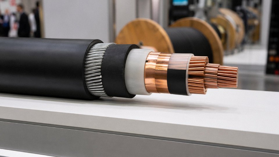
MV specification is where most procurement errors actually happen, in my experience, because the insulation system becomes genuinely complex. At these voltages, stress control at the conductor screen and insulation screen interfaces is as important as the bulk dielectric thickness. XLPE is the standard choice for utility feeders, wind farm collection circuits (typically 11 kV to 33 kV), and campus distribution rings. EPR remains the preferred insulation for submarine sections, flexible industrial connections, or anywhere that water-tree resistance needs to be maximised — EPR is inherently less susceptible.
Individual screened cores (each core with its own metallic screen) are required above about 3.8 kV line-to-earth in most utility specifications; below that, an overall screen on a multi-core cable is sometimes acceptable, but check your network operator’s standard before assuming. For multi-core MV cables, SWA is the conventional armour. For single-core MV cables — say, a 33 kV feeder where you’re pulling three individual cables — you must use AWA or ATA to avoid the induced circulating currents and associated losses that steel armour would cause on a single-core AC cable. This isn’t a minor efficiency quibble; on a heavily loaded 33 kV single-core with SWA, the armour heating losses can approach 10–15% of conductor losses, which compounds over the cable’s 30-year service life.
Steel wire armour on single-core AC cables at MV creates significant eddy current and hysteresis losses that do not occur with aluminium wire armour.True
Steel is ferromagnetic; the alternating magnetic field from a single-core AC conductor induces circulating currents and magnetic hysteresis in a steel armour layer, generating heat and reducing effective current-carrying capacity. Aluminium is non-magnetic, so AWA on single-core AC cables avoids this effect entirely. This is well-established in IEC 60287 loss factor calculations.
Governing standards for this class are IEC 60502-2 and BS 6622, with conductor sizes ranging from 16 mm² up to 630 mm² in most standard production runs, though 800 mm² and 1000 mm² are available for high-capacity feeders.
High Voltage Systems (Above 35 kV)
Above 35 kV, the cable construction shifts substantially. Extruded solid-dielectric cables — still XLPE for the insulation — move away from conventional wire or tape armour and instead use a corrugated aluminium metallic sheath or, in older and some specialist designs, a lead sheath. That metallic sheath performs multiple roles simultaneously: it provides the earth return path, acts as a radial moisture barrier, and delivers the mechanical protection that armour provides at lower voltages. The governing standard is IEC 62067 for cables above 150 kV; IEC 60840 covers the 30–150 kV range. Jinda’s HV production base handles this segment, extending the group’s capability well beyond the commodity LV and MV cable supply that dominates most manufacturers’ output.
Single-Core Trefoil vs. Multi-Core: The Real Trade-off
For three-phase systems in the 95–300 mm² range, the choice between a single multi-core cable and three single-core cables in trefoil formation comes up constantly. Multi-core is cheaper to install — one pull, one set of terminations, and the mutual heating effects between phases are already accounted for in the multi-core current-rating tables. Three single-cores in trefoil cost more in labour and conduit space, but they’re easier to handle on long runs (each drum is lighter), and they’re the only practical option once you’re above roughly 185–240 mm² conductor because a 4-core 240 mm² SWA cable gets heavy enough that pulling and bending on site becomes a genuine site-safety issue, not just an inconvenience.
Flat formation for single-cores increases the spacing between outer phases and the centre phase, which means the centre cable runs hotter — derate accordingly, usually by 5–8% depending on soil thermal resistivity and burial depth, or check IEC 60287 directly rather than guessing.
Quick-Reference Specification Table
| Voltage Class | Insulation | Screen Type | Armour Type | Key Standard | Typical Conductor Range |
|---|---|---|---|---|---|
| LV (≤1 kV), multi-core | PVC or XLPE | None | SWA or STA | IEC 60502-1 / BS 5467 | 1.5–400 mm² |
| MV (1–35 kV), multi-core | XLPE or EPR | Individual core screens | SWA | IEC 60502-2 / BS 6622 | 16–630 mm² |
| MV (1–35 kV), single-core | XLPE or EPR | Single metallic screen | AWA or ATA | IEC 60502-2 / BS 6622 | 35–1000 mm² |
| HV (35–150 kV), single-core | XLPE | Metallic sheath integral | Corrugated Al or lead sheath | IEC 60840 | 95–2500 mm² |
| EHV (>150 kV), single-core | XLPE | Metallic sheath integral | Corrugated Al or lead sheath | IEC 62067 | 400–2500 mm² |
Conductor size ranges are typical production band values; the actual upper limit depends on the manufacturer’s equipment and tooling, and the lower limit for MV is set by minimum insulation thickness requirements rather than current-carrying capacity.
International Standards and Approvals: Matching Your Armoured Cable to IEC, BS, AS/NZS, and Regional Requirements
Getting the armour type right mechanically is only half the job. The other half — and the one that bites procurement teams hardest — is confirming that the cable you’ve ordered actually carries the compliance documentation the destination market will accept. Customs holds, commissioning delays, and forced re-procurement are almost always avoidable. They happen when someone assumes a CE mark covers a UK project post-2021, or when an Australian contractor discovers the submitted test reports reference IEC 60502 but the specification required AS/NZS 5000.1 type-testing.
The Core Standards Families and What They Actually Govern
IEC 60502 (Parts 1 and 2, covering LV and MV respectively) is the global baseline for extruded-insulation power cables. Most international project specifications will accept IEC 60502-2 compliance as sufficient, particularly in the Middle East, Southeast Asia, and across much of Africa. That said, “IEC-compliant” is not a single, monolithic claim — the standard defines construction requirements, conductor dimensions, insulation and sheath thicknesses, armour wire sizes, and a battery of electrical and mechanical type tests. A manufacturer needs to have actually run those type tests on a statistically representative sample, not just built to the dimensional tables.
BS 5467 (PVC-insulated) and BS 6724 (LSZH-sheathed) remain the reference standards for UK infrastructure projects and for Commonwealth markets — parts of the Gulf, East Africa, Hong Kong, and older-generation Australian projects in particular — where British engineering influence persists in client specifications. These standards differ from IEC 60502 in some sheath thickness tolerances and test methods, subtly enough that a cable built purely to IEC dimensions can fail a BS 5467 type-test comparison.
AS/NZS 5000.1 covers power cables for Australia and New Zealand and includes its own construction requirements, including specific armour wire tensile and resistance values. It’s worth noting that Australian projects will typically require SAA or NATA-accredited test reports, not just an IEC certificate — a detail that catches overseas suppliers off guard regularly.
Third-Party Certification Bodies
The certification body matters as much as the standard. For UK projects: BASEC approval is effectively expected on any BS 5467 or BS 6724 cable; a BASEC mark signals ongoing factory audits, not just a one-time type test. Intertek and SGS are broadly accepted across Middle Eastern, African, and Asian export markets, and both run accredited cable testing labs. TÜV (Rheinland or SÜD) carries strong weight in European industrial and infrastructure tenders. For offshore, subsea, or marine installations, DNV type approval is the one to ask for — an offshore platform project manager simply won’t move forward without it.
Jinda holds type-test certificates from accredited third-party labs and can provide project-specific documentation packages including BASEC, Intertek, and SGS reports.True
This is consistent with Jinda's stated international export operations across 50+ countries and their integrated R&D and QA infrastructure; customers should request the specific certificate numbers and scopes during procurement confirmation.
CE marking covers EU market access. Post-Brexit, UK projects require UKCA marking — the two are not interchangeable, and this has caused real problems on split UK/EU projects.
Product Standard vs. Installation Code — A Critical Distinction
This one is genuinely misunderstood. A product standard like IEC 60502-2 defines how the cable is built and what tests it must pass. An installation code — IEC 60364, BS 7671, the NEC in North America — defines how that cable is used once it’s on-site. A cable can be fully IEC 60502-2 compliant and still need to be buried at 750 mm rather than 500 mm under the local code, or terminated with specific gland types, or derated based on grouping factors the product standard doesn’t touch.
Armour earthing is where this distinction has the biggest practical consequence. BS 7671 (the UK Wiring Regulations) permits and in some configurations requires SWA armour to function as the circuit protective conductor, which means the armour cross-sectional area needs to be verified against earth fault current requirements, not just selected for mechanical protection. IEC 60364 treats armour as a supplementary protective measure rather than a primary protective conductor in most configurations. Specifying the wrong arrangement means either an under-sized armour for fault-current duty or an unnecessarily heavy cable that adds cost across the whole route length.
Jinda’s Documentation Package for Export Projects
In practice, a complete compliance package for an international armoured cable order should include: third-party type-test reports referencing the applicable standard and construction, material certificates for conductor, insulation, armour, and sheath compounds, factory acceptance test (FAT) records tied to the specific production run, drum-by-drum packing lists with exact lengths and drum numbers, and CE or UKCA declarations of conformity where the destination market requires them. Jinda provides all of these as standard for export shipments — not as an upsell. Getting this documentation right at order stage, rather than scrambling for it at port or during commissioning, is usually worth the conversation before the purchase order is raised.
Conductor Material and Cross-Section Sizing: Copper vs. Aluminium Conductors Inside Armoured Cables
The armour type gets most of the attention in cable specifications, which is understandable. But conductor material is just as consequential, and it interacts with armour selection in ways that aren’t always obvious until you’re staring at a cable schedule that doesn’t quite fit the conduit route you planned.
Conductivity, Cross-Section, and What the Numbers Actually Mean
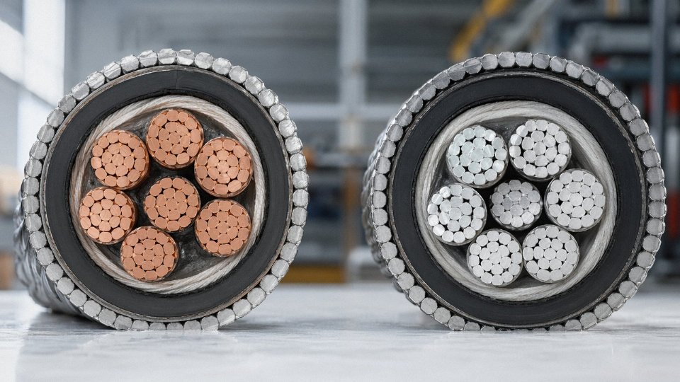
Copper conducts at roughly 58 MS/m; aluminium sits around 35 MS/m. That gap means an aluminium conductor needs a larger cross-section to carry the same current — and “larger” compounds through the whole cable construction. A 150 mm² copper conductor SWA cable and a 240 mm² aluminium conductor SWA cable are broadly equivalent under IEC 60287 reference conditions (ground temperature 20°C, standard burial depth, typical thermal resistivity). But the 240 mm² aluminium cable has a noticeably bigger overall diameter, which can push the armour wire diameter into the next standard size per IEC 60502-2, increasing total cable weight and tightening what you can practically do with minimum bending radius on site.
The equivalency ladder below is a practical conversion tool for specifiers switching between copper and aluminium specifications mid-project:
| Copper Conductor (mm²) | Approximate Aluminium Equivalent (mm²) |
|---|---|
| 16 | 25 |
| 25 | 35–50 |
| 35 | 50–70 |
| 50 | 70–95 |
| 70 | 95–120 |
| 95 | 150 |
| 120 | 185 |
| 150 | 240 |
| 185 | 300 |
| 240 | 400 |
| 300 | 500 |
| 400 | 630 |
These are working approximations — actual equivalency depends on installation method, grouping, ambient temperature, and whether you’re using a correction factor for soil thermal resistivity. Don’t treat the table as a substitute for a proper IEC 60287 calculation on critical circuits.
How Conductor Choice Feeds Back Into Armour Selection
This is the bit that catches people out. If a project starts with a copper-based cable schedule and then procurement switches to aluminium to cut material cost — which is legitimate, aluminium conductors typically run 50–60% cheaper by weight and around 70% lighter per unit length — the overall cable diameter increases enough that the armour wire sizing steps up. On long runs, that adds back weight you thought you’d eliminated. On cable tray installations with weight limits, it can matter. The revised bending radius also needs checking against any duct bends or tray corners already fixed in the design.
In my experience, this substitution happens most often on utility LV distribution mains, where the cost saving is real and the installation team has the space to handle larger drums and stiffer cable. For industrial control wiring, instrumentation loops, and MV circuits in space-constrained switchrooms or cable cellars, copper remains the standard choice — not because of sentiment, but because the smaller diameter genuinely matters when you’re threading through full cable trays or terminating inside compact switchgear.
Termination and Jointing: The Part That Gets Specified Too Late
Aluminium conductors require proper bi-metallic connectors or tinned copper compression lugs at every interface with copper busbars or equipment terminals. Galvanic corrosion at aluminium-to-copper joints is not a slow, gradual problem — in humid or coastal environments it can degrade a termination within a few years if unprotected. Anti-oxidant compound must be applied during crimping; aluminium re-oxidises within minutes of the surface being cleaned.
Aluminium conductor cables require bi-metallic connectors and anti-oxidant compound at copper interfaces to prevent galvanic corrosion.True
Aluminium and copper form a galvanic couple (approximately 0.5–1.0 V potential difference depending on electrolyte conditions); without bi-metallic hardware and anti-oxidant compound, the aluminium oxidises and joint resistance increases, causing localised heating and eventual failure. This is consistent with IEC 61238-1 jointing requirements and standard industry practice.
These requirements should be written into the cable installation specification, not left to the contractor’s discretion. Specifying the cable correctly and then leaving termination method unaddressed is a common gap — the cable performs fine, the joint fails, and the fault investigation takes weeks.
Where Each Material Wins in Practice
Copper conductors dominate in industrial control, instrumentation, and space-constrained MV installations. The smaller cross-section, better flexibility (particularly relevant in multicore SWA cables where flexing during installation is unavoidable), and straightforward termination justify the material premium. Aluminium conductors make strong economic sense on long-run LV distribution mains, utility-scale MV feeders, and any route where drum weight and total installed cable weight are real constraints. The lifecycle material cost difference is significant enough that on a feeder run of several kilometres, the saving on conductor material alone can offset the extra jointing hardware cost many times over.
The decision isn’t ideological. It’s a calculation — diameter, weight, termination complexity, and total installed cost against the copper premium for that specific circuit.
Frequently Asked Questions About Armoured Cable Selection
These questions come up repeatedly — in specification meetings, during procurement review, and sometimes at the worst possible moment, which is on-site during termination. The answers below are direct.
Can I use SWA cable outdoors without a conduit?
Yes, but the outer sheath matters more than most people give it credit for. Standard black PVC (ST2 grade) or black HDPE sheaths both carry UV stabiliser packages adequate for outdoor exposure — unpigmented or grey sheaths generally do not, and you will see surface crazing within two to three years in high-UV climates. Beyond sheath chemistry, support spacing needs to follow the manufacturer’s installation guide; for typical 4-core LV SWA in the 16–95 mm² range this is usually 350–550 mm on horizontal runs, somewhat less on vertical ones. Termination glands must be rated IP66 minimum — IP68 if water pooling is plausible at any entry point. Skimping on gland rating is one of those decisions that looks fine at commissioning and then causes a warranty dispute eighteen months later.
What is the difference between armoured cable and screened cable?
They solve completely different problems and the terms get conflated constantly. Armour — steel wire, steel tape, aluminium wire — is purely mechanical protection against crush, impact, and rodent damage. A screen (copper foil, copper braid, or drain wire) is there to manage electromagnetic interference, either shielding sensitive signal cores from external noise or preventing a power cable from radiating into adjacent instrumentation. The confusion arises because you can have both in one cable: individually screened cores inside an overall SWA construction is entirely standard for instrumentation trunking that also needs burial protection. Two different layers, two different functions.
Is the armour of an SWA cable a suitable protective earth conductor?
Under BS 7671 the short answer is yes, conditionally. The armour can act as a circuit protective conductor provided its cross-sectional area satisfies the adiabatic equation S = √(I²t)/k — and on smaller cable sizes it often does not, which means you need a separate earth core or an oversized armour. Under IEC 60364 the convention leans toward a dedicated earth core regardless, and many project specifications in the Middle East, Southeast Asia, and sub-Saharan Africa simply mandate it to avoid the calculation argument on-site. Always confirm with the local authority having jurisdiction before terminating armour as the sole CPC.
Under BS 7671, SWA armour can serve as a circuit protective conductor if its cross-sectional area meets the adiabatic equation requirements.True
BS 7671 Regulation 543.2 permits metallic armour as a protective conductor subject to the cross-sectional area check via the adiabatic equation; it is not unconditional and smaller cable sizes frequently fail the check.
How do I specify armoured cable for a direct-burial solar farm project?
The core specification line should read: XLPE-insulated, copper or aluminium conductor, SWA or DSTA (Double Steel Tape Armour) where additional crush resistance is needed on rocky ground, rated 1 kV DC or AC as appropriate to the string or feeder circuit, black HDPE outer sheath for UV and soil-chemical resistance. Flame retardancy to IEC 60332-1 is the usual minimum; some EPC contractors call for IEC 60332-3 Category C at the inverter building entry. Confirm the DC voltage rating explicitly — a cable marked 0.6/1 kV AC is not automatically approved for 1 kV DC, and some manufacturers rate them differently.
What minimum order quantity does Jinda require for armoured cable?
For standard LV SWA products held in production stock, one full drum — typically 500 m or 1,000 m depending on cable cross-section — is the practical minimum. Custom constructions, meaning non-standard sheath colours, special conductor alloys, or voltage ratings outside the standard range, require a conversation at the enquiry stage to agree quantities that make the production run viable. In practice most project enquiries above roughly 5–10 km of a given type are straightforward; smaller trial quantities for a specific non-standard build are negotiable and worth asking about directly rather than assuming a hard cutoff.
How long does Jinda take to manufacture and ship a bulk armoured cable order?
Standard LV SWA cables can typically be dispatched within 15–25 working days for volumes up to around 50 km, assuming no unusual raw material constraints — copper rod pricing and availability has been volatile enough in recent years that it is worth confirming lead times at the time of order rather than relying on a number from a catalogue. MV XLPE armoured cables requiring specific type tests run 30–45 working days as a realistic range. HV cables, or any construction requiring third-party witness testing, are quoted individually because the bottleneck is usually the test laboratory schedule rather than manufacturing capacity.
What does LSZH armour bedding add to the cable cost, and why would I specify it?
Roughly 10–20% premium over standard PVC construction, depending on cable size and sheath wall thickness — the percentage is higher on smaller cables where sheath material cost is a bigger fraction of total build cost. The reason to specify it is not optional in many project categories: tunnels, metro systems, airports, and most public buildings in jurisdictions following IEC 60332-3 and IEC 61034-2 require it because conventional PVC releases hydrogen chloride and dense black smoke when it burns, both of which kill people trying to evacuate. The cost argument against LSZH rarely survives a conversation with the project’s fire safety engineer.
How to Write a Complete Armoured Cable Procurement Specification and Work With Jinda’s Technical Team
A vague cable enquiry — “we need 3-core 95mm² armoured cable, roughly 2km” — will get you a quotation, but probably not the right one. Experienced procurement managers know that a single missing parameter, say a forgotten screen requirement or an unspecified sheath compound, can mean the delivered cable is technically non-compliant or simply wrong for the site conditions. Getting the specification tight before you send the enquiry saves weeks.
The Specification Checklist That Prevents Costly Rework
Work through these parameters in order. Every one of them affects either the design, the price, or the lead time — usually all three.
Voltage rating: State U₀/U in kV explicitly. 0.6/1 kV, 3.6/6 kV, 6/10 kV, 8.7/15 kV, 12/20 kV, 18/30 kV — these are not interchangeable. A cable ordered at the wrong voltage class will fail type testing and cannot be commissioned.
Core configuration: Number of power cores and cross-section in mm², plus whether you need a separate reduced neutral (common in European LV distribution) or a full-size neutral. Then pilot or earth cores — cross-section, insulation colour, and whether they’re integrated in the same cable or a separate run. Overlooking the pilot cores on a motor feeder is a surprisingly common procurement error.
Conductor material: Copper or aluminium. If aluminium, confirm the jointing materials and termination hardware specified for site — aluminium conductors in the 95–300 mm² range are perfectly serviceable, but using copper-only lugs causes long-term creep failures at terminations.
Insulation type and temperature class: XLPE (90°C continuous), EPR, or PVC (70°C). For MV and HV, XLPE is effectively standard now. State whether you need individual conductor screens.
Screen type: Copper tape screen, copper wire screen, or none. Critical for single-core MV/HV cables and for installations near sensitive instrumentation.
Armour type and material: SWA, STA, AWA, or ATA — and state the reason if non-standard, because it helps the technical team sanity-check the choice against your installation environment.
Inner bedding and outer sheath compound: Standard PVC, LSF (low smoke and fume), LSZH, or HDPE for direct burial. Specifying the wrong sheath on a tunnel installation is a real fire-safety risk, not a paperwork issue.
Colour coding standard: IEC, BS 7671, AS/NZS, or project-specific. This matters for customs inspection in some markets and always matters for installation contractors.
Drum length and reel type: Specify preferred drum lengths (e.g., 500 m, 1000 m, or project-optimised cuts to minimise joints). State whether wooden drums or steel reels are required — some offshore and aerial projects prohibit wooden drums due to pest-risk import regulations.
Applicable standard and test certificates: IEC 60502-1/-2, BS 5467, AS/NZS 1429, or a project-specific addendum. Request a drum-by-drum test certificate as a default; factory acceptance test (FAT) with witness if the project warrants it.
How the Jinda Enquiry Process Actually Works
Submit your cable schedule, single-line diagram, or even a partially complete specification to Jinda’s international sales team. Within roughly 24 hours, a technical engineer — not a junior sales rep — will contact you to close any gaps or flag incompatibilities. The formal quotation typically follows within 48–72 hours and includes unit weight per metre, drum schedule with outer dimensions, and gross shipping weight. That last part matters more than people realise: a 1,000 m drum of 3-core 240 mm² SWA cable can weigh over 4 tonnes, and finding that out at the freight-booking stage rather than at the quotation stage causes real schedule pain.
Jinda's international quotations include drum schedule, unit weight, and shipping dimensions as standard.True
This is stated as part of Jinda's documented quotation process and is consistent with professional cable manufacturer practice for export projects.
What Separates a Manufacturer From a Trading Company
Jinda offers factory acceptance testing with either customer or independent third-party witness — useful on large infrastructure contracts where the project owner requires evidence beyond a routine test certificate. For sizeable project shipments, GPS drum tracking is available, which is genuinely useful when a critical cable package is transiting through multiple ports and your installation crew is waiting on it.
All technical documentation — test reports, routing sheets, drum labels — is issued in English as standard for export orders. That matters at customs and matters again when the installation contractor needs to verify the cable construction against the project specification on a tight schedule.
Parallel Manufacturing Across Five Production Bases
One practical advantage of Jinda’s five production bases is the ability to run different cable types simultaneously against a single project delivery window. LV SWA feeders for a substation civils package can run at one facility while MV XLPE armoured cable for the same project’s distribution network runs at a second. For large EPC projects where a cable package spans several voltage classes and construction types, that parallel capacity can shave three to six weeks off the overall schedule — the kind of thing that rarely features in a brochure but matters enormously when a commissioning date is fixed.
Submit Your Specification
If you have a cable schedule, a project single-line diagram, or simply the checklist above filled in as far as it goes, send it to Jinda’s international sales team. With 35+ years of export experience, customers across more than 50 countries, and the manufacturing depth to handle both small top-up orders and full project cable packages, Jinda’s technical team can turn a specification into a confirmed, compliant supply plan faster than most trading intermediaries can even source a price.