Poor cable selection is one of those mistakes that doesn’t announce itself immediately. You get a system that tests fine on day one, then six months later you’re chasing intermittent dropouts, fielding complaints about pixelated channels, or watching signal levels degrade floor by floor in a multi-dwelling unit until half the building can’t hold a stable DOCSIS connection. The underlying cause — wrong cable type, undersized conductor, cheap foil coverage — was baked in long before the first subscriber ever plugged in a set-top box. Replacing cable inside finished walls or buried conduit costs orders of magnitude more than getting the spec right at procurement.
For cable TV distribution, RG-6 quad-shield coaxial cable with a solid copper-clad steel center conductor and 75-ohm impedance is the standard choice for most residential and commercial installations. It delivers attenuation of roughly 1.5–2.5 dB per 100 feet at 1 GHz — meaningfully better than RG-59 — and handles the full 5 MHz to 1,002 MHz DOCSIS 3.1 frequency range without the signal loss that forces expensive amplifier cascades.
What makes this more complicated in practice is that “RG-6” covers a surprisingly wide range of actual product quality, and two cables wearing the same label can perform very differently once you’re dealing with long runs, outdoor exposure, or high-split HFC architectures pushing toward 1.2 GHz. The conductor material, shielding construction, and dielectric consistency all matter — sometimes more than the cable designation itself.
How Cable TV Signal Transmission Works and What It Demands from a Wire
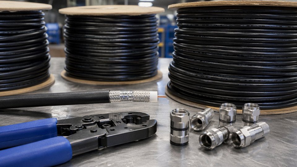
Most people picture cable TV as a simple wire running from a wall plate to the back of a set-top box. The actual infrastructure behind that connection is considerably more demanding — and the physical wire in that last stretch is where a surprising amount can go wrong.
The HFC Architecture: Fiber Gets You Close, Coax Gets You There
Cable operators today almost universally use a Hybrid Fiber-Coaxial (HFC) network. Fiber optic trunk lines carry the signal from the headend to a neighborhood node — typically serving anywhere from a few dozen to a few hundred homes depending on how aggressively the operator has segmented the network. From that node, coaxial cable takes over for the “last mile,” distributing signal through a tap-and-splitter cascade to individual homes, apartment buildings, and MDUs.
That coaxial segment is where wire selection actually matters. The fiber portion is engineered, spliced, and maintained by the operator. The drop cable from the tap to your premises — and all the internal wiring in a commercial building or multi-unit property — is your problem. And it accumulates attenuation, picks up ingress noise, and reflects energy back toward the source if it isn’t specified correctly.
Why 75 Ohms Is Not Negotiable
Cable TV distribution is standardized at 75-ohm characteristic impedance. This isn’t arbitrary — it represents a practical compromise between minimum attenuation and maximum power handling for coaxial cables in the diameter ranges commonly used in distribution networks. Every component in the signal path, from the amplifier output to the splitter to the wall plate, is designed around 75 ohms.
Using 50-ohm coaxial cable in a 75-ohm cable TV distribution system causes significant signal reflection loss.True
Impedance mismatch between 50-ohm and 75-ohm systems creates standing waves at the junction. The reflection coefficient at a 50-to-75-ohm interface is approximately 0.2, which translates to a return loss of roughly 14 dB and an insertion loss of around 0.5–1.0 dB at the mismatch point — measurable and cumulative across multiple junctions.
Substitute 50-ohm cable — the kind used in RF test equipment, amateur radio, and cellular installations — and you immediately introduce standing-wave reflections at every connector and junction. Depending on frequency and how many mismatched points exist in the run, you can lose 3–6 dB just to reflections, before the cable itself has attenuated anything. For a system already operating at minimum acceptable signal level, that’s the difference between a clean picture and a pixelating or dropped signal.
The Three Parameters That Define Wire Performance
Attenuation is the most visible number on a cable datasheet: how much signal power is lost per unit length. It increases with frequency, which is why a cable that performs adequately at 100 MHz may fail at 750 MHz on the same run length. Return loss quantifies how much reflected energy bounces back from impedance discontinuities — connectors, splices, or a cable that drifts from its nominal 75-ohm spec due to physical damage or poor manufacturing tolerance. Shielding isolation, expressed in dB, measures how well the cable rejects external RF interference from ingress sources like LTE signals, switching power supplies, and in older buildings, fluorescent lighting ballasts. For DOCSIS upstream channels, which operate in the 5–42 MHz range (expanding to 5–204 MHz under DOCSIS 3.1), poor shielding isolation is often the first cause of upstream noise problems that get misdiagnosed as amplifier issues.
Frequency Demands: The Spectrum Keeps Expanding
Standard analog cable TV systems were designed around 550 MHz. Digital cable and DOCSIS 3.0 pushed the upper boundary to 750 MHz. DOCSIS 3.1 extended that to 1,002 MHz, and next-generation HFC deployments targeting DOCSIS 4.0 are now specifying cables rated to 1.2 GHz. The practical rule: always select a cable rated at least 15–20% above the highest frequency your system actually carries. A cable rated exactly to 1 GHz operated at 1 GHz is operating at its certification limit — any degradation from aging, temperature cycling, or connector oxidation pushes it past spec.
Velocity of Propagation and Phase Distortion on Long Runs
Velocity of propagation (VOP) expresses how fast the electrical signal travels through the cable’s dielectric as a percentage of the speed of light in vacuum. Foam polyethylene dielectric, common in quality RG-6 construction, typically yields a VOP in the 82–87% range. Solid polyethylene drops that to roughly 66%. On short residential drops this barely matters. On longer internal building runs — say, 150–200 feet of home-run wiring in an MDU — lower VOP introduces phase differences between frequencies, which at broadband data rates contributes to inter-symbol interference and measurable upstream MER degradation. It’s subtle enough that most technicians don’t measure it, but it shows up in DOCSIS pre-equalization coefficients if you know what to look for.
RG-59 vs. RG-6 vs. RG-11: A Specification-by-Specification Comparison
These three cable types look similar on a reel and feel similar in your hand. The differences show up at 750 MHz and above — and that’s exactly where DOCSIS 3.1 and modern HFC systems live.
The Numbers Side by Side
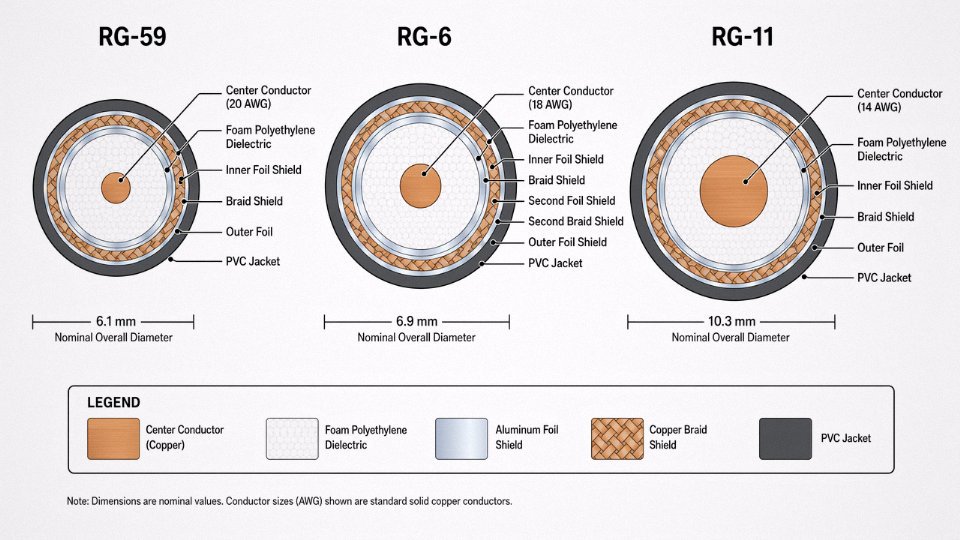
| Specification | RG-59 | RG-6 | RG-11 |
|---|---|---|---|
| Center conductor | 20 AWG (0.81 mm) | 18 AWG (1.02 mm) | 14 AWG (1.63 mm) |
| Dielectric type | Solid or foam PE | Foam polyethylene | Foam polyethylene |
| Shielding | Single or dual braid | Dual or quad (foil + braid) | Dual (foil + braid) |
| Nominal OD | ~6.1 mm | ~6.9 mm | ~10.3 mm |
| Characteristic impedance | 75 Ω | 75 Ω | 75 Ω |
| Attenuation @ 400 MHz | ~2.0–2.8 dB/100 ft | ~1.4–1.8 dB/100 ft | ~0.7–0.9 dB/100 ft |
| Attenuation @ 1 GHz | ~3.0–4.5 dB/100 ft | ~1.5–2.5 dB/100 ft | ~0.8–1.2 dB/100 ft |
| Max recommended run | ~150 ft (below 400 MHz) | ~200–250 ft | ~400–600 ft |
Attenuation figures vary with conductor purity, dielectric cell structure, and temperature — a cable run in a hot attic through summer will perform a few tenths of a dB worse than the same cable at room temperature. Keep that in mind when you’re sizing runs close to the limits.
Why RG-59 Is Now a Legacy Choice
RG-59’s 20 AWG center conductor was fine when cable TV meant 12 analog channels below 300 MHz. The physics don’t change just because the application has. That smaller conductor has higher resistive loss per unit length, and combined with a denser dielectric, it pushes attenuation at 1 GHz into the 3.0–4.5 dB/100 ft range — roughly double what RG-6 delivers at the same frequency.
For baseband CCTV on runs under 100 feet, RG-59 still works and costs less. It’s also fine for legacy analog satellite IF in certain short-run scenarios. But if the job involves DOCSIS broadband, any cable modem, or any signal component above 400 MHz, RG-59 will underperform. Not marginally — measurably, in ways a signal meter will flag immediately.
RG-59 is unsuitable for DOCSIS 3.1 broadband cable TV applications due to excessive attenuation at frequencies above 400 MHz.True
RG-59's 20 AWG conductor and dielectric characteristics produce attenuation of 3.0–4.5 dB per 100 feet at 1 GHz, which significantly exceeds the loss budget of modern HFC networks operating up to 1,002 MHz under DOCSIS 3.1.
RG-6: The Correct Default for Residential Installs
The shift to RG-6 as the residential standard wasn’t marketing. The 18 AWG conductor and foam polyethylene dielectric deliver attenuation in the 1.5–2.5 dB/100 ft range at 1 GHz — well within the loss budget for a typical residential drop of 100–150 feet. It terminates cleanly with standard F-connectors, bends without kinking on a typical installation day, and the pricing on a bulk spool is reasonable.
Quad-shield RG-6 is worth specifying when the installation is near strong RF interference sources — near a broadcast tower, in a dense MDU with lots of amateur radio activity, or in industrial facilities where variable-frequency drives generate broadband noise. The additional foil-braid combination above the primary foil and braid layers improves ingress rejection meaningfully above 200 MHz. That said, quad-shield is stiffer. Running it through conduit bends or stapling it along framing is noticeably more difficult, and the cost premium is real. For a straightforward aerial drop on a single-family home, dual-shield RG-6 is the correct call — quad-shield is solving a problem that usually isn’t there.
Where RG-11 Justifies Its Cost
RG-11 is not a drop cable. It’s a trunk cable. The 14 AWG conductor drops attenuation to roughly 0.8–1.2 dB/100 ft at 1 GHz, which matters enormously on runs over 150 feet — underground feeds from a pedestal to a building, riser cables in MDU applications, or the main home-run in a large commercial building before the signal splits to individual rooms.
The practical trade-off is size and rigidity. RG-11 at ~10 mm OD requires larger bend radii and larger conduit. F-connector termination needs the correct RG-11-rated compression tool and connectors — using RG-6 connectors on RG-11 is a field error that creates poor contact and intermittent signal loss, usually showing up as downstream MER degradation that takes time to trace. The cable itself costs roughly 2–3× more per foot than RG-6, depending on conductor purity and shielding spec. On a 300-foot trunk run feeding a 12-unit building, that cost premium is typically recovered quickly against the alternative of amplifiers compensating for excessive drop loss.
Conductor Material Choices: Bare Copper, CCS, and BCCS Explained
The coaxial cable spec sheet will tell you the impedance, the attenuation per 100 feet, the shielding configuration. What it often buries in the fine print — or omits entirely — is what the center conductor is actually made of. That choice matters more than most installers realize, and it matters in two completely different ways depending on whether your coax is carrying DC power alongside the RF signal.
The Three Conductor Types You’ll Encounter
Solid bare copper (BC) is the original and still the benchmark. The center conductor is drawn copper through and through — soft, easy to terminate, and conductive all the way to the core. Copper-clad steel (CCS) is a steel wire with a copper layer bonded over it, typically 3–10% copper by cross-sectional area depending on the manufacturer and grade. BCCS — bare copper-clad steel — is essentially the same construction but with the outer copper surface left uncoated, as opposed to some variants that receive a thin tin or silver flash. In practice, the “bare” designation mostly signals that the copper surface is exposed rather than plated; for cable TV purposes, CCS and BCCS are functionally similar and the distinction rarely changes your procurement decision.
Why CCS Works at All — Skin Effect
At RF frequencies, current doesn’t flow through the full conductor cross-section. It concentrates near the surface, in a thin layer whose depth decreases as frequency rises. At 1 GHz, the skin depth in copper is somewhere around 2–3 micrometers. The copper cladding on a typical CCS conductor for RG-6 runs 15–25 micrometers thick, give or take depending on the manufacturing line and draw ratio.
So above roughly 50 MHz — which covers essentially all of cable TV’s operating band — the RF signal current never reaches the steel core. It rides the copper shell. From a signal attenuation standpoint, a properly clad CCS conductor is electrically close to solid copper at those frequencies. The RF performance difference between BC and CCS in a correctly manufactured RG-6 is modest: you might see 5–10% higher attenuation on CCS at the upper end of the band, but that’s usually not what kills a system.
Where CCS Creates Real Problems: DC Power Passing
Here’s where it gets operationally important. Steel has roughly eight times the resistivity of copper. At DC — or at the low frequencies used to power inline amplifiers — the skin depth is deep enough that current is flowing through the steel core, and you’re stuck with that elevated resistance.
A 1,000-foot run of RG-6 CCS cable will typically show somewhere between 1.2 and 1.8 ohms more DC resistance than equivalent BC cable, depending on cladding thickness and wire gauge. That sounds small. It isn’t, once you’re pushing 12 or 24 VDC down the line to feed a distribution amplifier or an active node.
Using CCS coax for power-passing amplifier installations can cause amplifier dropout.True
The higher DC resistance of CCS conductor — typically 1.2 to 1.8 ohms per 1,000 feet more than bare copper — reduces available voltage at the amplifier. On a 12 VDC system with a modest current draw of 300–500 mA, that resistance drop can push terminal voltage below the amplifier's minimum operating threshold, causing intermittent or complete failure.
In a residential trunk-and-branch layout where the headend or hub power inserter is 150–200 feet from the first amplifier, this usually isn’t catastrophic. Push that to 400–600 feet, or stack two amplifier stages, and you may find yourself diagnosing intermittent dropouts that don’t show up on an RF sweep but disappear the moment you swap in a BC cable. I’ve seen that exact troubleshooting loop waste a half-day on a commercial MDU job.
The rule is straightforward: any run that carries DC power — to amplifiers, active splitters, or powered set-top components via coax — should use solid bare copper. CCS is a legitimate cost-reduction option for passive signal-only drops where nothing downstream needs to be powered.
Outdoor Durability: Don’t Overthink the Conductor, Focus on the Termination
BC does have one genuine vulnerability in outdoor or direct-burial applications: the cut ends are susceptible to oxidation and galvanic corrosion in humid, coastal, or chemically active soils. CCS, paradoxically, can resist some forms of surface corrosion slightly better because the steel core isn’t as reactive in certain environments. In practice, though, the connector termination is almost always the failure point — not the conductor midspan. A properly installed, weather-rated F-connector with sealant or a self-amalgamating tape wrap will outlast any difference between conductor materials in outdoor exposure. If you’re skimping on the connector prep and expecting the conductor choice to compensate, that’s the wrong trade-off.
| Conductor Type | RF Signal Performance | DC Power Passing | Relative Cost | Outdoor Durability |
|---|---|---|---|---|
| Solid Bare Copper (BC) | Baseline (best) | Recommended | Higher | Good with proper termination |
| Copper-Clad Steel (CCS) | Acceptable above 50 MHz | Not recommended | Lower (10–25% typical) | Comparable with proper termination |
| BCCS | Functionally similar to CCS | Not recommended | Similar to CCS | Comparable with proper termination |
Cost differential between BC and CCS RG-6 runs roughly 10–25% depending on copper spot pricing and order volume — that spread widens when copper is expensive and narrows when it isn’t. For large passive distribution projects, CCS is a defensible procurement choice. For any active system, or any installation where someone might later add a powered amplifier without checking the cable spec first, the savings aren’t worth the diagnostic headache.
Shielding Configurations and How They Protect Against Signal Ingress and Egress
Most installers know they need shielding. Fewer understand what the spec sheet number actually represents on a noisy rooftop or inside a hospital wing where half a dozen wireless systems are competing for the same airspace.
The Two Shielding Elements and What Each One Does
A standard coaxial cable for cable TV distribution has two distinct shielding components, and they do different jobs.
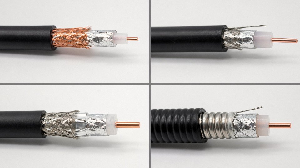
The first is the aluminum-foil tape — typically a mylar-bonded laminate wrapped around the dielectric with 100% longitudinal coverage, no gaps. That continuous metallic layer is what actually blocks high-frequency fields from passing through the cable wall. The foil handles the electromagnetic shielding function. It’s effective, but it’s mechanically fragile; flex it repeatedly at a tight bend and you’ll crack it, usually right behind a connector where nobody sees it until the signal problem shows up.
The braid is the second element — aluminum strands woven in a helical pattern over the foil. It adds shielding depth, provides the mechanical path that survives repeated flexion, and gives the connector something to grip. Braid coverage is stated as a percentage of the underlying surface it actually covers, and this is where specs diverge meaningfully: a nominal 60% braid is not the same animal as a 77% braid, even if they’re both sold as “dual-shield RG-6.”
Combined shielding performance is expressed as shielding effectiveness in dB — essentially how much the cable attenuates an unwanted signal trying to get in or out. The two-layer system is what makes that number meaningful at cable TV frequencies.
Dual Shield vs. Quad Shield: When the Difference Matters
Dual-shield construction (one foil, one braid) is the standard for most residential cable TV work. At 1 GHz, a well-made dual-shield RG-6 with 77% braid coverage achieves roughly 75–90 dB of shielding isolation, depending on connector quality and termination workmanship. That’s adequate for a single-family home in a suburban environment, and specifying quad shield there is spending money you don’t need to spend.
Quad-shield cable adds a second foil and a second braid layer. Shielding isolation climbs to 100–110 dB at 1 GHz. That jump isn’t incremental — it represents a fundamentally different noise floor for the cable run.
Quad-shield RG-6 coaxial cable achieves 100–110 dB shielding isolation at 1 GHz, compared to 75–90 dB for dual-shield construction.True
These ranges reflect standard industry specifications for 75-ohm coaxial cable shielding effectiveness, consistent with SCTE/ANSI cable standards and manufacturer data sheets for CATV-grade RG-6.
FCC Part 76 Leakage Requirements and Where They Bite You
FCC Part 76 sets cable leakage limits for CATV operators. Signal egress above 15 dBmV measured at the cable surface constitutes a violation — not a threshold to push against, a hard regulatory line. In RF-dense environments like airports, hospitals, or dense urban corridors where cable runs pass near aeronautical navigation bands or medical telemetry frequencies, even a modestly degraded dual-shield connection can produce measurable leakage. Operators who’ve gone through an FCC cumulative leakage index audit know how quickly individual small violations across a large MDU plant add up to a systemic compliance problem.
Quad shield is the practical answer here. It’s not theoretical overkill — it’s the specification that keeps a leakage audit from turning into an enforcement notice.
Ingress: The Problem That Shows Up in Your Upstream
Egress gets the regulatory attention, but ingress is what actually degrades service quality in modern HFC networks. The upstream return path sits between 5 and 42 MHz in legacy DOCSIS systems, widening to 5–85 MHz in DOCSIS 3.1 extended spectrum configurations. That band is crowded with amateur radio, shortwave, and — increasingly — subharmonic noise from LTE and 5G base stations operating above 700 MHz that couples into poorly shielded cables as broadband noise.
Inadequately shielded coax in an urban installation doesn’t just leak your signal out. It acts as a receiving antenna, and whatever noise it picks up lands directly in the upstream band. Cable modem upstream performance degrades, packet error rates climb, and the modem retransmits, which a CMTS sees as a marginal plant. The actual cause — shielding inadequacy rather than amplifier alignment or tap levels — can take a field technician a frustrating amount of time to isolate.
A Practical Field Specification Rule
In single-family residential installs without nearby RF emitters, RG-6 dual shield is sufficient. The economics make sense, installation is straightforward, and a properly terminated dual-shield run holds the upstream clean.
The calculus changes in MDUs, hospitality properties, healthcare facilities, or any deployment within roughly 500 meters of a cellular base station. In those environments, specify quad shield as the default from the beginning of the project — not as a retrofit after the first noise complaints come in. Re-pulling cable through conduit in a finished hotel corridor costs multiples of whatever you saved on the original cable spec.
Jacket and Dielectric Material Selection for Indoor, Outdoor, Burial, and Plenum Runs
Jacket and dielectric choices are where a technically sound cable selection can still go wrong — and where field failures are most likely to be misdiagnosed as a shielding or connector problem long after the real culprit is a degraded outer jacket or a dielectric that’s absorbed moisture it was never designed to shed.
Jacket Materials by Installation Environment
Standard PVC works fine for indoor, dry, conditioned spaces. It’s flexible, cost-effective, and widely stocked. The limitation is its temperature ceiling — typically 60°C — and its behavior under UV exposure, which is essentially zero tolerance. Leave PVC-jacketed coax lashed to an aerial strand on a rooftop, and you’ll see cracking and embrittlement within one to three seasons depending on climate. A dark-colored cable in direct summer sun in Arizona, Texas, or a comparable high-insolation region can reach surface temperatures of 70–80°C, which means a standard PVC jacket is operating at or beyond its rated limit every clear afternoon for months at a time. The correct spec for aerial runs — full stop — is UV-stabilized black polyethylene (PE) or linear low-density polyethylene (LLDPE), rated to 80–90°C. The carbon-black UV stabilizer in these jackets isn’t cosmetic; it’s the difference between a 20-year aerial lifespan and a 3-year replacement cycle.
For direct-burial applications, the jacket requirement doesn’t change — PE or LLDPE still — but the cable construction needs to go further. A plain jacket against wet soil will eventually allow moisture migration through micro-voids, especially in cables with foamed dielectric. Flooded-gel filling (a petroleum-based compound that fills the interstices between jacket and dielectric) or longitudinally applied water-blocking tape stops that migration path. Without one or the other, you’re looking at dielectric constant drift and increased attenuation in as little as two to five years in consistently wet ground. Gel-filled cable is messier to terminate — anyone who’s wrestled with a Belden 1694F burial variant on a cold morning knows exactly what that means — but it’s the right construction for the application.
Dielectric Construction and Its Direct Effect on Signal Performance
The dielectric isn’t passive. Solid polyethylene carries a dielectric constant of roughly 2.25 and a velocity of propagation (VOP) around 66%. Foamed or cellular polyethylene — where the material is expanded with nitrogen or a chemical blowing agent to introduce air voids — drops the dielectric constant to approximately 1.4–1.5 and raises VOP to 82–85%, depending on foam density. That VOP increase matters for two reasons: phase delay is reduced (relevant in longer distribution runs where timing relationships between signals can degrade system performance), and attenuation drops meaningfully across the full DOCSIS frequency range. In a 200-foot horizontal drop, the difference between solid and foamed dielectric coax is real enough to affect signal margin at 750 MHz and above. Specify foamed dielectric for any run longer than roughly 100 feet or any application operating above 600 MHz.
Plenum Ratings and Code Designations
NEC and CEC both define cable type designations that carry legal weight during inspection. The four you’ll encounter in cable TV work: CATV (standard, for general use), CATV-P (plenum-rated, required in air-handling spaces under NFPA 90A), CATV-R (riser-rated, for vertical runs between floors), and CATV-X (general use, a lighter classification). Plenum spaces — return-air ceilings, raised-floor data environments, HVAC plenums — require CATV-P. The jacket material is typically FEP (fluorinated ethylene propylene) or a low-smoke, low-flame PVC compound. The logic isn’t performance; it’s smoke toxicity in an occupied building during a fire.
Installing standard CATV-rated coaxial cable in a plenum space without CATV-P rating is a code violation under NFPA 90A, regardless of how well the cable performs electrically.True
NFPA 90A Section 4.3 prohibits the use of non-plenum-rated cables in air-handling spaces. An electrically excellent cable with a standard PVC jacket will fail inspection and may create legal liability in the event of a fire, irrespective of signal performance.
Using a lower-rated cable in a plenum to save $0.10 per foot is one of those procurement decisions that looks fine until the inspection or, worse, until it isn’t.
Messenger Wire Construction for Aerial Spans
Self-supporting figure-8 cable — where a steel messenger wire is bonded to the cable jacket at the factory — eliminates the need for separate lashing wire and a lashing machine during aerial installation. Labor savings run roughly 30–40% compared to lashing separate coax to a strand, which matters on any project with significant pole-to-pole runs. For spans beyond about 100 feet, figure-8 messenger construction is effectively standard practice; without it, sag calculations and mechanical tension become real engineering concerns rather than rough estimates. The messenger steel gauge should be matched to the span length and expected ice/wind load — a detail that gets glossed over in procurement until the first ice storm pulls a run off the poles.
Drop Cable vs. Distribution Cable vs. Trunk Cable: Matching the Wire to the Network Segment
Anyone who has spent time on an HFC plant knows that specifying “coaxial cable” on a purchase order without qualifying the network segment is a fast way to receive the wrong product on a job site. Trunk cable, distribution cable, and drop cable are three distinct product categories with different physical construction, connector systems, and performance targets. Mixing them up — or assuming RG-6 covers every leg of the network — will cost you in rework, signal margin, or outright field failures.
Trunk Cable: The Backbone Run
Trunk cable runs from the headend (or optical node output) out to the primary amplifier cascade. These are hardline cables — typically 0.500-inch or 0.750-inch outside diameter — built around a solid aluminum outer conductor that is drawn seamlessly and sometimes corrugated to allow controlled bending without compromising the RF envelope. The dielectric is either a foamed polyethylene or a corrugated air-space design, both of which keep the velocity of propagation high and attenuation low. At 1 GHz, a quality 0.500-inch trunk hardline will come in somewhere between 0.18 and 0.28 dB per 100 feet depending on the manufacturer’s dielectric design and the aluminum alloy spec — that’s roughly five to seven times lower than RG-6 at the same frequency. Over a 500-foot trunk run, the difference between using hardline and flexible coax would be enough to wipe out your entire node-to-amplifier signal budget.
That aluminum outer conductor also serves a mechanical function. In aerial plant it provides rigidity under messenger wire loading; in direct-buried runs it resists soil pressure and maintains dimensional stability over decades.
Distribution Cable: Node to Tap
Between the amplifier node and the distribution taps sits distribution hardline — typically 0.412-inch or 0.500-inch — which follows the same basic construction as trunk cable but is often deployed in shorter, more branched runs through neighborhoods. Attenuation values are slightly higher than trunk cable (the smaller the diameter, the higher the loss), but still well below any flexible coax option. Expect roughly 0.25–0.40 dB per 100 feet at 1 GHz for 0.412-inch distribution hardline, depending on dielectric construction and frequency.
One thing that catches inexperienced crews: hardline cable does not terminate with standard F-connectors. It uses hardline connector systems — pin-and-socket designs, snap-in connectors, or swept-entry connectors depending on the tap or amplifier housing — and fitting these correctly requires manufacturer-specific tooling and trained splicing personnel. A field crew accustomed to residential drop work cannot simply pick up a hardline job without additional training. The consequence of poorly fitted hardline connectors isn’t just a marginal signal loss; it’s water ingress at the interface, corrosion inside the outer conductor, and eventually a service-affecting failure that is expensive to locate and repair.
Drop Cable: Tap to Premises
The drop is where RG-6 and RG-11 live. For a standard residential drop under roughly 150 feet, RG-6 with a solid copper-clad steel center conductor and quad-shield construction is the correct call — it handles the signal budget comfortably and is easy to work with in the field. When the drop extends to 150–300 feet (a long driveway, a detached outbuilding, some MDU scenarios), RG-11 becomes the practical choice. Its larger 0.412-inch-range outer diameter and lower attenuation — typically in the 1.0–1.5 dB per 100 feet range at 1 GHz versus RG-6’s 1.5–2.5 dB — preserve enough signal margin to close the link without amplification.
For drops exceeding 300 feet, most experienced contractors prefer a small in-line drop amplifier on RG-6 over switching to an even larger or stiffer cable. Flexibility in routing through attics, crawl spaces, and conduit bends matters more in practice than the theoretical gain of stepping up conductor diameter.
CATV-grade quad-shield RG-6 with factory-installed compression F-connectors reduces field labor time on large residential and MDU drop installations compared to field-terminated loose cable.True
Pre-terminated assemblies eliminate the field crimping or compression step, reduce connector installation errors, and allow faster pull-and-connect sequences. On large MDU programs with hundreds of drops, the cumulative labor reduction is typically 25–35%, depending on crew skill level and job layout.
For bulk residential and MDU drop programs, Jinda supplies CATV-grade quad-shield RG-6 with factory-installed compression F-connectors as a standard offering. Pre-terminated assemblies cut field labor by 25–35% on large installs — the savings come from eliminating per-drop connector prep time and reducing installation errors that require rework. On a 400-unit MDU project, that difference is meaningful enough to factor into your bid.
Installation Best Practices That Preserve Wire Performance in the Field
Specifying the right cable is half the job. The other half happens on the ladder, in the crawlspace, and at the connector block — and that half is where most signal problems actually originate. A quad-shield RG-6 with solid copper conductor can be turned into a mediocre performer in about thirty seconds by someone who bends it wrong around a joist or grabs a bag of push-on connectors because they were cheaper at the supply house.
Bend Radius: The Rule That Gets Ignored Most Often
RG-6 should not be bent tighter than roughly 2 inches of radius during installation — that works out to about 10 times the cable’s outer diameter, which for a typical 6.9 mm OD drop cable puts you right around that 2-inch figure. Tighter than that and you’re physically deforming the foam dielectric, which changes the velocity of propagation locally and creates an impedance discontinuity at that point. The result shows up on a sweep as a standing-wave notch — a dip in the frequency response that’s permanent, not something you can fix by re-terminating the connector. In practice, the worst offenders are tight pulls through conduit bends and cable stapled hard against inside corners of wall framing. A cable stapler with too much pressure is almost as bad as a sharp bend; it can oval the cable and produce the same effect over a short crushed section.
RG-11, being stiffer and larger in diameter, needs even more attention here. Minimum bend radius on RG-11 trunk and feeder runs is typically 10–12 times OD, depending on the manufacturer’s spec sheet — don’t assume the same 2-inch figure applies.
Connector Termination: Compression vs. Crimp vs. Push-On
This is not a close contest. Compression F-connectors, when properly seated with a calibrated compression tool, produce a 360-degree radial clamp on the braid and outer jacket that holds the dimensional geometry of the cable end stable. Return loss above 30 dB at 1 GHz is achievable with quality compression connectors on good cable prep. Crimp connectors are adequate for runs that stay below roughly 750 MHz — older analog CATV or low-channel satellite IF — but the single-crimp geometry doesn’t maintain the same contact consistency at higher frequencies, and you’ll see degraded return loss above that range.
Push-on connectors have no place in any permanent installation. They rely on spring tension against the center conductor and have no reliable mechanical retention on the outer conductor. Vibration, thermal cycling, and any cable movement will eventually introduce intermittent contact. Use them for bench testing if you want, but not in a wall or on a pedestal.
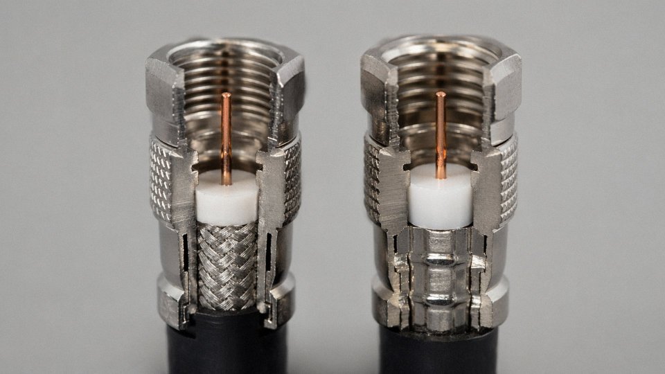
Proper cable prep matters just as much as connector choice. The dielectric should be trimmed cleanly without nicking the center conductor, the braid should be folded back cleanly and evenly, and the foil should remain intact and not bunched. A folded or torn foil underneath the connector body is one of the more common sources of high-frequency shield degradation that doesn’t show up obviously on a visual inspection.
Compression F-connectors achieve better return loss than crimp F-connectors at frequencies above 750 MHzTrue
The circumferential clamp of a compression connector maintains more consistent geometric contact with the cable's outer conductor than a single-crimp deformation, which is why SCTE and most MSO installation standards specify compression connectors for DOCSIS 3.0 and 3.1 plant.
Grounding Per NEC Article 820
The coaxial shield must be grounded at the building entry point using a listed grounding block connected back to the building’s grounding electrode system. This isn’t optional, and it’s not just a code formality — it’s the primary protection against lightning-induced transient energy reaching customer equipment and headend electronics. Failure to ground at entry is consistently among the top causes of modem and set-top box failures after electrical storms in regions with high lightning incidence.
The grounding conductor from the block to the electrode should be as short and straight as practical, ideally 18 AWG or heavier, with no sharp bends that would increase inductance and reduce the conductor’s effectiveness at dissipating fast transients. If the nearest grounding point is the electrical panel’s ground bus, that connection needs to be made with listed hardware — a wire-nutted splice to a random grounded conductor does not meet Article 820 intent and won’t pass inspection.
Weatherproofing Outdoor Connector Points
Any F-connector exposed to weather needs to be sealed after termination. Self-amalgamating (self-fusing) tape wrapped from the cable jacket over the connector body and back provides moisture exclusion equivalent to IP67 when applied with proper overlap and stretch. Without it, connectors in humid or coastal environments typically develop oxide films on the pin contact and inside the port within 12–18 months. That oxidation adds somewhere between 5 and 15 ohms of contact resistance depending on severity — enough to produce a measurable signal drop and, in a digital system, packet errors that present as pixelation or modem instability rather than an obvious dead signal.
Dielectric grease as an alternative provides some protection but tends to attract particulate contamination over time and doesn’t perform as reliably as a proper tape wrap. Use the tape.
Splitting Loss and Drop Budget Math
Every passive two-way splitter introduces roughly 3.5 dB of insertion loss; a four-way splitter runs approximately 7 dB. Those figures are relatively consistent across quality passive splitters, though a cheap splitter can add another 0.5–1 dB above that, particularly at the upper end of the DOCSIS 3.1 spectrum near 1 GHz.
The discipline that gets skipped most often is actually adding up the cumulative loss across all splitters and cable runs before finalizing a drop design. The subscriber outlet signal needs to land within the –6 dBmV to +15 dBmV window defined by SCTE standards. If a technician adds a two-way splitter in a closet to serve a second room and nobody recalculates, an outlet that was already marginal at –4 dBmV ends up at roughly –7.5 dBmV — below the floor, and the customer complains about intermittent connectivity that took three truck rolls to trace back to an unsanctioned splitter.
Draw the loss budget on paper before the installation, not after.
Frequently Asked Questions About Cable TV Wire Selection
Can I use RG-59 for cable TV if I already have it installed?
For purely legacy analog cable TV running below 400 MHz, RG-59 will work — it was the industry standard before DOCSIS and digital tier expansion pushed signal frequencies higher. The problem is that almost no modern cable system operates in that narrow a band anymore. DOCSIS 3.1 plants push signals up past 1 GHz, and even basic digital cable packages routinely occupy spectrum above 500 MHz. At those frequencies, RG-59’s attenuation of roughly 3.0–4.5 dB per 100 feet (depending on conductor quality and temperature) bleeds signal fast. A 75-foot run that looked acceptable on an analog set will produce pixelation, dropped packets, or outright modem sync failures on a digital system.
The only reliable fix is replacement with RG-6. There is no amplifier trick that fully compensates for cable attenuation across a broadband spectrum — amplifiers add gain but also add noise, and you cannot amplify your way out of a bad cable without degrading signal-to-noise ratio in the upstream path. Pull new RG-6 quad-shield if you can; dual-shield minimum.
What is the maximum run length before I need an amplifier?
With RG-6 dual-shield, plan on roughly 100–130 feet from the tap or splitter to the outlet as your practical unamplified ceiling at 1 GHz. That range depends on conductor material (bare copper runs longer than CCS by a meaningful margin), ambient temperature, and how many passive splitters are in the path. Each two-way split costs you approximately 3.5 dB.
RG-11 extends that ceiling to around 200–250 feet before amplification, which is why it shows up on longer home-run backbone segments and in MDU riser closets. If you’re beyond either of those limits, you need an in-line distribution amplifier rated for 5–1,000 MHz pass-through, not a simple one-port booster. Confirm the amplifier passes the full downstream and upstream bands — some cheaper units block the upstream return path, which kills DOCSIS internet even when downstream TV looks fine.
Is there a difference between satellite coax and cable TV coax?
Physically, both are RG-6, and they look identical in the bag. The distinction is frequency rating. Satellite systems — particularly DirecTV SWM setups and Dish Network equipment using DiSEqC switching — use signals up to roughly 2,150 MHz for transponder selection and power delivery to the LNB. A cable TV coaxial rated only to 1 GHz will show measurable signal loss above that point, which translates to missing satellite channels or unreliable SWM communication.
Always check the cable’s swept-frequency rating on the reel label or datasheet before pulling it for a satellite job. The jacket color (white versus black) tells you nothing useful about the frequency rating.
Cable TV coax rated to 1 GHz will cause signal degradation on satellite systems operating above 1 GHzTrue
DirecTV SWM and Dish Network DiSEqC systems use frequencies up to approximately 2,150 MHz for LNB control and transponder selection; standard cable TV RG-6 rated only to 1 GHz exhibits increasing attenuation beyond its rated frequency ceiling, causing signal loss on these higher-frequency satellite signals.
Why does cable TV signal get worse in summer?
Coaxial cable attenuation rises with temperature — roughly 0.1% per degree Celsius, which sounds minor until you do the arithmetic on an outdoor run. A 100-foot RG-6 run at 50°C versus 20°C picks up something in the range of 0.3–0.5 dB of additional loss. That by itself usually won’t knock out a well-installed outlet, but if the signal level was already marginal in February, summer heat can push it below the minimum threshold the cable modem or set-top box will accept.
In practice this surfaces as complaints that “cable works fine in winter but goes out on hot afternoons.” The fix is either properly specifying headroom during system design or — if the plant is already built — trimming the tap value at the nearest node to compensate.
What certifications should I check when purchasing cable TV coax in bulk?
For North American projects, look for UL Listed or ETL Listed markings on the cable jacket, which confirms the sample production run was tested to the relevant NEC jacket and flammability requirements. For European Union distribution, CE marking is the baseline. On the electrical performance side, SCTE 74 covers coaxial cable specifications widely referenced by North American MSOs, while IEC 61196-1 covers the international equivalent. Neither marking on a reel label is proof of continuous quality — it means a tested sample passed, so pairing certifications with a supplier’s published production test data and an incoming inspection protocol on your end is the full picture.
Jinda cables produced for export are certified to the applicable standards for each destination market, which matters when a project’s installation contractor or end-user operator requires traceable documentation for the plant record.
How to Source Cable TV Wire for Large-Scale and International Projects
Buying a few reels from a local distributor is one thing. Sourcing 50,000 meters of RG-6 for a greenfield HFC buildout across multiple headend zones is a fundamentally different operation — and the failure modes are different too. At scale, the risk isn’t usually a single bad reel. It’s gradual, invisible batch-to-batch drift that only shows up after installation, when your swept-frequency results start trending in the wrong direction and you’re already six weeks past backfill.
The Quality Consistency Risks That Actually Bite You at Scale
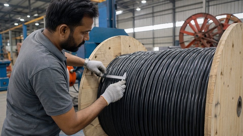
Conductor diameter tolerance is the one most procurement specs understate. A variance of ±0.01 mm across production batches — which is within the tolerance many manufacturers consider acceptable — can shift attenuation by up to 0.15 dB per 100 feet at 1 GHz. That sounds small until you’re cascading through 400 feet of drop cable and three passive splitters. It compounds.
Braid coverage variation is equally insidious. A 5% drop in braid coverage, say from a nominal 95% to around 90%, reduces shielding effectiveness by roughly 8–12 dB depending on frequency. In a dense urban MDU deployment where you’re running cable three feet from a Wi-Fi access point or a cellular DAS antenna, that kind of shielding degradation shows up as ingress on the upstream return path — exactly the channels your CMTS is trying to listen to. Field technicians chase the symptom for days before anyone thinks to pull a sample and measure the braid.
Jacket wall thickness variation is less dramatic but kills long-term durability. Thin spots in a PE or LLDPE jacket reduce UV resistance and crush resistance unevenly along the drum length. You may not see the problem until year two or three after an outdoor aerial run.
What the Documentation Package Should Actually Contain
A manufacturer who can’t provide swept-frequency attenuation test reports covering 100% of production — not sampled lots, every drum — is a supply risk on a project with contractual signal performance guarantees. Ask for it upfront. The documentation package for any serious international cable TV project should include factory test reports with swept attenuation data from 5 MHz through at least 1 GHz, third-party certification letters (UL, CE, RoHS as applicable to the destination market), material safety data sheets for the jacket compound (required for customs in several markets), and a batch traceability system that ties physical drum serial numbers back to production records. If the supplier hesitates on any of those, that tells you something.
Jinda provides 100% swept-frequency attenuation test reports per production drum and maintains batch traceability linked to drum serial numbers for international cable TV supply contracts.True
This is consistent with Jinda's stated quality documentation capabilities for export projects and aligns with standard practice for compliant HFC cable supply.
Jinda’s Supply Capabilities for Large Cable TV Projects
Shandong Jinda Special Cable Group operates five production bases across China, with 470,000 m² of total manufacturing space. In-house wire drawing and jacket compounding means the full material chain sits under one roof — conductor gauge, dielectric cell structure, braid density, and jacket thickness are all controlled without relying on third-party semi-finished inputs that introduce their own tolerance stacks. That level of vertical integration matters when you’re specifying tight attenuation windows across a large order.
For full container load orders, standard lead times run 25–45 days, depending on cable type, drum format, and current line loading. Jinda exports to more than 50 countries, so the logistics documentation — certificates of origin, packing declarations, export compliance — is routine rather than a scramble.
Reel Format and Labeling: Get This Right Before You Order
One detail that causes real procurement friction on international projects: reel format. North American projects typically expect RG-6 on 500-foot or 1,000-foot reels. European and Asian markets usually work in metric — 100-meter or 305-meter coils are standard. These aren’t interchangeable from a stocking or installation workflow standpoint, and relabeling drums in the field is a mess. Confirm reel format, drum outside diameter (it affects pallet stacking and transport), unit labeling, and language requirements before the order goes in. If the cable is going into a project with local inspection authority involvement, confirm whether CE marking or country-specific marks need to appear on the drum label itself.
Working With Jinda as a Technical Partner, Not Just a Vendor
The most efficient path for a large cable TV procurement isn’t sending a generic RFQ and waiting for a price sheet. Jinda’s engineering team can review your signal distribution design — headend output levels, cascade depth, tap values, frequency plan — and confirm which cable specification actually fits before you commit to a full production run. That review catches mismatches early: wrong impedance for a specific connector type, braid spec that won’t pass the operator’s upstream noise threshold, jacket material that doesn’t meet local fire code for the indoor portion of the run.
If you have a project coming up, send Jinda your cable schedule and system schematic. Request samples before committing to volume, confirm the documentation package meets your project’s requirements, and get bulk pricing tied to a specific specification — not a generic product code. That’s how a cable procurement goes from a supply risk to a solved problem.