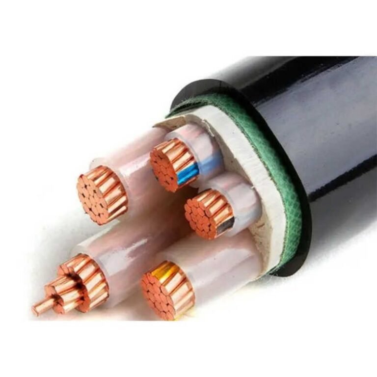
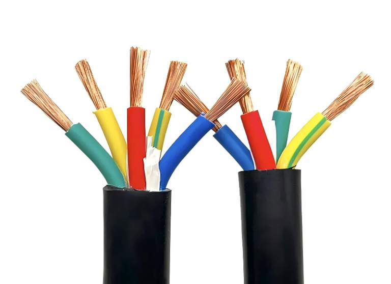
Specifying the wrong cable for an exposed run — or assuming any armored cable will hold up just because it has armor — is one of those mistakes that rarely shows up immediately. The armor protects the conductors from crush and impact, yes, but an unprotected PVC outer sheath left in direct sunlight starts losing tensile strength within two to three years, sometimes faster in high-UV climates. By the time the jacket is visibly cracking, moisture has likely been wicking into the cable for months. Rewiring an exposed outdoor run mid-project, or chasing an intermittent fault in a tray that should have been a five-year-and-forget installation, costs far more than the upcharge for a UV-stabilized sheath would have.
Yes, armored cable can be exposed — above ground, in open cable trays, on exterior walls, or in direct sunlight — but only if the outer sheath material and armor type are correctly matched to the specific exposure conditions. A standard PVC-jacketed SWA cable is not automatically suitable for prolonged UV exposure, high-temperature environments, or corrosive atmospheres. The armor handles mechanical threats; the sheath handles environmental ones. Both selections matter independently.
What makes this genuinely complicated in practice is that “exposed” covers a wide range of installation conditions — a shaded outdoor tray is nothing like a rooftop cable ladder in a coastal petrochemical plant — and the standards, sheath options, and armor configurations each address different parts of that problem. The following sections work through the key decisions.
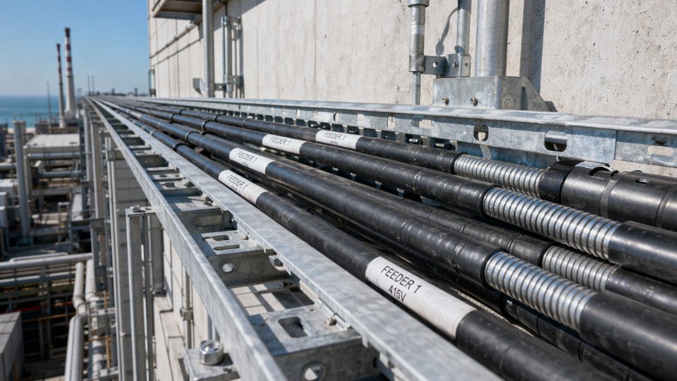
Armor Type Selection: SWA, STA, DSTA, and AWA Compared for Exposed Runs
Picking the wrong armor construction for an exposed run isn’t just a spec oversight — it shows up as premature jacket cracking, corroded wires at a termination, or a ground-fault relay that fails to clear because the armor wasn’t properly bonded. Here’s how the main constructions stack up in practice.
Steel Wire Armoring (SWA)
SWA is the workhorse: individual galvanized steel wires applied helically over the inner sheath, conforming to IEC 60502-1 and BS 5467. Crush resistance runs roughly 450–900 N/cm depending on cable diameter and wire gauge — a 35 mm² four-core will sit toward the lower end of that range; a 185 mm² multicore pushes toward the upper end. For exposed cable tray runs with heavy mechanical traffic (think a busy maintenance corridor where people roll equipment across trays), SWA is the default. It also handles direct burial well because it resists point loads from rock backfill. The galvanizing holds up in normal industrial atmospheres, but don’t count on it indefinitely in salt spray or chlorine-heavy air — more on that below.
STA and DSTA
Steel tape armoring uses flat steel tape wound in a tight helix, and DSTA adds a second tape wound in the opposing direction. Both are lighter than SWA, which matters when you’re mounting cable to a wall bracket or running through a conduit-free surface installation and don’t want the support spacing to become a structural engineering problem. Crush resistance is lower — 300–600 N/cm across the range — so these aren’t the right call for routes with serious mechanical abuse. For indoor surface runs in switchrooms, motor control centers, or along structural steelwork inside a building, DSTA is common and entirely adequate. The double-tape construction also gives better resistance to lateral shear than single tape, which is relevant if the cable runs across expansion joints or through areas with minor vibration.
Aluminum Wire Armoring (AWA)
Single-core cables are a different problem. Wrap a single-core cable in a closed steel armor and you create a shorted turn: alternating current in the conductor induces circulating currents in the steel, generating heat and wasting energy. AWA solves this — aluminum wires have high enough resistivity to suppress those circulating currents to acceptable levels. Beyond that electrical reason, AWA has genuine corrosion advantages in coastal installations or anywhere with atmospheric chlorides or chemical splash. Aluminum forms a stable oxide layer rather than rusting through. In practice, I’ve seen SWA cables on marine jetties where the armor was essentially lace within five years; the same route with AWA, properly terminated, was still serviceable at fifteen.
Aluminum wire armoring (AWA) is the standard choice for single-core power cables because steel armor would cause unacceptable eddy current heating.True
A closed magnetic path around a single-phase AC conductor induces circulating currents in ferromagnetic armor. IEC 60502-1 and most national standards require non-magnetic armor — typically AWA or aluminum tape — for single-core cables above a few dozen amps to avoid this.
Interlocked Armor (NEC Article 330 Type MC)
In North American markets, interlocked armor — a continuous strip of formed aluminum or steel mechanically interlocked in a spiral — is the standard for exposed surface wiring in commercial and industrial buildings. It’s flexible enough to route through tight bends without conduit and can be field-cut and terminated quickly. It doesn’t match SWA for brute crush resistance, but for exposed runs along walls, ceilings, and equipment frames inside facilities, it’s efficient and code-compliant. Governed by NEC 330 rather than IEC 60502 or AS/NZS 1429, so procurement teams sourcing for cross-market projects need to track which standard the end-use jurisdiction requires.
Comparison at a Glance
| Armor Type | Crush Resistance | Corrosion Resistance | Flexibility | Relative Weight | Key Standards | Typical Exposed Application |
|---|---|---|---|---|---|---|
| SWA | 450–900 N/cm | Moderate (galvanized) | Low | High | IEC 60502-1, BS 5467 | Cable tray, direct burial, heavy industrial |
| STA | 300–600 N/cm | Moderate | Low–Moderate | Medium | IEC 60502-1, BS 5467 | Indoor surface runs, switchroom wiring |
| DSTA | 300–600 N/cm | Moderate | Low–Moderate | Medium | IEC 60502-1, BS 5467 | Indoor surface, vibration-prone routes |
| AWA | 400–750 N/cm | Good (oxide layer) | Low–Moderate | Medium-Low | IEC 60502-1, BS 5467, AS/NZS 1429 | Single-core MV/LV, coastal/chemical environments |
| Interlocked (MC) | Lower than SWA | Moderate–Good (Al strip) | High | Low–Medium | NEC Article 330 | North American exposed commercial/industrial |
Armor Continuity and Ground-Fault Protection
This is the part that gets skipped at commissioning and causes problems later. In exposed runs, the armor frequently serves as the equipment grounding conductor — which means termination quality directly affects fault-clearance performance. A loose gland or an unbonded armor at one end raises the impedance of the fault return path, and depending on the circuit’s protective device settings, a ground fault may not clear fast enough. IEC 60364 and NEC both have explicit bonding requirements at each termination point. Use glands rated and tested for armor continuity (not just cable retention), bond at both ends unless your design intentionally breaks the circuit to prevent circulating currents in certain AWA single-core arrangements, and verify continuity with a low-resistance ohmmeter before energizing. In practice, this step gets skipped under schedule pressure more often than it should.
Sheath and Jacket Materials That Determine Outdoor and Chemical Exposure Performance
Here is where most specification errors happen. Engineers select the armor carefully — SWA for direct burial, AWA for tray runs — and then accept whatever sheath material shows up on the standard product offering without thinking hard about it. The armor protects against mechanical damage. The sheath is doing almost everything else: blocking UV photodegradation, resisting ozone cracking, preventing moisture ingress to the armor layer, and holding out against chemical splash. Get the sheath wrong and you can have a perfectly armored cable that fails its outer jacket within three to five years.
PVC: Acceptable Indoors, Problematic Outdoors
Standard PVC outer sheaths are the default for a reason — they are cost-effective, flexible down to around -15°C, and perfectly adequate for sheltered indoor exposed runs like cable ladders inside a dry factory or a warehouse. The 70°C continuous rating covers most industrial environments comfortably. The problem is UV exposure. Unprotected PVC loses plasticizer over time; the sheath becomes brittle, develops surface crazing, and eventually cracks, which opens a direct moisture path to the armor. In direct outdoor sun, without a UV stabilizer additive, you’re realistically looking at 30–40% tensile strength loss within 2–3 years and a service lifespan of roughly 5–10 years before the sheath needs attention.
Standard PVC outer sheaths without UV stabilizer additives will degrade significantly faster than UV-stabilized polyethylene sheaths in direct outdoor sun exposure.True
PVC plasticizer migration under UV and heat causes embrittlement and cracking. UV-stabilized HDPE sheaths, by contrast, are specifically compounded to resist photo-oxidation and can achieve 20–25 year outdoor service life per IEC 60502-2 specifications.
If the project is an outdoor cable tray run on a rooftop or a coastal substation, a plain PVC sheath is the wrong call regardless of how good the armor is.
UV-Stabilized HDPE and MDPE: The Default for Any Outdoor Exposed Run
For outdoor exposed installations — open tray, cable bridge, surface-mounted conduit in the elements — UV-stabilized HDPE or MDPE sheath is what you want specified from the start. These materials are compounded with carbon black or chemical UV stabilizers that absorb and dissipate UV radiation rather than letting it attack the polymer chains. Service life extends to 20–25 years in typical outdoor conditions, and resistance to ozone and moisture ingress is significantly better than PVC. IEC 60502-2 Type ST2 and ST7 sheaths sit in this category. The thickness matters, too: per IEC 60811, sheath thickness tolerances are tightly defined, and undersized sheaths — even by half a millimeter — reduce the thermal buffer in high-ambient environments and accelerate UV fatigue at the surface. In practice, request mill certificates confirming sheath thickness measurements taken per IEC 60811-1-1; nominal is not always actual on lower-tier supply.
LSZH: Non-Negotiable in Enclosed Public Routes
Low Smoke Zero Halogen sheath material is not an upgrade — it is a requirement for tunnels, metro and rail systems, airport terminals, and any enclosed public building where exposed cable runs cannot be allowed to emit toxic halogen gases in a fire. The 90°C continuous temperature rating gives useful headroom for high-load circuits. Cost is higher, 15–30% above equivalent PVC sheathed cable depending on cable size and order volume, but in these applications there is no compliant alternative. Specifying standard PVC on an exposed metro tunnel run will fail the fire safety review.
PU and Neoprene for Harsh Industrial Exposure
Polyurethane and neoprene sheaths handle the environments that chew through everything else. Mining drift cables, offshore platform runs, petrochemical plant areas with constant hydrocarbon splash — these applications involve mechanical scuffing against rough surfaces, oil contamination, and sometimes repeated flexing. PU sheaths absorb abrasion far better than PVC or HDPE; neoprene offers both oil resistance and good flame retardancy without the cost of full LSZH compound. Neither is the default choice for static installations, but for trailing cables or exposed runs in processing areas, they are worth the premium.
Sheath Color: More Than Visual Coding
Black sheath is standard for outdoor UV-resistant applications because carbon black is itself a UV stabilizer. Orange is widely used for high-voltage warning identification. Red sheaths indicate fire-resistant circuit cables in many regional codes. This matters operationally: maintenance crews making fault-finding decisions under pressure use color as a first filter, so a non-standard color from a replacement spool can create real confusion. Jinda customizes sheath color to project specifications or regional code requirements, which is worth confirming at the order stage rather than discovering a color mismatch on site during installation.
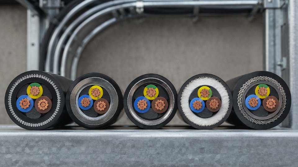
The short version: armor decides whether the cable survives mechanical abuse. Sheath decides whether it survives the environment. Both decisions need to be made deliberately.
Code and Standards Compliance for Exposed Armored Cable Installations
Specifying armored cable for an exposed run is only half the job. Getting the installation signed off — by an inspector, an insurer, or a client’s commissioning team — requires matching the cable construction to the governing standard for that jurisdiction. The standards don’t always agree, and on international projects that’s where engineers lose time.
IEC 60364-5-52: The Foundation for Most Markets Outside North America
IEC 60364-5-52 Table B.52.1 defines installation methods B1 through F, each carrying its own current-carrying capacity basis and correction factors. Method C (single cable clipped direct to a non-combustible surface) and Method E/F (cables in free air, touching or spaced) are the two you’ll encounter most on exposed industrial runs. The difference matters: a 95 mm² armored cable on a cable tray in free air (Method F) typically carries 15–20% more current than the same cable clipped flat against a wall (Method C), depending on grouping and ambient temperature. Correction factors compound quickly — a tray with six touching cables in a 45°C ambient can reduce rated ampacity by 40% or more compared to the nameplate figure. Apply them before you size conductors, not after.
NEC Articles 330 and 334: The North American Distinction
Under NFPA 70, MC Cable (Article 330) is the armored cable type permitted for exposed runs in US commercial and industrial work. It may be installed exposed on walls, ceilings, and cable trays provided it is supported at intervals not exceeding 1.8 m (6 ft) and within 300 mm (12 in) of every box or fitting. The critical restriction: where MC Cable is subject to physical damage — typically interpreted as any exposed run below 2.5 m (8 ft) in areas with fork-lift or vehicle traffic — it must be protected by conduit, cable tray with covers, or another approved means. NM Cable (Article 334) is a different story altogether; it is explicitly prohibited in exposed locations where it will be subject to physical damage, and using it outdoors or in wet locations without the correct listing is a common inspection failure on smaller industrial fit-outs.
BS 7671 18th Edition: Accessible Versus Inaccessible Routes
Chapter 52 of the IET Wiring Regulations draws a line that IEC 60364 handles less explicitly: the distinction between an exposed cable route that a person can readily reach and one that isn’t ordinarily accessible. For accessible routes, the mechanical protection requirements tighten, and armored cables installed in those locations must have their armor earthed at both ends in most configurations. Cable selection tables in Appendix 4 apply grouping and thermal insulation factors that, in practice, often force engineers to upsize by one conductor cross-section when cables run surface-mounted in bunches.
GB/T 12706 and GB 50054: Industrial Installations in China
GB 50054 specifies fastening intervals for exposed cable runs in industrial facilities — generally 1.0 m on horizontal runs and 1.5 m on vertical runs for cables above 16 mm² cross-section, though the exact figure depends on cable weight and outer diameter. Horizontal separation between power and control cables must be maintained at ≥ 150 mm without barriers or ≥ 50 mm with a grounded metal partition. GB/T 12706 governs the cable construction itself, and project submittals for Chinese facilities typically require the cable test reports to reference this standard explicitly — a CE or KEMA mark alone is usually insufficient for domestic inspection acceptance.
AS/NZS 3008.1: Derating in Australian Conditions
The Australian and New Zealand standard takes a notably conservative approach to exposed installations. Cables in enclosed conduit outdoors are derated more aggressively than cables in open air, because conduit traps heat — a fact that surprises engineers used to thinking of conduit as purely protective. Armor construction affects this: armored cables have slightly higher thermal resistance than unarmored equivalents of the same cross-section, so the derating tables for armored types in AS/NZS 3008.1 must be used, not the unarmored columns. The difference is small on a single cable but meaningful when you’re at the edge of a conductor size.
ATEX and IECEx: Hazardous Area Obligations
Exposed armored cable in Zone 1 or Zone 2 classified areas brings in a separate layer of compliance that overrides the general wiring standards. The armor must be continuous and earth-bonded at both terminations; any break in armor continuity at a gland is a non-compliance, not a minor deficiency. Gland selection is critical — only certified Ex-rated glands with appropriate IP ratings for the zone are acceptable, and the gland must suit the armor type (SWA and AWA require different gland designs). Sealing arrangements at zone boundaries, where cable passes from a hazardous to a safe area, must comply with IECEx-certified seal fittings. Inspectors on ATEX-governed sites will pull gland certifications during commissioning; having the cable test documentation in order well in advance saves real delays.
Product Documentation and Certification Packages
Jinda’s manufacturing and testing infrastructure — ISO 9001 quality management, ISO 14001 environmental certification, KEMA type test approvals, CE marking, and CCC certification for domestic Chinese supply — means that project engineers submitting compliance packages across multiple jurisdictions can request a single coordinated documentation set rather than chasing test reports from separate sources. For projects that span both a European and a Southeast Asian component, for example, having IEC type-test data and CCC certificates from the same production batch simplifies the submittal review considerably.
Armor continuity at both cable ends is mandatory for ATEX Zone 1 and Zone 2 exposed installations.True
IECEx and ATEX standards require armor to be bonded to earth at both terminations to maintain the equipotential bonding and fault-current return path required in explosive atmospheres. A floating armor end is a certification failure, not a minor deficiency.
Mechanical Protection Ratings and Physical Routing Rules for Surface-Mounted Armored Cable
Surface-mounting armored cable sounds straightforward until you’re standing on a plant floor watching a maintenance crew bend a 35 mm² SWA around a tight corner with a pipe bender, or find a run sagging between cleats spaced a meter and a half apart because someone ran out of fixings. The armor doesn’t forgive sloppy installation — it just fails quietly, often years before anyone notices.
Minimum Bend Radius and What Happens When You Ignore It
The standard working figure is 8× the overall cable diameter for SWA during installation, and 6× for STA cables. Those multipliers exist because steel wire armor behaves differently under bending stress than steel tape: individual wires can redistribute tension along their helical lay, whereas tape armor has almost no ability to accommodate differential strain at tight bends. Go below those limits and you’re not just creasing the armor — you’re fatiguing the wires at the bend apex, which creates micro-cracks that propagate under thermal cycling. The insulation underneath suffers too; XLPE and even PVC cores compressed against a bent armor layer develop localized stress points that eventually crack. In practice, the damage often doesn’t show up on an initial continuity check. It shows up 18 months later as an intermittent earth fault during a wet season.
Support Intervals and Fastening
IEC 61537 and BS 7671 both point toward supports every 300–500 mm for horizontal exposed runs, and 400–600 mm vertically, but those ranges aren’t interchangeable — they depend on cable weight per meter and outer diameter. A 4-core 25 mm² SWA weighs roughly 2.5–3 kg/m; space those cleats at 500 mm horizontally and you’re probably fine. Do the same with a 4-core 95 mm² and you’ll get visible sag within a year, which stresses termination glands and creates water traps.
Cleat material is something procurement teams often treat as an afterthought. Aluminum cleats on SWA cable in a coastal or chemically aggressive environment is a classic galvanic corrosion setup — the steel armor and aluminum cleat form a bimetallic couple that accelerates corrosion at exactly the contact point where you need mechanical integrity. Stainless steel cleats (316 grade in marine or chemical zones) or UV-stabilized nylon are the right call. The cost difference per cleat is trivial compared to the cost of re-running a cable tray.
Low-Height Runs and Additional Guards
Any exposed run below 1.8 m (roughly 6 ft) in an area with forklift or vehicle traffic needs supplementary protection. Most codes — IEC, NEC, and BS 7671 alike — require steel channel, conduit sleeve, or a proprietary cable protection guard in these zones. Armor handles incidental contact reasonably well; a direct forklift tine hit at ground level is a different load entirely. This is especially relevant in warehouse distribution centers and loading docks where routing options are limited.
SWA armor alone provides sufficient mechanical protection for cable runs in forklift traffic areas without additional guardingFalse
SWA armor is rated for radial crush loads of 450–900 N/cm depending on diameter, but direct vehicle impact loads in traffic areas can far exceed this. Most codes require additional mechanical protection — steel channel, conduit sleeve, or cable guard — for exposed runs below 1.8 m in vehicle traffic zones.
Tray Fill Ratios and Thermal Exposure
On perforated cable tray, IEC 61537 caps fill ratio at 40% for outdoor exposed installations. Armored cables eat into that budget fast — an SWA cable’s overall diameter runs 15–25% larger than an equivalent unarmored cable, so a tray sized for unarmored runs will overfill quickly if the design isn’t revised. Overfilled outdoor trays trap heat, reduce ampacity, and accelerate sheath aging. Leave headroom in the tray design; it’s far cheaper than de-rating or re-routing later.
Thermal Movement in Seasonal Climates
This one surprises people who work mostly indoors. Exposed outdoor armored cable runs can move 15–25 mm per 10 m of length across a 50°C seasonal temperature swing — think a facility in a continental climate cycling from -10°C in January to +40°C in July. Over a 50 m outdoor run, that’s 75–125 mm of cumulative linear movement, more than enough to stress gland entries and termination boxes if the cable is fixed dead-straight. Expansion loops or deliberate S-bends at regular intervals absorb that movement. Skipping them is one of those decisions that costs nothing to get right and a gland replacement job — plus potential water ingress — to get wrong.
Vibration Environments
Near pumps, compressors, or rail infrastructure, SWA consistently outperforms STA in service life. Wire armor distributes vibration stress along the helical lay of individual wires; tape armor concentrates stress at the tape edges and overlap joints. In a high-vibration environment, STA can develop edge fatigue cracking within a few years of service. If the cable routing passes within a few meters of rotating machinery and there’s no isolation mounting, specify SWA and document the reason — it’s the kind of decision that’s obvious in retrospect and contested in procurement reviews before the fact.
Exposed Armored Cable in Harsh Environments: Offshore, Mining, and Chemical Plant Applications
The environments covered in general installation guidance rarely prepare engineers for the cable specifications that actually get challenged in the field. Offshore platforms, underground mines, and chemical process units are different animals entirely — the degradation mechanisms are faster, the consequences of a failure are more severe, and the margin for under-specification is essentially zero.
Offshore Oil and Gas Platforms
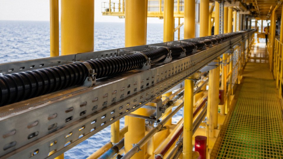
Salt spray is the issue that catches people out most often. Inland industrial sites corrode steel armor, sure, but coastal and offshore environments accelerate that oxidation by roughly 3–5×, depending on how close the cable run is to the splash zone and whether the platform is in a tropical or arctic climate (cold seawater is actually more aggressive in some corrosion modes). Standard hot-dip galvanized SWA can survive on an upper deck in moderate exposure, but for cable trays running along a lower hull or through a wellhead area, the right answer is aluminum wire armoring — AWA — combined with a neoprene or CSP (chlorosulfonated polyethylene) outer sheath. Neoprene handles the combination of UV, ozone, seawater splash, and hydrocarbon mist that’s typical on a production platform.
The governing standard for this environment is BS EN 60092-354 for shipboard and offshore fixed installations, and the test regimes it mandates — saltwater immersion, flame propagation, smoke density — aren’t paperwork formalities. Projects regularly fail inspection when engineers substitute a land-rated armored cable assuming it’s “close enough.”
Underground and Surface Mining
Mining trailing cables live a genuinely brutal life. Rock abrasion, point loads from haul truck tires, repeated flexing on drag reels, and methane atmospheres all converge in the same installation. For fixed underground runs, IEC 60702 fire-resistant construction is the baseline in most jurisdictions; for the US market, MSHA-approved cable constructions are mandatory and the approval list is specific — you can’t substitute freely.
Drag chain installations deserve particular attention because standard SWA is not designed for repeated bending cycles. You need a flexible armor construction — tinned copper braid or fine-wire interlocked armor — matched to a sheath compound that retains flexibility at the low temperatures common in underground headings. The failure mode for an incorrectly specified mining trailing cable is usually armor wire fatigue cracking, which punctures the insulation and creates an arc fault risk in a zone where that is genuinely catastrophic.
Chemical Process Plants and Refineries
PVC outer sheaths in chemical splash zones have a service life measured in months, not years. Hydrocarbon solvents swell PVC, acids attack the plasticizer system, and the sheath becomes brittle and crazed well before the cable reaches the end of its intended design life. In splash zones, specify HDPE or PVDF (polyvinylidene fluoride) outer sheath as a minimum; PVDF is the more expensive option but handles concentrated acid mist and aromatic solvent exposure that HDPE won’t. Pair that with AWA rather than steel armor in areas where chloride-containing process streams are present.
PVDF outer sheath provides significantly better chemical resistance to aromatic solvents and concentrated acids than standard PVC in refinery environmentsTrue
PVDF's high fluorine content creates strong C-F bonds that resist attack from hydrocarbons, chlorinated solvents, and strong acids — a well-established materials property, not a marketing claim.
Data Centers and Renewable Energy Sites
Raised-floor and overhead backbone runs in data halls increasingly use STA-armored OS2 fiber and Cat6A, primarily for rodent and accidental-contact protection rather than crush resistance. It’s a relatively recent specification trend and not every data center architect is familiar with the routing constraints armored fiber brings — bend radius limits in particular.
Utility-scale solar farms present a UV and thermal cycling challenge. DC string cables exposed on aluminum racking systems, sometimes in desert environments, need UV-stabilized HDPE sheath and tinned copper conductors. Tinned copper resists the oxidation that bare copper develops under repeated moisture cycling and elevated temperature, which matters because high-resistance conductor joints under DC voltage create arc fault conditions that standard AC protection schemes don’t catch cleanly.
Middle East Petrochemical Project — A Representative Supply Scenario
A useful benchmark for offshore-adjacent chemical plant specifications: a medium-voltage armored cable supply for a petrochemical complex in the Middle East, the kind of project Jinda has supplied into. Typical requirements for exposed MV cable runs in that environment include XLPE insulation rated to 90°C continuous, AWA armor with a minimum aluminum coverage of around 80–85% of the cable circumference, and an HDPE outer sheath with UV stabilizer. Third-party test reports required for project approval typically include IEC 60502-2 for power cables, a salt-spray test per IEC 60068-2-52 for the armor and sheath system, a UV aging test per IEC 60068-2-5, and a factory acceptance test witnessed by the client’s inspector. Skipping any of those qualification steps will stall approval, sometimes for months, on a project where the construction schedule has no float.
The common thread across all four environments: the outer sheath selection is where most under-specifications happen. Armor type matters, but it’s the sheath compound that determines whether the cable survives its first decade.
Current Carrying Capacity Derating When Armored Cable Is Installed Exposed
Armor protects the conductor. It also insulates it — thermally speaking — and that’s the part engineers underestimate until they’re troubleshooting a tripped breaker on a cable that looks perfectly sized on paper.
Why the Armor Layer Itself Reduces Ampacity
Steel wire or steel tape armoring adds a measurable thermal resistance between the insulation and the surrounding air. The armor layer, combined with any air gap trapped between the outer sheath and the armor bedding, increases the cable’s overall thermal resistance by roughly 5–12%, depending on armor construction, bedding thickness, and cable diameter. Larger cables — say, 185 mm² and above — sit at the lower end of that range because the armor mass is smaller relative to total cross-section. Smaller cables with proportionally thicker bedding layers can hit the upper end. The practical consequence is that an armored cable running in free air carries less current than an otherwise identical unarmored cable in the same installation method. Not dramatically less, but enough to matter when you’re already close to a conductor size boundary.
IEC 60287 and Installation Method Differences
IEC 60287 is the reference for rigorous ampacity calculation — it accounts for conductor resistance, dielectric losses, armor losses (which are real and non-trivial in single-core SWA), and the thermal resistance of each layer. For exposed armored cable, the installation method classification changes the base ampacity significantly before any derating factors are applied. Free air on a wall bracket (Method F in IEC 60364-5-52) gives the highest ampacity because convection is unrestricted. A perforated cable tray (Method E) is slightly lower — typically 5–8% depending on tray fill — because airflow under the cable is partially obstructed. Surface-mounted on a solid tray is lower still. If you’re pulling numbers from a manufacturer’s table, confirm which installation method that table assumes. Many published ratings default to Method E; applying them to a congested solid tray installation is a common source of undersized cable.
Grouping Factors: The Derating Most Often Skipped
Three armored cables touching in a trefoil surface arrangement require a 0.80 grouping factor per IEC 60364-5-52 Table B.52.20. Six cables in two layers on a tray drop to 0.68. In practice, on a busy cable tray with a mix of power and instrumentation runs, it’s not unusual to see people apply no grouping factor at all because the tray wasn’t full at the time of design — and then the plant adds three more circuits during a later expansion without revisiting the thermal calculation. That’s how you end up with insulation that ages in five years instead of twenty.
Ambient Temperature Correction for Tropical and Hot Outdoor Sites
A PVC-insulated cable rated for 100 A at 30°C ambient derate to approximately 87 A at 40°C and roughly 74 A at 50°C using standard correction factors. For exposed outdoor runs in tropical climates — Southeast Asia, the Middle East, sub-Saharan Africa — the design ambient temperature should reflect the hottest sustained condition, not an annual average. Using 30°C as the design basis for a cable tray in a Malaysian outdoor substation is optimistic to the point of being wrong.
Solar radiation compounds this further. Direct solar gain on a dark-sheathed cable installed on an exposed tray in a 45°C ambient environment can raise the conductor temperature by an additional 5–8°C above what ambient temperature alone would predict. That translates to a further 5–10% derating that standard IEC tables don’t automatically include — you have to apply it as an additional correction factor or account for it by selecting a higher-rated ambient temperature in your base calculation. Some engineers add a flat 5°C solar adder to their assumed ambient; others run the full IEC 60287-2-1 solar radiation calculation. Either approach works if it’s documented and consistent.
Standard IEC 60364-5-52 ampacity tables do not automatically include a solar radiation derating for exposed outdoor cable trays.True
IEC 60364-5-52 tables are based on ambient air temperature and installation method but assume no additional solar heat gain. Solar radiation effects are addressed separately under IEC 60287-2-1, and engineers must apply an additional correction for exposed outdoor installations in high-irradiance environments.
Worked Example: 3-Core 95 mm² SWA on a Perforated Outdoor Tray
Take a 3-core 95 mm² SWA cable, XLPE insulation, PVC outer sheath, installed on a perforated cable tray (Method E) outdoors alongside three other similar circuits, four total, touching flat. Site ambient is 45°C, and the tray gets full afternoon sun.
Base ampacity for this cable on a perforated tray at 30°C: approximately 280–300 A (depends on conductor stranding and sheath thickness — check the specific manufacturer’s datasheet, not a generic table).
Apply grouping factor for four circuits flat on tray: × 0.77 (four cables, single layer, Table B.52.20) → roughly 216–231 A.
Apply ambient temperature correction from 30°C to 45°C for XLPE/PVC: × 0.87 → approximately 188–201 A.
Apply solar radiation adder — treating effective ambient as 50°C instead of 45°C is a conservative but defensible shortcut: × 0.94 → final derated ampacity in the range of 177–189 A.
If your design load is 190 A, that cable is marginal or undersized depending on which end of the range applies to your specific cable construction. Moving to 120 mm² is the right call. That’s the kind of conclusion that a proper thermal calculation produces — and it’s the reason EPC contractors on large projects shouldn’t rely on rule-of-thumb sizing for exposed outdoor installations.
Project-Specific Calculations for Large Procurement Packages
Jinda’s technical support team works directly with EPC contractors and procurement engineers to produce project-specific ampacity calculations and cable schedules, accounting for installation method, grouping, site ambient, and solar exposure conditions. For large cable packages where dozens of circuit sizes are being specified simultaneously, getting this right at the schedule stage prevents both under-specification and the over-engineering that adds unnecessary cost. A cable schedule built on accurate thermal calculations, rather than conservative rounding up at every step, can meaningfully reduce total copper tonnage on a large project.
Termination, Gland Selection, and Sealing Integrity for Exposed Armored Cable Ends
Walk any industrial site where outdoor armored cable failures have been investigated, and the same story repeats: the armor and sheath along the cable run are perfectly intact, but water has tracked into the enclosure through the gland. Terminations are, without question, the weakest point in any exposed armored cable system. The moment the cable end transitions from a sealed, continuous assembly into an open environment, every protection advantage built into the cable construction becomes conditional on what happens at that joint.
Why Water Tracking at Glands Causes More Failures Than Sheath Damage
Capillary action along steel wire or tape armor surfaces is surprisingly aggressive. Water doesn’t need a visible gap — a gland that’s hand-tightened rather than torqued to spec, a deformed seal ring from a previous installation reused on a new cable (and yes, this happens), or a brass body that’s corroded enough to lose thread engagement will let moisture travel 300–500 mm into a junction box before anyone notices. By that point, terminal blocks are corroded, earth connections have gone resistive, and the root cause is usually misattributed to the enclosure itself. In my experience, roughly 60–70% of premature failures in outdoor exposed cable circuits trace back to the termination, not the cable run.
Brass, Stainless Steel, or Nylon: Gland Material Is Not a Budget Decision
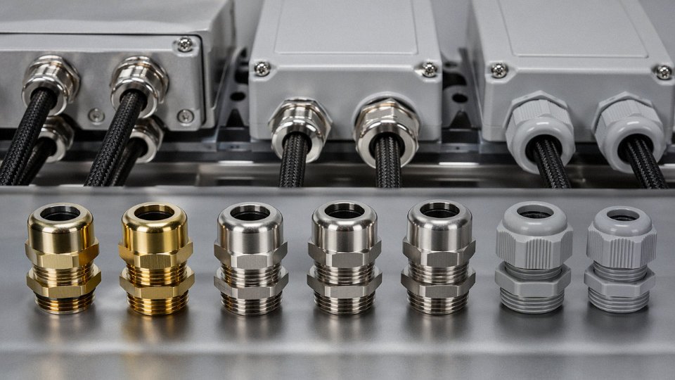
Standard brass cable glands are fine for indoor dry environments. Put them on an exposed coastal installation or anywhere near chlorinated water treatment, fertilizer storage, or acid fumes, and you’re looking at dezincification and seal failure within 3–5 years — sometimes faster in splash zones. The correct default for any exposed outdoor armored cable termination is 316L stainless steel with EPDM seal rings. EPDM handles UV, ozone, and temperature cycling far better than the NBR rings supplied with cheaper glands. In chemical plant environments where EPDM may not resist specific solvents, PTFE-encapsulated or Viton seals are worth the premium. Nylon glands have their place for light-duty, non-armored applications, but they provide no real armor clamping force and should never be specified for SWA or DSTA cables in exposed runs.
Armor Clamping and Earth Continuity
The armor cone and locknut arrangement inside a correctly specified armored gland exists for two reasons: mechanical retention and earth path. A gland that’s undertorqued — even by a half-turn — can produce earth impedance 10 to 50 times higher than a properly installed one, which matters critically for fault clearance times on systems relying on armor as the circuit protective conductor. Armor wires must be dressed evenly over the cone; bunched or crossed wires create point contact rather than distributed clamping. On DSTA cables especially, the tape layers need to be folded back cleanly, not cut flush, before the gland is assembled. It’s worth checking continuity across each gland with a low-resistance ohmmeter during commissioning — target values below 0.1 Ω are achievable and expected.
A poorly torqued armored cable gland can have 10–50× higher earth impedance than a correctly installed one.True
Armor clamping depends on even, distributed contact pressure between the armor wires or tapes and the gland cone. Insufficient torque reduces contact area dramatically, raising resistance in proportion. This is well-documented in IEC 62444 testing methodology and confirmed by field measurements on installation sites.
IP Rating: Match the Gland to the Actual Environment
Outdoor exposed terminations need a minimum IP66 gland — that’s the baseline, not a conservative choice. Locations subject to flooding, wash-down, or below-grade junction boxes in wet soil require IP68 glands rated for at minimum 1 m immersion per IEC 60529; installations near water intake structures or in areas with seasonal inundation should be specified to 3 m. The IP rating of the gland must match or exceed the IP rating of the enclosure it’s mounted on, otherwise the enclosure rating is meaningless.
Shrink Termination Kits for Medium-Voltage Cables
On medium-voltage armored cables terminated in exposed outdoor switchgear or junction boxes, the cable screen cutback is a partial discharge initiation site if left unmanaged. Heat-shrink or cold-shrink stress relief and weatherproofing kits aren’t optional extras — they’re mandatory for any MV termination exposed to moisture, temperature cycling, or contamination. Cold-shrink kits are generally easier to apply in confined outdoor locations where a gas torch is impractical or prohibited. The kit must be rated for the cable’s voltage class and compatible with the sheath material; XLPE-insulated cables have specific kit requirements distinct from EPR-insulated cables.
Condensation Control Inside Enclosures
Even a perfectly sealed gland won’t prevent condensation inside an enclosure that breathes through repeated heating and cooling cycles. Installing a breather drain plug at the lowest point of the enclosure, or including a silica gel desiccant pack and replacing it on a defined maintenance schedule (typically every 12–18 months depending on climate), adds a meaningful layer of protection for terminals and connections. In humid tropical environments or anywhere with large day-night temperature swings, this step is particularly important and frequently skipped.
Jinda’s technical team provides a gland pairing guide matched to each armored cable product series, specifying gland entry size, seal ring material, and recommended torque values. Bulk project orders include a pre-termination inspection checklist covering sheath preparation length, armor dressing procedure, seal ring condition checks, and post-installation continuity verification — documentation that simplifies both site QA and third-party inspection sign-off.
Frequently Asked Questions About Exposed Armored Cable
Can armored cable be left exposed outdoors permanently without conduit?
Yes, in most IEC-jurisdiction projects this is entirely standard practice. The critical qualifier is the outer sheath: UV-stabilized HDPE or UV-grade PVC are the minimum you should specify for any run that sees direct sunlight year-round. An unprotected standard PVC sheath can lose 30–40% of its tensile strength within two to three years of outdoor sun exposure — that’s not a long-term installation, that’s a maintenance liability waiting to happen. UV-stabilized HDPE sheaths, by contrast, are routinely rated for 20–25 years of outdoor service. No conduit is required by IEC 60364 for correctly specified, properly supported outdoor exposed runs, though you should always verify local amendments — certain Gulf states and some Southeast Asian jurisdictions have added conduit requirements in their national annexes.
Does steel wire armor provide sufficient rodent protection in warehouses or agricultural buildings?
SWA provides real deterrence. A rat or marten will typically move on to an easier target once it hits the steel wires. But “deterrence” is not “proof.” Determined rodents — and in high-pressure environments like grain stores or poultry farms, they are determined — can work their way through the outer sheath and gnaw around individual wires over time. The armor doesn’t stop them from reaching the insulation if they’re persistent enough. In genuinely high-rodent-risk installations, physical separation (cable routed in steel conduit or enclosed trunking at low levels) is the more defensible engineering choice, not just because of the cable but because of what a fault in that environment means for fire risk.
Can I use SWA armored cable for surface wiring in a domestic house?
Technically, nothing prevents it. In practice, SWA is overkill for most residential surface runs — the cable is heavier, the glands and termination fittings cost more, and the installation labor goes up. In the UK market, STA armored cable or twin-and-earth clipped direct is far more common for domestic surface wiring. For North American projects, NEC-compliant MC cable (metal-clad) is the recognized equivalent — same concept, different construction standard. If someone is quoting SWA for a domestic rewire, it’s worth asking why.
Standard SWA armored cable requires no conduit for outdoor exposed installation under IEC 60364 when fitted with a UV-stabilized outer sheath.True
IEC 60364-5-52 permits direct surface mounting of armored cables outdoors provided the cable construction is appropriate for the environmental conditions, including UV resistance. Conduit is not mandated by the base standard, though national annexes may add requirements.
Is armored cable self-supporting for aerial runs between buildings?
No. This comes up more than it should. The armor is there to resist radial crush and abrasion — it carries essentially no design tensile load. Span a standard SWA cable unsupported over anything more than roughly 3–5 m and you’re putting stress on the conductors and insulation that the cable simply isn’t rated to handle. For inter-building spans, a separate catenary messenger wire lashed to the cable, or pre-assembled aerial bundled cable (ABC) with an integral messenger, is the correct solution. The messenger takes the load; the cable just hangs.
What is the maximum ambient temperature for exposed armored cable near boilers or furnaces?
PVC-insulated armored cable tops out at 70°C continuous ambient. XLPE-insulated armored cable pushes that to 90°C. Above 90°C you’re outside the territory of standard polymeric cables entirely — that’s where silicon rubber insulated armored cable or MICC (mineral insulated copper-clad) cable becomes necessary. MICC can handle continuous temperatures well above 250°C depending on the termination type. Getting this wrong isn’t just a compliance issue; PVC insulation that’s been cooked past its rating gets brittle, cracks under vibration, and can fail to ground at the worst possible moment.
How do I prevent galvanic corrosion between steel armor and aluminum cable trays in coastal installations?
Steel-on-aluminum in a salt-laden atmosphere is a textbook galvanic couple. The fix is straightforward but often skipped in the field: use plastic-coated cable trays, or fit insulating liner strips (neoprene or HDPE saddle strips work well) anywhere the cable makes metallic contact with the tray. Apply anti-corrosion paste — a zinc-rich or petrolatum-based compound — at all clamp points and gland entries. Inspect annually in the first two years if the site is within a few kilometers of the coast; you’ll see staining before you see structural failure, which gives you time to intervene.
Does Jinda supply armored cables pre-cut to length with factory-fitted termination kits?
Yes. For large project orders, Jinda’s export team can arrange cut-to-length drums, custom reel quantities, and factory termination kits sized to the specified gland and cable OD. This matters on offshore or remote-site projects where having the wrong drum length means either a field joint or wasted cable — neither of which is free. Contact Jinda’s export sales team with your cable schedule and project timeline for a project-specific quotation; lead times and minimum order quantities vary by cable type and sheath specification.
Specifying and Procuring Exposed Armored Cable for International Projects: Jinda’s Supply Capabilities
For an EPC contractor running a cable schedule across three voltage levels and two continents, the supplier question isn’t just about price per meter. It’s about whether one source can cover the full scope without introducing a secondary vendor mid-project — because that’s where schedule slippage actually happens.
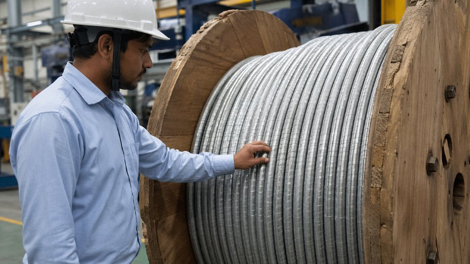
Shandong Jinda Special Cable Group, established in 1987, operates five production bases across China with a combined manufacturing footprint of roughly 470,000 m². That scale matters operationally. Low-voltage SWA power cables, medium-voltage XLPE armored feeders, armored fire-resistant LSZH cables, and multi-pair armored instrumentation cables can be produced simultaneously across dedicated lines without the outsourcing that smaller cable houses quietly rely on when order books fill up. In practice, outsourced drums are one of the harder risks to detect during factory audits — and one of the more common sources of construction inconsistency on large exposed-cable projects.
Product Range Covering the Full Scope of Exposed Installations
For exposed runs specifically, Jinda’s catalog spans conductor cross-sections from 1.5 mm² through 630 mm² in low-voltage SWA, STA, and AWA armored constructions, with voltage ratings up to 0.6/1 kV. Medium-voltage XLPE-insulated armored cables extend to 35 kV, which covers the majority of industrial substation feeder applications where surface-mounted exposed runs in cable trays or along structural steelwork are the norm. Armored fire-resistant and LSZH variants — relevant wherever exposed cables pass through occupied areas, escape routes, or offshore accommodation modules — are manufactured in-house rather than assembled from bought-in cores.
Armored instrumentation and control cables, multicore constructions with individual and overall shields, are a separate capability that EPC procurement teams sometimes overlook until the instrument cable schedule lands late. Having those on the same order and the same documentation package simplifies project approval considerably.
Standards Coverage and Third-Party Test Documentation
Jinda armored cables are manufactured and type-tested to IEC 60502, BS 5467, AS/NZS 1429, and GB/T 12706, with full third-party test reports available for project approval submissions.True
These are the primary international standards governing power cable construction and testing. Type-test reports to these standards are standard documentation for project approval on international EPC contracts.
That standards breadth matters because project approval submissions — particularly for projects in the Middle East, Southeast Asia, Australia, and Sub-Saharan Africa — routinely require certificates referencing specific standards rather than accepting a generic “meets international standards” declaration. Having the test reports on file, rather than needing to commission fresh testing at project start, typically saves three to six weeks in the approval queue.
Quality Assurance Infrastructure
Every drum shipped goes through in-house high-voltage testing, conductor resistance verification, and mechanical property checks covering armor crush resistance, sheath tensile strength, and elongation. Fire performance test chambers are on-site for LSZH and fire-resistant constructions. That’s not unusual for a plant of this size, but the relevant point for procurement managers is that third-party witnessed testing can be arranged at the factory during production — which some project specifications require and which isn’t always feasible with smaller suppliers.
Logistics, Lead Times, and Export Documentation
Standard armored cable products ship within 10–15 business days from confirmed order. Custom constructions — non-standard conductor configurations, unusual sheath compounds, project-specific drum lengths — typically run 30–60 days depending on material lead times and production scheduling at the time of order. Jinda’s export documentation team handles letters of credit, bills of lading, certificates of origin, and the country-specific compliance paperwork for more than 50 export markets. That’s the kind of institutional experience that prevents a documentation error from holding a shipment at port.
Technical Partnership for EPC and Bulk Procurement Accounts
Dedicated project engineers are assigned to EPC and bulk procurement accounts. The practical scope covers cable schedule review, ampacity calculations cross-referenced against actual installation conditions, drum schedule optimization to minimize site offcuts, and technical advisory for exposed cable routing decisions on critical projects. It’s a more useful engagement than a standard sales relationship, particularly on projects where the cable specification is still being finalized during procurement.
To initiate a technical proposal and competitive quotation — typically returned within 48 hours — submit your cable schedule, installation environment description, and the applicable project standards to Jinda’s export team directly.