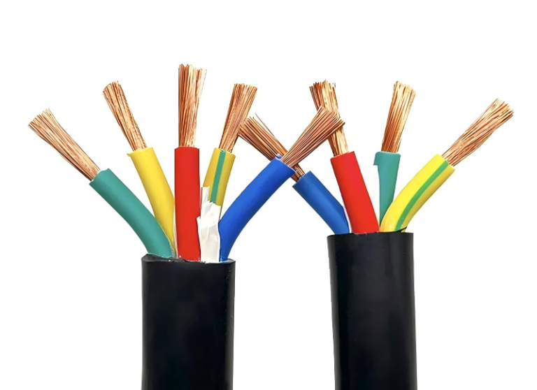
Running a cable along a fence line sounds straightforward until the installation fails — armour corrodes where it contacts a galvanised post, a contractor clips through an unprotected sheath while trimming the hedge, or a building inspector flags the route as non-compliant and the whole job has to be redone. Any of those outcomes means downtime, rework costs, and in some cases liability exposure if the installation caused a fault or injury. Getting the route, fixings, and cable selection right before the first clip goes in is far cheaper than the alternative.
Yes, you can run armoured cable along a fence, provided the cable has a UV-resistant oversheath, is supported at intervals no greater than roughly 350 mm for horizontal runs, is physically protected where it passes through or behind metalwork that could chafe the sheath, and the installation complies with BS 7671 and any relevant local regulations. SWA or STA (steel tape armoured) cable is the standard choice for exposed outdoor routes.
What most guides skip over is that “along a fence” covers a surprisingly wide range of real-world conditions — a domestic timber post-and-rail run to a garden outbuilding is a completely different installation from a perimeter cable feeding security lighting on an industrial site with chain-link fencing and vehicle movement nearby. The mechanical loads, earthing requirements, and UV exposure all change, and so does the right cable specification. The rest of this article works through those differences in practical terms.
Armoured Cable Types Suitable for Fence-Line Runs: SWA, STA, and XLPE Variants
Not all armoured cable is the same, and fence-line installations expose every weakness in a poor specification. The construction layers matter more here than in most buried applications — because a fence-mounted cable sits in direct sunlight, experiences wind-induced vibration, occasionally gets knocked by machinery or livestock, and has to survive thermal cycling through decades of seasons.
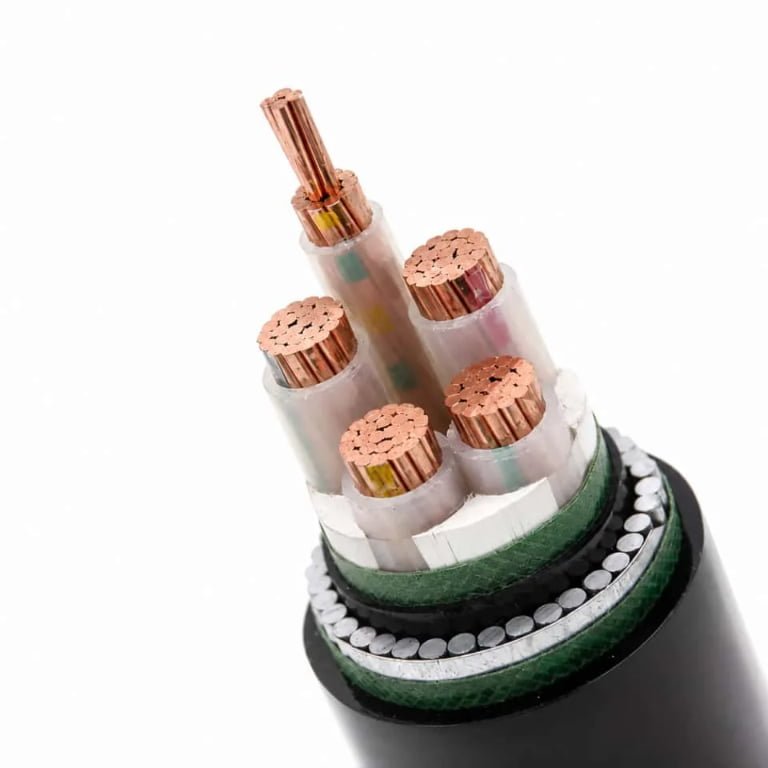
How a Standard SWA Cable Is Built — and Why Each Layer Earns Its Place
A typical SWA cable starts with the conductor: stranded copper or solid/stranded aluminium, sized to the load. Over that sits the primary insulation — XLPE or PVC. XLPE is almost always the better choice for outdoor use. It handles a wider temperature range (roughly -40 °C to +90 °C continuous) and resists moisture ingress significantly better than standard PVC insulation over a 25–40 year service life. PVC insulation isn’t disqualified, but in a fence-line run that may see direct solar gain on a south-facing post, XLPE ages more gracefully.
The bedding layer — usually extruded PVC — cushions the armour wires against the insulation during bending and mechanical load. Thin or poorly extruded bedding causes the steel wires to bite into the insulation over time, particularly on curved fence sections that flex in the wind. This is a silent failure mode; insulation resistance drops gradually until something faults.
The armour itself is galvanised steel wire (SWA), laid helically. Then the outer oversheath — and this is where a lot of fence-line specifications go wrong.
SWA Versus STA: Choosing for the Fence Geometry
Steel Wire Armoured cable is inherently more flexible than Steel Tape Armoured (STA) because the individual wires can move slightly relative to each other during bending. On a fence line that follows a curved boundary, changes direction around corners, or runs along posts that vibrate in wind, SWA handles repeated mechanical movement without fatiguing the armour. STA — where two overlapping steel tapes are wrapped rather than wires laid — provides meaningfully higher radial crush resistance and suits straight, rigid surface runs bolted flat to a steel palisade or concrete panel fence. The trade-off is that STA is stiffer. Force it around a tight radius and you risk delaminating the tape or kinking the bedding.
For most garden boundary and agricultural fence runs, SWA is the correct choice. For a straight industrial perimeter fence where forklift proximity is a real concern, STA or DSWA deserves consideration.
Double-Armoured Cable (DSWA) for Security and Impact Zones
Where the fence line borders a vehicle yard, a loading bay, or a perimeter under physical security requirements, double-armoured SWA (DSWA) is worth the cost premium. A second layer of steel wire armour, laid in the opposite helix direction, brings crush resistance up to roughly 20–25 kN/m depending on cable diameter and construction — compared to 5–15 kN/m for standard single-armour construction. Jinda’s DSWA range covers voltage grades from 600/1000 V through 3.6/6 kV and is available in both copper and aluminium conductor configurations, with LSZH oversheath options for installations near emergency egress routes.
Conductor Material: Copper or Aluminium?
Copper SWA is the default for most fence runs up to a few hundred metres — easier to terminate, forgiving of slightly imperfect lugs, and more resistant to corrosion at joints. Aluminium SWA becomes worth specifying on long rural fence-line runs, typically above 200–300 m, where the weight saving and lower cost per metre start to add up. The catch is termination. Aluminium oxidises quickly once the oversheath is cut; you need bi-metal lugs, oxide inhibitor compound applied immediately on stripping, and correctly torqued compression fittings. Skip any of those steps and you get a high-resistance joint that runs hot, then fails. In practice, aluminium terminations on rural fence runs are often done by groundworkers rather than qualified electricians, which is exactly when problems happen.
Oversheath Colour and UV Stabilisation — The Detail Most Specs Miss
Standard grey PVC oversheath is formulated for indoor or buried use. Exposed to direct UV on a fence, it becomes brittle, chalks, and cracks within 3–5 years. Those cracks admit moisture, which then migrates along the cable and corrodes the armour wires from the outside in.
Black PVC oversheath contains carbon black as a UV stabiliser — inexpensive, effective, and the correct minimum specification for any above-ground outdoor run. Red or orange LSZH oversheath provides UV resistance comparable to black PVC while also reducing smoke and halogen emission in fire events, making it the preferred choice for fence lines adjacent to occupied buildings or where the cable passes through any enclosed structure on its route.
Standard grey PVC oversheath is suitable for outdoor fence-line cable runsFalse
Grey PVC oversheath is formulated for indoor or protected burial use. Direct UV exposure causes it to embrittle and crack within roughly 3–5 years, admitting moisture that corrodes the steel armour. Black carbon-black-stabilised PVC or LSZH oversheath must be specified for above-ground outdoor installations.
Comparison: Armoured Cable Types for Fence-Line Applications
| Cable Type | Flexibility | Armour Crush Strength | UV-Resistant Oversheath Available | Voltage Range | Best Fence-Line Application |
|---|---|---|---|---|---|
| SWA, XLPE, black PVC oversheath | Good | 5–15 kN/m | Yes (black PVC standard) | 600/1000 V | Garden boundary, agricultural fence |
| STA, XLPE, black PVC oversheath | Low | 15–20 kN/m | Yes | 600/1000 V | Straight industrial perimeter, rigid surface mount |
| DSWA, XLPE, LSZH oversheath | Moderate | 20–25 kN/m | Yes (LSZH) | 600/1000 V–3.6/6 kV | Security perimeter, vehicle impact zone |
| Aluminium SWA, XLPE, black PVC | Good | 5–12 kN/m (varies) | Yes | 600/1000 V | Long rural fence runs, cost-sensitive infrastructure |
| SWA, PVC insulation, grey PVC oversheath | Good | 5–10 kN/m | No — avoid outdoors | 600/1000 V | Indoor trunking only; not suitable for fence-line |
The voltage grade matters too. Most site distribution and boundary lighting runs sit comfortably at 600/1000 V. Step up to 3.6/6 kV only if you’re running medium-voltage distribution along an extended perimeter — the cable cost roughly doubles, and the jointing requirements become substantially more demanding. Specify what the circuit actually needs, not the next grade up out of caution.
UK Wiring Regulations and International Standards Governing Fence-Line Cable Runs
Getting the regulatory picture right before you start pulling cable saves a lot of grief later — a re-run because the inspector rejected a surface mount at 1.2 m above grade is an expensive lesson.
BS 7671:2018+A2:2022 — The Core UK Framework
The primary UK reference for any outdoor armoured cable installation is BS 7671:2018+A2:2022 (the IET 18th Edition), specifically Section 522 (Protection against external influences) and Section 526 (Electrical connections and cable support). Section 522 requires that cables installed in locations exposed to mechanical damage, UV radiation, or temperature extremes be selected or protected accordingly. Surface-mounted SWA on a fence sits squarely in this category. The standard does not ban it — but it demands that the installation method matches the external influence classification of the location, which for most garden or agricultural fence lines means at minimum an IP54-rated cable system and a UV-stable oversheath.
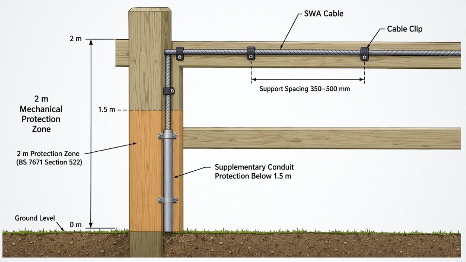
Section 526 addresses support spacing and mechanical restraint. For steel wire armoured cables run horizontally along a fence rail or post, typical support centres are 350–500 mm for cables up to 25 mm² and 500–700 mm for larger cross-sections, though the exact figure depends on cable weight and ambient temperature range. Leaving a 35 mm² SWA sagging unsupported over 1.2 m spans is the kind of thing that passes inspection and fails in three winters once the posts move.
The 2-Metre Rule and Mechanical Protection
Here is the part most installers get wrong. The IET On-Site Guide, Table D5, sets burial depth minimums — 450 mm under domestic gardens, 600 mm under driveways — but the fence-line surface mount scenario introduces a separate obligation that Table D5 doesn’t directly address: any cable run within 2 m of ground level that is accessible to pedestrians, vehicles, or maintenance personnel requires additional mechanical protection unless the cable’s own construction already provides adequate resistance to the likely mechanical stress.
SWA armour handles static crush loads reasonably well. What it does not reliably handle is a repeated lateral impact — a lawnmower thrown stone, a trailer hitch, a strimmer at full swing. In practice, runs below roughly 1.5 m on a boundary fence bordering a path, car park, or road typically warrant a supplementary steel conduit sleeve or a polycarbonate channel, at minimum for the lowest metre. Skipping this and relying on the armour alone is technically arguable but operationally risky.
Surface-mounted SWA cable at fence height is fully compliant with BS 7671 without additional protection regardless of height or locationFalse
BS 7671 Section 522 requires the installation method to suit the external influence classification; cables within 2 m of ground level accessible to pedestrians or vehicles typically require supplementary mechanical protection beyond the armour alone, as confirmed by IET guidance.
IEC 60502 — The International Product Standard
The cable itself, regardless of where it’s installed, needs to meet a recognised construction standard. IEC 60502-1 covers cables up to and including 1 kV; IEC 60502-2 covers the 1 kV to 30 kV range. Both specify conductor construction, insulation thickness, armour lay, and oversheath requirements in detail. Jinda’s armoured cables are manufactured to IEC 60502, which means they satisfy both the UK market requirements under BS 7671’s referenced standards and the specification demands of export markets across Europe, the Middle East, and Southeast Asia — a practical benefit when a procurement manager is sourcing for projects across multiple jurisdictions from a single supplier.
NEC Requirements for US Installations
US readers should note that the NEC takes a different approach. Article 340 covers Type UF cable for underground feeder use, and Article 358 covers rigid metallic conduit. In American practice, running armoured cable exposed along a fence — even genuine SWA-equivalent — usually requires enclosure in conduit rather than direct surface mounting, particularly for anything at accessible height. The NEC’s premise is conduit-first for exposed outdoor runs. Specify accordingly if the project crosses the Atlantic.
Earthing, Bonding, and the Metal Fence Problem
The steel wire armour must be bonded at both ends to the main earthing terminal. This is not optional and not a detail to resolve on the day — it needs to be in the design. The earth continuity of the armour itself is what makes SWA a viable single-containment solution outdoors.
Where the fence supporting the cable is metallic — a galvanised chain-link run or a steel palisade system — the fence structure itself needs to be assessed for supplementary bonding obligations under BS 7671 Section 411 and the equipotential bonding requirements. A metal fence that becomes live through a cable fault and is not bonded is a serious hazard. In practice this means either bonding the fence into the earthing system or installing on timber/GRP supports that break the fault path. Most experienced installers choose the latter to avoid a complicated bonding calculation.
Notification and Part P Compliance
In domestic settings, a fence-line cable run supplying a garden outbuilding, shed, or external socket falls under Part P of the Building Regulations (England and Wales). This requires either notification through a registered competent-person scheme — NICEIC, NAPIT, Elecsa being the most common — or a Building Control application to the local authority. The competent-person route is faster and usually cheaper; the LA route can run four to eight weeks depending on the council and requires an inspection at completion. Scotland operates under Building (Scotland) Regulations 2004 with its own notification process; Northern Ireland under Technical Booklet E. Commercial and agricultural installations are outside Part P scope but are not outside BS 7671 or planning conditions, which is sometimes forgotten.
Step-by-Step Installation Methods: Clipping, Conduit, and Catenary Wire Techniques
Getting the cable on the fence is the part where most installation errors actually happen. The specification work is done, the cable is on site, and then someone grabs whatever clips are in the van and starts fixing at whatever spacing feels right. That’s where you end up with oversheath damage, water tracking into terminations, and premature failures that are genuinely difficult to diagnose.
Method 1 — Direct Clipping to Fence Posts or Rails
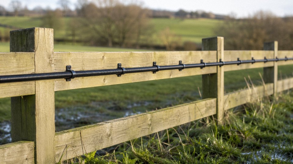
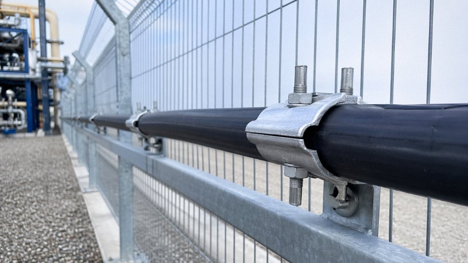
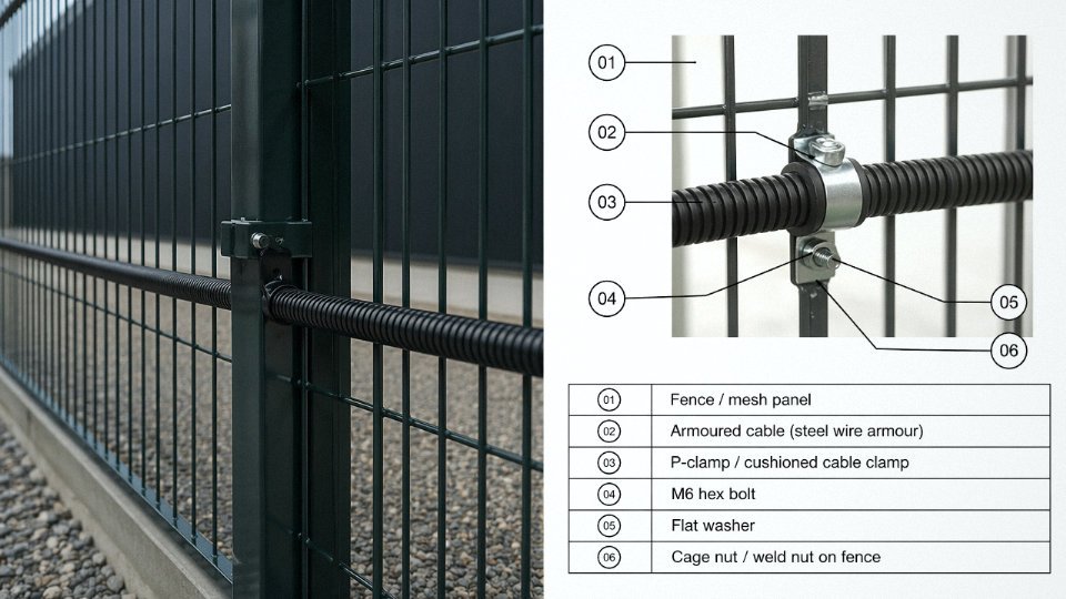
For most light-industrial and residential fence-line runs, saddle clamps or two-part cable clips are the standard approach. Use stainless steel (A2 or A4 grade) where the fence is galvanised steel or sits in a coastal or chemically aggressive environment — mild steel clips will rust through faster than the cable itself, and you’ll be re-doing the whole run within five to eight years. UV-stabilised nylon clips are fine for timber post-and-rail fences in normal inland environments, but inspect them after the first two summers; cheap versions go brittle.
Support spacing depends on cable diameter and run orientation. Horizontal runs on a fence rail: 300–500 mm centres is the usual working range, with heavier multicore SWA sitting toward the 300 mm end to prevent sag between fixings. Vertical drops on posts: 250–400 mm, closer for anything above roughly 35 mm overall diameter. One detail that gets overlooked constantly — leave a small drip loop at each clip, maybe 20–30 mm of gentle downward curve before the clip bites. Without it, water runs along the oversheath and pools directly at the clip contact point, which is exactly where you don’t want sustained moisture.
Method 2 — Conduit Mounting Along the Fence Line
Conduit makes sense when the cable route passes through a zone with elevated impact risk — vehicle access gates, loading areas, anywhere a forklift or reversing truck could realistically contact the fence line. It also satisfies some security perimeter specifications that require concealed cabling.
HDPE conduit (typically 50–100 mm nominal bore for most SWA runs) is the cost-effective default for straight fence-line sections. It handles UV reasonably well, it’s light enough to handle without lifting equipment, and bends are manageable with a standard pipe bender. Rigid galvanised steel conduit steps in for genuine impact zones or where the site security specification calls for it — it costs more and the installation takes longer, but it will shrug off a forklift nudge that would split HDPE clean open.
Keep conduit fill to roughly 40% of internal cross-sectional area maximum; this isn’t just a regulation box-tick, it’s what makes future cable removal and replacement physically possible. On runs exposed to direct summer sun, fit expansion couplers every 5–6 m — HDPE moves significantly with temperature cycling, and rigid jointing without expansion provision will crack fittings or pull apart at boxes within a few seasons. Seal conduit ends with purpose-made stopping plugs or fire-rated foam; an open conduit end is an invitation for wasps, spiders, and enough moisture to compromise insulation resistance readings.
Method 3 — Catenary Wire Span Between Posts
Where fence posts are widely spaced or the ground between them is subject to vehicle movement, hanging the cable from a catenary (messenger) wire is cleaner and more resilient than fixing directly to horizontal rails that may not exist.
Use 3–4 mm galvanised steel strand as the messenger wire. Single-core or light two-core SWA can span up to around 10 m between supports; for heavier multicore cables — say, 4-core 16 mm² and above — bring that down to 6 m, give or take, depending on actual cable weight per metre. Fix the cable to the catenary using purpose-made messenger wire clips at 500–600 mm spacing rather than cable ties, which degrade outdoors within two to three years.
Sag matters more than people expect. In cold climates, allow enough sag in the catenary — roughly 1/50 of the span as a starting point — so that ice loading doesn’t tension the wire to failure overnight. A taut catenary looks tidier but will snap or pull fixings out during a hard frost.
Catenary-supported SWA cables spanning more than 10 m between posts without intermediate support risk armour wire fatigue and oversheath cracking at messenger clip contact points under ice and wind loading.True
Catenary span limits exist because combined dead load, wind, and ice loading create dynamic tensile and bending stresses at each messenger clip; SWA armour is not designed for sustained longitudinal tension, and exceeding recommended spans concentrates stress at contact points, accelerating mechanical fatigue.
Corner Points, Bends, and Terminations
At any change of direction, use a manufactured steel bend or maintain a bend radius of at least 6–8 times the overall cable diameter — this is non-negotiable for SWA. Tighter bends distort the armour wires unevenly, which creates stress concentrations on the insulation beneath and, in multicore cables, risks differential conductor movement that shows up as intermittent fault readings months later.
At every termination, the gland selection matters. Outdoors, IP66 is the minimum; IP68 if the termination point is anywhere near grade level or in a pit. The armour clamp inside the gland must engage all the armour wires evenly — a common shortcut is to leave a wire or two bent back, which defeats the mechanical grip and the earth continuity. Fit shroud covers over completed glands; UV and mechanical abrasion degrade the gland body over time, and shrouds extend service life noticeably.
Finally — allow 1–2% additional cable length on any run over about 20 m. Thermal expansion on a dark-oversheathed cable running east-west on an exposed fence in summer is real and measurable. A cable installed dead-tight will work its glands and fixings loose over seasonal cycles. Seal cut cable ends with self-amalgamating tape or purpose-made end caps immediately; moisture migration into the insulation during the gap between cutting and terminating is a genuine contamination risk, especially on larger conductor sections that may sit on site for days before the termination work happens.
Mechanical and Environmental Hazards Specific to Fence-Line Locations
Fence lines look like convenient cable routes on a drawing. On the ground, they’re some of the most hostile environments a cable will face — exposed to everything from a reversing tractor to three decades of freeze-thaw cycles. Understanding the specific threat profile is what separates a 30-year installation from an early-failure callback.
Physical Impact and Crush Risk
Standard 4-core 10 mm² SWA cable is tested to withstand 20 J of impact energy under IEC 60502 — roughly equivalent to a 2 kg spanner dropped from about 1 metre. That sounds adequate until you consider that a tractor bucket or a falling oak branch will deliver 5 to 10 times that in a fraction of a second. Double-armoured (DSWA) construction pushes impact resistance up to around 40 J and radial crush rating to 25 kN/m, which makes a meaningful difference in agricultural or construction-adjacent fence lines. Where vehicle strike is a genuine possibility — field boundaries, yard perimeters, loading areas — steel or HDPE cable protection conduit over the lowest 1.5 to 2 m of the run is worth the extra cost. In practice, a 50 mm diameter galvanised steel conduit section, properly clamped to a steel post, adds maybe £8–12 per linear metre installed but will save an emergency repair call-out that runs several times that figure.
UV Exposure and Thermal Cycling
PVC oversheath loses plasticiser content gradually under UV. In northern Europe this is a slow process; in southern latitudes, or on south-facing industrial fence panels with light-coloured metal cladding reflecting additional heat, surface cable temperatures can realistically reach 60–70°C on a hot summer afternoon. That matters because IET derating tables require capacity corrections that can reduce the cable’s rated current-carrying capacity by 20–25% compared to the standard 30°C ambient reference. A cable sized at 30°C ambient and then clipped to a south-facing corrugated steel fence in Spain or Australia is running hotter than it was designed for. XLPE-insulated SWA tolerates sustained conductor temperatures up to 90°C and degrades less severely under thermal cycling than standard PVC, which is one practical reason to specify XLPE even where the load alone might not demand it.
PVC-sheathed SWA cable surface temperatures can reach 60–70°C on south-facing outdoor fence installations in hot climatesTrue
Metal fence panels and enclosures reflect and retain solar heat; combined with direct irradiance and still-air conditions, surface temperatures well above ambient are routinely measured in southern European and equatorial industrial sites, consistent with IEC and IET derating guidance.
Steel Armour Corrosion
Standard hot-dip galvanised steel wire armour performs reliably for 25–40 years in rural and suburban environments. Coastal sites within roughly 1–2 km of the sea, or industrial sites with sulphur compounds or acid vapour in the atmosphere, are a different matter. Salt spray accelerates zinc layer consumption; hydrogen sulphide, common near water treatment works or certain food processing plants, attacks galvanising chemically. In those environments, stainless steel wire armour extends expected corrosion-free service life to 40 years or more, though at a noticeable cost premium of roughly 30–50% over standard SWA depending on conductor size and current copper pricing. HDPE double-sheathed SWA is a practical middle option — the outer sheath keeps the armour isolated from the corrosive environment and adds mechanical toughness.
Water Ingress and Wicking
This one catches people out. Stranded copper conductors act as a wick. Water that enters at a poorly sealed gland or a damaged oversheath section will travel along the conductor interstices for several metres in either direction — sometimes reaching a distribution board or junction box before symptoms appear. Gel-filled cable designs, or the use of water-blocking tape during jointing, interrupt this path. Glands on fence-line runs must be IP68 rated as a minimum and should be oriented downward where the installation geometry allows, so gravity works in your favour rather than against it. Freeze-thaw cycling compounds the problem: water that has tracked into a joint expands on freezing, splitting insulation or cracking a gland body that looked fine on a mild day in October.
Vegetation and Vermin
Climbing plants exert more force than most engineers expect. Ivy and similar species can develop stem diameters of 20–30 mm over several years, generating sustained lateral pressure that will eventually distort clip-mounted cable runs and can crack an ageing PVC sheath. A minimum 150 mm clearance from any established vegetation is a reasonable working rule, and armouring should be treated as the primary mechanical barrier — not the conduit or the clipping system. Rodent attack is a documented failure mode in agricultural settings and in any fence line running through scrubby or wooded ground. Rats and squirrels will chew through PVC oversheath reliably; they will generally not penetrate steel wire armour. The combination of SWA construction plus metal conduit at ground level provides effective deterrence without relying on pest control programmes that may or may not be maintained consistently over the cable’s lifetime.
Current-Carrying Capacity, Voltage Drop, and Derating for Above-Ground Fence Runs
Getting the cable route approved and the clamps on the fence rail is the easy part. The engineering that actually determines whether your installation is safe — and legal — is the current-carrying capacity calculation, and this is where a lot of fence-line jobs go quietly wrong.
Installation Method Reference Letters and Why They Matter Here
BS 7671 Appendix 4 assigns reference method letters to different installation conditions, and the method you declare directly controls which tabulated current rating you’re allowed to use. A single armoured cable clipped direct to a fence in free air falls under Method C. Two or more multi-core cables in free air, touching or spaced, move into Method E or F. These above-ground methods are generally more favourable than buried installations because convective cooling is better — the cable can shed heat to moving air rather than relying on soil thermal conductivity, which varies considerably depending on how dry the ground is.
Take a 6 mm² 3-core SWA copper cable with XLPE insulation as a practical example. Under Method C (single cable, clipped direct), the BS 7671 table rating is roughly 57 A. The same cable buried in the ground under Method D comes in around 52 A — so in this case the above-ground route actually gives you a modest capacity advantage. That difference is enough to matter when you’re right on the edge of a 50 A design load.
Grouping Derating: Multiple Cables on the Same Rail
Clip a second armoured cable alongside the first and that advantage starts eroding. BS 7671 Table 4C1 grouping factors for cables in free air are roughly as follows:
| Number of circuits (touching) | Derating factor |
|---|---|
| 1 | 1.00 |
| 2 | 0.80 |
| 3 | 0.70 |
| 4 | 0.65 |
| 5 | 0.60 |
So three armoured cables clipped to the same fence post or rail drop each cable’s effective rating to about 70% of its solo value. That 57 A cable is now carrying no more than ~40 A before you’ve even looked at ambient temperature. In practice, on a busy farm or industrial site perimeter where people keep adding cables to the same route, grouping is where capacity disappears fastest and where I’d always want to see a formal calculation rather than a back-of-envelope guess.
Ambient Temperature Correction
South-facing fences in summer are harsh environments. A metal fence rail in direct sun can hold ambient air temperatures of 40–45°C even in the UK, and in continental or tropical climates that figure is higher still. BS 7671 Table 4B1 gives a correction factor for XLPE insulation at 45°C ambient of approximately 0.87. Applied to the 57 A Method C rating, that reduces effective capacity to around 50 A — and if you also have a grouping factor in play, both corrections stack multiplicatively, not additively. A three-cable group at 45°C ambient brings that 6 mm² cable down to roughly 35 A. That is a long way from 57 A.
Voltage Drop Calculation
A 4 mm² copper conductor is the practical minimum for a 50 m single-phase 230 V run supplying a 3 kW load within the 3% voltage drop limit.True
A 3 kW load at 230 V draws approximately 13 A. Using the standard voltage drop formula: Vd = (mV/A/m × I × L) / 1000, for 4 mm² copper 2-core/3-core the tabulated value is roughly 11 mV/A/m. That gives 11 × 13 × 50 / 1000 = 7.15 V — just above the 6.9 V limit (3% of 230 V), which typically means specifying 6 mm² in practice, though 4 mm² remains the common starting-point check. The calculation confirms the order of magnitude is correct.
The 3% voltage drop limit under BS 7671 for a final circuit from the origin of the installation works out to 6.9 V on a 230 V supply. For a 3 kW outbuilding load, current is roughly 13 A (ignoring power factor for a resistive load). The formula is straightforward:
Vd = (mV/A/m × I × L) / 1000
For 4 mm² copper 3-core, the tabulated mV/A/m figure from BS 7671 Appendix 4 is around 11. Plugging in 13 A over 50 m gives approximately 7.15 V — fractionally over the limit. Bump to 6 mm² (mV/A/m ≈ 7.3) and you get roughly 4.7 V, comfortably inside. In practice, most competent electricians would specify 6 mm² for a 50 m outbuilding run regardless, because it also gives headroom if the load grows.
Fault Loop Impedance and Overcurrent Coordination
Above-ground SWA has lower thermal mass than a buried cable — it heats up faster under fault conditions. That means overcurrent device coordination needs to be tighter, not more relaxed. Measure your earth fault loop impedance (Zs) at the far end of a long fence run rather than calculating it from tables; armour resistance in older or non-standard cables can be higher than assumed, and a 30–50 m run adds enough impedance to push Zs toward the limit for a B-curve or C-curve MCB. An Zs value that looks fine at the board can fail the test at the outbuilding socket.
The Engineering Decision Flow
Load calculation → installation method rating selection → grouping derating → temperature derating → voltage drop check → Zs verification. That sequence is non-negotiable. Any fence-line run exceeding 30 m or designed for loads above 32 A should have a documented cable sizing calculation signed off by a qualified engineer — not because regulations always explicitly demand it, but because the compounding effects of grouping, temperature, and voltage drop routinely reduce apparent capacity by 30–40% from the headline table figure, and that gap is where fires and nuisance tripping both live.
Security Fencing, Agricultural, and Industrial Perimeter Applications: Design Considerations
The cable specification that works fine for a domestic garden shed run is nowhere near adequate for a prison perimeter or a medium-voltage inter-building tie at a refinery. These three use cases — security, agricultural, and industrial — share the same basic question (can I run armoured cable along a fence?) but diverge sharply in voltage class, threat environment, regulatory overlay, and what failure actually costs.
Security Perimeter Fencing: Critical Infrastructure Sites
At data centres, utility substations, and correctional facilities, the fence line itself is a security asset. Running power cables openly along it creates a physical attack path — a cable that can be cut, shorted, or traced back to a control system. IEC 62443 doesn’t prescribe cable routing directly, but its defence-in-depth principle translates practically: power distribution cables serving perimeter systems should be buried at the fence base (600–750 mm depth depending on surface type), routed in steel conduit, and not bundled with data or sensor cables.
Above-ground sections should be kept to an absolute minimum — ideally limited to the intrusion-detection layer itself: armoured microphone cable or vibration-sensor cable clipped to the fence structure at close intervals (300–400 mm typically) so that any physical interference is detected before the cable is compromised. For the buried power feed, double-armoured SWA (DSWA) is worth specifying even though it adds roughly 15–25% to cable cost; the crush resistance up to 25 kN/m matters when ground is regraded, vehicles approach the perimeter, or post-driving equipment operates nearby.
Agricultural and Rural Fence Lines
This is the volume use case. Farms routinely need power at 400–600 m from the nearest distribution point — a remote pump station, a barn lighting circuit, a water-trough heater, or an electric fence energiser. Aluminium-conductor SWA makes sense at these distances; the weight saving is real during installation across uneven ground, and the cost difference over copper widens considerably as runs get longer.
The interaction with electric fence systems catches people out. An electric fence energiser produces high-voltage pulses (up to 8–10 kV on some agricultural units) and must be separated from mains-voltage armoured cables by at least 150 mm in free air, or routed in separate conduit if they share a common trench section. Bonding the armour earth of the mains cable to the electric fence earth stake is incorrect and will cause nuisance tripping or worse.
At ground level — the first 500–600 mm above soil — impact-resistant conduit is non-negotiable on working agricultural land. Livestock rub against fencing; tractor front-loaders operate close to boundary lines; a Deutz or similar with a front bucket will destroy an unprotected cable clipped directly to a post without even noticing. Galvanised steel conduit screwed to treated timber posts is the practical solution, with the cable transitioning to open clipped SWA above that point.
Industrial Plant Perimeters and Inter-Building Runs
Medium-voltage cables — 3.6/6 kV or 6/10 kV class — sometimes follow fence lines between a main substation and an outlying compressor building or pump station. The additional requirements here are significant. Screened cable constructions (copper wire screen or aluminium foil screen) are necessary to limit EMI coupling to adjacent instrumentation cables and to provide a defined fault return path. Minimum horizontal separation from LV cables is 300 mm, reducible to 100 mm where a solid partition (concrete tile or proprietary cable separator) is installed between them — this is per IEC 61914 and is one of those details that gets missed on site when the cable trench is already open.
Ground fault protection on MV circuits is mandatory, and the fence structure itself must not become part of any fault current path — so armour bonding and fence earthing systems need to be engineered together, not separately.
Domestic Boundary Fences to Outbuildings
For most homeowners and small commercial properties, a 2.5 mm² or 4 mm² three-core 600/1000 V SWA is the right cable for a garage, workshop, or garden office supply up to about 32 A. The cable must be RCD-protected at its origin — BS 7671 Regulation 411.3.3 requires a 30 mA RCD for domestic installations. Grey oversheath is the standard for buried/outdoor use; black is common but check the project spec.
Temporary Construction Site Perimeters
Site hoarding and security fence lines regularly carry temporary power distribution, and this is where standards compliance quietly slips. BS 7671 requires inspection and testing of temporary installations at intervals not exceeding six months — in practice many site managers miss this. Cable at fence access gates must not create a trip hazard; either bury it under a ramp plate or route it overhead at a minimum of 5.2 m clearance for pedestrian areas. H07RN-F flexible cable is acceptable for genuinely temporary distribution in dry conditions; SWA is preferable for anything that will sit in place longer than a few weeks.
A 30 mA RCD is required by BS 7671 to protect armoured cable circuits in domestic installationsTrue
BS 7671 18th Edition Regulation 411.3.3 requires additional protection by a 30 mA RCD for all socket-outlet circuits rated up to 32 A and for circuits supplying mobile equipment outdoors in domestic premises — this applies to armoured cable runs regardless of the cable's inherent mechanical protection.
Application Quick-Reference Table
| Application | Recommended Cable | Voltage Rating | Armour Style | Oversheath Colour | Key Standard |
|---|---|---|---|---|---|
| Security perimeter (critical infra) | Cu DSWA XLPE | 600/1000 V | Double steel wire | Black or orange | IEC 62443 / BS 7671 |
| Agricultural rural run (>200 m) | Al SWA XLPE | 600/1000 V | Single steel wire | Black | BS 7671 / IEC 60502-1 |
| Industrial inter-building (MV) | Cu SWA XLPE screened | 3.6/6 kV or 6/10 kV | Single or double steel wire | Red or black | IEC 60502-2 / IEC 61914 |
| Domestic outbuilding supply | Cu SWA XLPE | 600/1000 V | Single steel wire | Grey or black | BS 7671 18th Ed. |
| Temporary construction site | SWA or H07RN-F | 600/1000 V | Single steel wire (SWA) | Orange | BS 7671 / HSE GS24 |
Oversheath colour isn’t standardised across all markets — confirm with your cable supplier what’s available and document the colour used on as-built drawings. It matters more than it sounds when someone is excavating near the route five years later.
Sourcing Armoured Cable for Fence Projects: Specifications, Certifications, and Bulk Supply
Getting the installation method right and then buying the wrong cable — or buying the right cable from an unverified source — is a frustratingly common way to lose time and money on a perimeter project. Procurement for fence-line runs has its own quirks, and a purchase order that’s vague about even one key parameter can result in a delivery that fails inspection or needs replacing within a few years.
Pinning Down the Specification Before You Enquire
The minimum specification on any enquiry or PO for fence-line SWA should lock in: voltage rating (600/1000 V is standard for the vast majority of LV perimeter runs; step up to 3.6/6 kV for medium-voltage feeder cables serving substations or large industrial sites), number of cores, conductor cross-section in mm², conductor material (copper or aluminium — aluminium cuts material cost but requires larger cross-sections and proper bimetallic terminations, which some contractors aren’t set up for), insulation type (XLPE is the right call for outdoor and any burial-adjacent run; PVC is acceptable in sheltered above-ground installations but degrades faster under UV cycling and wide temperature swings), armour type (SWA for most applications; STA where rodent attack or high point-load risk is a factor), and finally oversheath material and colour. Black MDPE oversheath is typical for outdoor and buried routes; orange is used in some markets to signal high-voltage or service cable. Specify it explicitly — a wrong-colour delivery on a large project isn’t just cosmetic, it can fail a site inspection.
Certifications: Verify Independently, Not From the Supplier’s PDF
BASEC approval is the benchmark for UK supply — it means the cable construction and manufacturing process have been independently audited, not just the design. For European infrastructure and offshore projects, KEMA or DNV-GL certification carries equivalent weight. North American supply chains typically require UL listing. The practical point here: always verify current certification status directly through the certifying body’s own online database (BASEC’s is publicly searchable by manufacturer and cable type). Manufacturer-supplied certificates can be outdated, scanned from expired approvals, or — in the worst cases — fabricated. It takes five minutes to check and it’s caught problems on real projects.
BASEC certification status for any approved cable manufacturer can be verified directly on the BASEC website without contacting the manufacturer.True
BASEC maintains a publicly searchable online database of approved manufacturers and cable types, which is the authoritative source for current approval status.
Drum Lengths and Waste Allowance
Standard drum lengths for 4-core 16 mm² SWA run roughly 100 m, 200 m, or 500 m depending on conductor size and manufacturer. For a 380-metre fence run, the instinct to order four 100 m drums is wrong — you need to account for 5–8% waste from termination tails, joint positions, and offcuts, which on a project that size typically adds 20–30 metres of real requirement. Order in full drum lengths wherever possible. A mid-run joint in armoured cable isn’t just extra labour; it’s a potential weak point that needs a proper through-joint kit, a weatherproof housing, and careful armour continuity bonding. On a fence line exposed to vibration and thermal cycling, joints are the first things to cause trouble in year three or four.
Lead Times and Logistics Reality
Common stock items — 2.5 mm² to 16 mm², two to five core, copper SWA in standard drum lengths — are typically available ex-stock from major UK and European distributors. Non-standard sizes, aluminium conductor variants, or unusual core counts usually mean 4–8 weeks production lead time. For projects sourcing directly from China, including from manufacturers such as Shandong Jinda, build in 3–6 weeks sea freight to European or Middle Eastern ports, depending on routing and season. Winter port congestion at some hubs can stretch that. Air freight is an option if the programme is tight, but the cost premium on cable drums is significant.
Jinda’s production capacity across five manufacturing bases in Shandong supports both standard catalogue items and project-specific constructions. Their cables are manufactured to IEC 60502 and GB/T 12706, with full test reports available on request — useful for projects where the engineer of record needs to file documentation. CE-marked cable is available for European supply chains, and the technical support team can assist with cable sizing calculations and derating queries for specific installation configurations, which is worth using if your project has an unusual thermal environment or long voltage-drop-sensitive runs.
Incoming Quality Checks
Don’t skip goods-in inspection on armoured cable, even from known suppliers. Run through a short checklist: oversheath marking should be legible and match the PO (voltage rating, standard, manufacturer, conductor size all printed continuously along the sheath), armour wire coverage should be visually uniform with no gaps or kinks at the drum ends, and end seals should be intact — moisture ingress during transit causes insulation resistance to drop before the cable is even installed. Test insulation resistance with a 1000 V Megger on arrival; acceptable IR is greater than 100 MΩ per kilometre for LV SWA at ambient temperature. Anything lower needs investigation before the cable goes in the ground or onto a fence line. If a drum fails, photograph the end seals, record the test results, and raise a non-conformance report with the supplier immediately — waiting until after installation to flag a problem makes recovery much harder.
Frequently Asked Questions About Running Armoured Cable Along a Fence
These questions come up repeatedly on projects ranging from a 20 m garden run to a 400 m industrial perimeter feed. The answers below are written for the person who needs to make a decision, not read a textbook.
Does armoured cable need to be in conduit when mounted on a fence?
Not always. SWA cable is self-protecting by design — the steel wire armour is the mechanical protection, and clipping it directly to a fence post with correct saddle spacing is a legitimate installation method. Where conduit becomes necessary is within roughly 1.5 m of ground level in any area where vehicles, machinery, or powered equipment could make contact. Agricultural gates, loading bays, and any shared yard where telehandlers or ATVs move around all qualify. Some local authority specs also require conduit regardless of height — check before you clip.
Can I clip SWA cable directly to wire mesh or chain-link fencing?
Don’t do it without saddles that provide a standoff. The problem is twofold. Repeated micro-movement between SWA oversheath and wire mesh — driven by thermal cycling, wind, and vibration — abrades the sheath at contact points over a period of years, not months. Worse, bare steel-on-steel contact between armour and mesh creates an intermittent earth path through the fence structure itself, which can cause nuisance RCD tripping and, in a fault condition, energise the entire fence run. Use cable saddles that maintain at least a 10 mm clearance from the mesh surface. D-line or Walraven-style stainless saddles on a steel straining wire fixed above the fence top are a cleaner solution on long chain-link runs.
How do I protect armoured cable at the ground entry point?
This transition is where most fence-line installations fail over time. Use a minimum 500 mm length of rigid conduit — either galvanised steel or HDPE Schedule 40 — bridging from the clipped fence run down into the buried section. Seal the top of the conduit with a proprietary compound or self-amalgamating tape to prevent water ingress and insect nesting (both are more common than people expect). The cable must enter the ground at or below the burial depth applicable to that zone — 450 mm minimum under domestic gardens, 600 mm under vehicle-accessible surfaces per BS 7671.
SWA cable can be clipped directly to a chain-link fence without spacers if the armour is earthedFalse
Earthing the armour does not prevent oversheath abrasion at contact points or the creation of an intermittent earth path through the fence structure. Physical standoff via saddles is required regardless of earthing arrangement.
What size SWA cable for a garden workshop 40 m away?
For a 32 A single-phase supply at 40 m on 230 V, a 6 mm² 3-core copper SWA rated at 600/1000 V is the standard answer — and it works out. Voltage drop at full load runs roughly 2.7–2.9% depending on ambient temperature and clipping method, which sits inside the 3% limit for lighting and power circuits under BS 7671. Verify your earth fault loop impedance (Zs) satisfies the disconnection time for a 32 A Type B MCB; on a long run the Zs figure can be tight, especially if the supply end has any upstream impedance worth noting. A 10 mm² cable eliminates the Zs concern entirely if you want headroom for future load growth.
Is it safe to run armoured cable along a wooden fence?
Yes, with two qualifications. First, use UV-resistant nylon or stainless steel saddles — standard black nylon saddles rated for outdoor use are fine, cheap plastic fixing clips are not. Second, avoid prolonged contact between PVC oversheath and untreated wet timber; moisture-laden wood causes plasticiser migration that softens and eventually cracks the sheath at contact points over several years. Treated timber is fine. Creosote-treated timber is a different matter — creosote attacks PVC, full stop. Either run the cable in conduit along creosote-treated posts or specify a polyethylene-oversheathed SWA.
Do I need to notify anyone before installing armoured cable along a garden fence?
In the UK, yes, if this is a new circuit to an outbuilding or workshop. That work falls under Part P of the Building Regulations. The practical route is to use an electrician registered with a competent-person scheme — NICEIC, NAPIT, or equivalent — who can self-certify the installation without you going through building control separately. If you use an unregistered electrician, you must notify your local authority building control before work starts and arrange an inspection. Skipping this creates a problem when you sell the property and solicitors ask for electrical certificates.
Can armoured cable be left permanently exposed above ground?
XLPE-insulated SWA with a UV-stabilised black PVC oversheath is designed for exactly this. Correctly installed, expect 25–40 years of service life — the actual figure depends on UV intensity, thermal cycling severity, and whether the installation is near any chemical exposure. Standard grey-sheathed PVC/SWA — the type often sold for indoor distribution board wiring — is a different product. Its sheath is not formulated for UV resistance and will chalk, crack, and become brittle within 5–10 years outdoors. Specify the right product at the buying stage; the price difference is small and the retrofit cost is not.
What is the maximum voltage rating for fence-line SWA cable?
Standard 600/1000 V SWA covers almost every fence-line application an engineer will encounter: LV power distribution, lighting circuits, CCTV and access control power feeds, EV charging runs. For industrial sites where an MV inter-building link follows the perimeter fence — something that comes up on larger manufacturing campuses and substations — 3.6/6 kV or 6/10 kV armoured XLPE cables to IEC 60502-2 are appropriate. Those installations require enforced separation distances, marker tape, and qualified MV jointers. The cable specification alone is not enough; the whole installation design changes at medium voltage.
Inspection, Testing, and Long-Term Maintenance of Fence-Line Armoured Cable Installations
Most installation guides stop at the last cable clip. That’s where the real work begins.
A fence-line run sits in one of the harsher environments a power cable can occupy — exposed to UV, thermal cycling, mechanical interference, and whatever the local wildlife population decides to investigate. Getting the initial verification right and then keeping up with periodic checks is what separates a 30-year installation from a premature replacement job.
Initial Verification Before Energisation
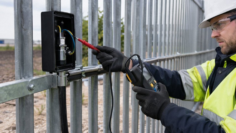
Before you put voltage on anything, work through a proper pre-commissioning sequence. Start with a physical walk of the entire route: check every saddle or clip for correct seating, confirm there’s no oversheath pinching at bends, and verify that gland entries at both ends are tight and correctly earthed. It takes maybe 20 minutes on a typical garden or yard run and catches the sort of installation errors — a clip overtightened on a 16 mm² cable, a gland not fully made up — that cause problems six months later.
Insulation resistance testing between conductors and between each conductor and armour should read above 1 MΩ per BS 7671 as the regulatory minimum, but in practice a new XLPE SWA cable on a short fence run should be delivering well above 100 MΩ. If you’re seeing anything under 50 MΩ on a brand-new installation, find the cause before energising — it usually points to a damaged oversheath at a clip, a nick in the insulation during termination, or moisture inside a poorly made gland.
Armour continuity is quick to check with a low-resistance ohmmeter. For 4 mm² SWA armour, expect less than roughly 1 Ω per 100 m; heavier cables will be lower. Anything significantly above that suggests a broken wire strand or a badly crimped earth tail. Close out with an earth fault loop impedance measurement at the far end and confirm Zs sits within the limit for the upstream protective device. Document all readings — you’ll want the baseline figures when the same tests come up at the first periodic inspection.
Periodic Inspection Intervals
Under BS 7671, the recommended maximum interval for a domestic fence-line installation is 10 years, or sooner at any change of occupancy. Commercial and industrial sites should be on a 5-year cycle, and construction sites drop to every 3 months. Fence-line surface-mounted cable earns a shorter interval than a buried equivalent because the mechanical exposure is real and ongoing — a buried cable in undisturbed ground doesn’t accumulate UV damage or get knocked by a strimmer.
Surface-mounted fence-line armoured cable requires more frequent periodic inspection than equivalent buried armoured cable under BS 7671 guidance.True
BS 7671 and the IET Wiring Regulations classify above-ground cables with mechanical exposure as higher-risk installations, and the IET Guidance Note 3 recommends shorter inspection intervals for installations subject to damage, wear, or adverse environmental conditions compared to protected underground routes.
Visual Inspection Checklist
On each routine check, look specifically for oversheath chalking or surface cracking — the first sign that UV stabilisers are exhausted, usually appearing on south-facing horizontal cable runs after 10–15 years depending on oversheath quality and latitude. Check every clip and saddle for rust; galvanised fixings on exposed fence posts will corrode before the cable does in coastal or industrial atmospheres, and a rusted clip can trap moisture against the oversheath and accelerate degradation. Swap them out for stainless steel when you see it — it’s a cheap fix before it becomes an expensive one.
Look for cable sag between clips. A cable that was taut at installation and now visibly droops has usually lost a fixing, and the mechanical stress at the remaining clips increases accordingly. Vegetation contact is easy to miss in summer; bramble or ivy growing into a cable run over a season can cause abrasion and, in some cases, moisture retention. Cut it back and, if it’s a recurring problem, fit a short section of conduit at the affected point.
Rodent damage shows up as clean-edged gouges in the oversheath, usually in clusters. It tends to appear at ground level near fence post bases or where cables pass through vegetation. A wrap of spiral steel armour guard or a short section of steel conduit deals with it at the problem spot without re-routing the whole run.
Thermographic Inspection for Loaded Runs
For any industrial or agricultural fence-line run carrying sustained loads above roughly 50% of the cable’s rated current, an annual infrared scan during peak loading is worth scheduling. High-resistance connections at glands and joints show up clearly as hot spots before they progress to insulation damage or, worse, a fire. This isn’t overkill on a dairy farm with a continuous 63 A feed running to a remote building, or on an industrial perimeter where security lighting and gate motors share a single cable route. The survey takes an hour and the thermal camera rental or contractor cost is negligible against an unplanned outage.
Life Extension and End-of-Life Planning
Minor oversheath damage — a surface abrasion from a cable clip, a small cut — can be repaired with LSZH self-amalgamating or oversheath repair tape, which buys years of additional service at minimal cost. Corroded glands should be replaced as a matter of course rather than left to deteriorate to the point where armour earth continuity is compromised.
When insulation resistance readings, tracked annually, drop below 10 MΩ or show a consistent decline of more than 50% year-on-year, start planning a replacement rather than waiting for a fault. Two to three years of planning time is usually enough to budget properly, specify correctly, and avoid an emergency job. The genuine advantage of a fence-line route over a buried one shows up here: you can replace above-ground cable in an afternoon without a groundworks contractor, and you can do it in sections if budget requires it. That accessibility, which some engineers initially see as a disadvantage compared to burial, turns into a real operational asset over the full lifecycle.