Cable TV signal degradation is one of those problems that looks like a dozen different problems before someone traces it back to the cable itself. Subscribers complain about pixelation, dropout on upper channels, or complete loss during wet weather — and the first instinct is to blame the headend, the amplifier, or the splitter. By the time the actual cause surfaces, a technician has made two truck rolls and the plant has eaten four to six hours of labor chasing a symptom. Wrong cable type, wrong impedance, or a spec mismatch at procurement quietly creates ongoing maintenance costs that compound across hundreds of drop installations.
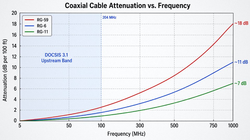
The cable type commonly used for cable TV is 75-ohm coaxial cable, with RG-6 being the standard for residential and commercial drops in modern CATV and HFC systems. RG-59 is older and still found in legacy installations, but its higher signal loss — roughly 7.5–8.5 dB per 100 feet at 100 MHz versus about 5.5–6.0 dB for RG-6 — makes it a poor choice for anything beyond short runs or low-frequency applications.
What most procurement specs and installation guides gloss over is that “coaxial cable” covers a surprisingly wide range of constructions, each optimized for a different position in the network — from the trunk lines spanning 500 to 2,000 meters between amplifiers in an HFC backbone, down to the final few meters of drop cable entering a subscriber’s wall plate. The differences matter operationally, and getting them confused at the purchasing stage or during a network upgrade creates problems that are genuinely difficult to diagnose after the fact.
Coaxial Cable Anatomy: How Each Layer Defines CATV Performance
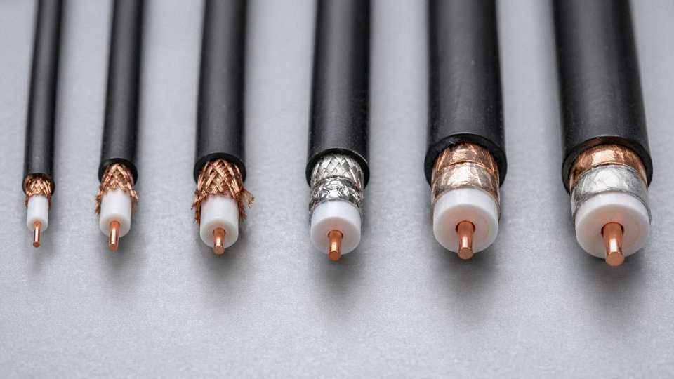
A coaxial cable looks simple from the outside. It isn’t. Every layer is doing a specific job, and specifying the wrong variant for a cable TV plant — even one layer wrong — will cost you in signal complaints, amplifier headroom, or premature field failures.
Inner Conductor: Copper Purity Matters More at High Frequencies
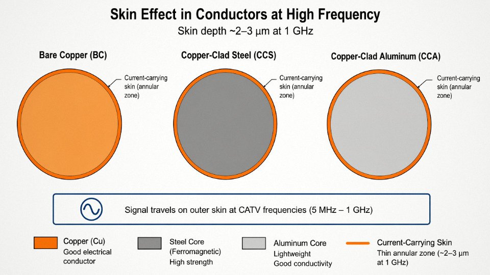
The three common inner conductor options are bare copper (BC), copper-clad steel (CCS), and copper-clad aluminum (CCA). Bare copper has the best conductivity, full stop. CCS trades some conductivity for tensile strength, which matters on aerial spans where the cable takes mechanical load. CCA is cheaper and lighter, but aluminum’s conductivity is roughly 61% that of copper, and that penalty shows up in insertion loss figures.
Here’s why conductor purity becomes increasingly critical above 50 MHz: skin effect. At CATV frequencies — typically 5 MHz to 1 GHz in a modern HFC system, with DOCSIS 3.1 pushing upstream channels toward 204 MHz — the signal doesn’t travel through the whole conductor cross-section. It travels on the outer skin, a layer that’s roughly 2–9 micrometers thick depending on frequency. For CCS, that surface layer is still copper, so at high frequencies it performs nearly as well as solid BC. For CCA, you get the copper skin benefit too, but the aluminum core creates problems if the end terminations aren’t made properly — aluminum oxidizes, and a corroded crimp connector under an outdoor F-connector is a fault you won’t find easily.
In practice, most headend and distribution coax for permanent CATV plant runs BC. CCS shows up where span length or wind loading is a concern.
Dielectric Insulation: The Foam Makes a Real Difference
Between the inner conductor and the shield sits the dielectric — the insulating layer that controls impedance and, critically, propagation velocity and attenuation. Solid polyethylene (PE) is the baseline. Foam PE, where the PE is expanded with nitrogen or a blowing agent to introduce air voids, lowers the dielectric constant from roughly 2.3 down toward 1.4–1.5. Lower dielectric constant means the signal travels faster and the cable loses less energy to dielectric heating.
The practical result: foam PE reduces attenuation by roughly 20–30% compared to solid PE at 1 GHz, depending on foam density and conductor geometry. Gas-injected foam PE (sometimes called “gas-foamed” or “super-foam”) pushes the air-void fraction even higher and is standard in RG-6 cables spec’d for broadband CATV. This is a large part of why RG-6 outperforms RG-59 — it’s not just the larger conductor, it’s the dielectric system.
Foam PE dielectric reduces coaxial cable attenuation by 20–30% compared to solid PE at 1 GHzTrue
Lowering the dielectric constant by introducing air voids reduces both dielectric losses and capacitance per unit length, directly improving the attenuation coefficient at high frequencies. This is well-established in coaxial transmission line theory and reflected in published cable spec sheets.
Shielding: Where CATV Systems Actually Fail in the Field
The shield does two things simultaneously: it’s the return path for the signal current, and it’s the barrier keeping outside interference out. These are not the same function and they don’t demand the same construction.
Single braid at 85% coverage was acceptable when CATV only carried analog channels below 300 MHz. Modern HFC plants with upstream channels in the 5–85 MHz (or now 5–204 MHz) band are extremely vulnerable to ingress — LTE signals from nearby cell towers, AM broadcast, impulse noise from motors and switching power supplies. All of that garbage enters through shield gaps and pollutes the upstream return path, which is what your DOCSIS data runs on.
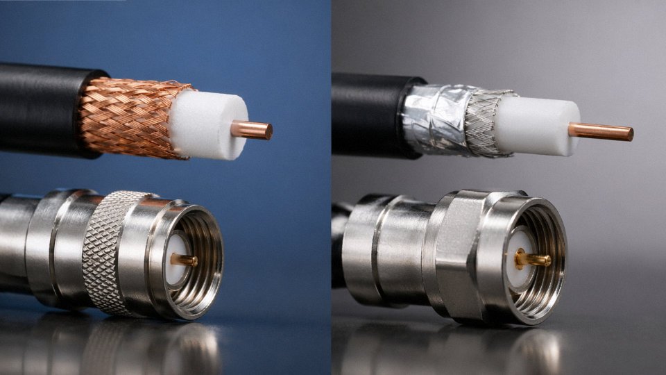
Quad-shield construction — foil plus braid, foil plus braid again — gives you 100% coverage on the foil layers and typically 95%+ braid coverage, for a combined shield effectiveness that’s genuinely difficult for ingress to penetrate. Foil-plus-braid (dual-shield) at 95% coverage is the minimum most operators should accept for indoor distribution. If you’re running cable in a dense multi-dwelling unit with a lot of consumer electronics nearby, quad-shield is worth the extra cost.
An operational warning: shield coverage percentage is meaningless if the braid isn’t properly terminated at connectors. A loose or poorly compressed F-connector on a quad-shield cable will perform worse than a correctly installed single-braid termination.
Outer Jacket: Matching the Environment, Not Just the Spec Sheet
PVC jackets are fine for indoor, conditioned-space runs. They’re flexible, inexpensive, and carry CMR (riser) or CMG (general) flame ratings depending on formulation. The problem with PVC outdoors is UV degradation — it gets brittle in three to seven years of direct sun exposure, depending on climate and plasticizer quality, and a cracked jacket on an aerial cable is an invitation for water ingress.
Outdoor aerial and underground CATV plant should use PE or HDPE jackets, which handle UV and temperature cycling far better. Temperature operating range matters: a PVC jacket rated to –20 °C will harden and crack during installation in a northern winter, even before it’s in service. LSZH (low-smoke zero-halogen) jackets show up in tunnel installations and plenum spaces where fire smoke toxicity is regulated. For direct-burial underground plant, flooded gel designs fill the cable’s internal air spaces with a water-blocking compound — without that gel, any jacket nick or connector seal failure becomes a moisture wicking path that corrodes the shield over months.
The 75-Ohm Standard: Not Arbitrary
CATV uses 75-ohm impedance universally. The reason traces back to transmission line physics: for a coaxial line with an air dielectric, roughly 77 ohms minimizes signal attenuation, and roughly 30 ohms maximizes power handling. The 75-ohm standard is a practical compromise weighted toward low loss, which is exactly what a passive distribution network needs.
The consequence of mixing impedances is a standing wave ratio (SWR) mismatch that reflects energy back toward the source. Connect a 50-ohm RF test instrument to a 75-ohm CATV system without an impedance pad and you’ll get reflections that look like ghosts on analog channels or elevated uncorrectable codeword errors on DOCSIS. It’s a mistake that’s easy to make in a lab setting and surprisingly common when technicians borrow RF test gear from a different application.
RG-59 vs. RG-6 vs. RG-11: Matching the Right Grade to the Right CATV Application
Picking the wrong cable grade doesn’t always fail immediately. That’s actually the problem. A system installed with RG-59 throughout a modern MDU might pass basic commissioning and then slowly degrade — intermittent pixelation, upstream noise complaints, a DOCSIS modem that keeps dropping — until a technician finally traces it back to cumulative attenuation loss that was baked in from day one. Getting the grade right at specification time costs nothing extra. Getting it wrong costs a truck roll, a wall opening, and an unhappy property manager.
RG-59: Understand What It Was Designed For
RG-59 uses a 20 AWG center conductor and a solid or stranded copper-clad steel core depending on the manufacturer and price point. At 100 MHz it loses somewhere in the range of 7.5–8.5 dB per 100 feet — that upper end depending on conductor quality and dielectric consistency. For analog baseband video over short runs, say under 40–50 feet, it was entirely adequate and was the standard residential drop cable through most of the 1980s and 1990s.
The honest answer today: RG-59 has almost no place in a new CATV installation. It’s still reasonable for short CCTV analog runs, composite video patching, or legacy baseband applications where the run is short and nobody is pushing signals above 500 MHz. Beyond that, its higher attenuation becomes a budget problem fast, and most modern compression tooling is sized for RG-6 anyway. Stocking RG-59 for CATV work is usually a sign a contractor is reusing old inventory, not making a deliberate engineering choice.
RG-6: The Working Standard
RG-6 is where nearly all residential and light commercial CATV work lands today, and for good reason. The 18 AWG center conductor paired with a foam polyethylene dielectric brings attenuation down to roughly 5.5–6.0 dB per 100 feet at 100 MHz — that range varying with dielectric density and shielding configuration. Tri-shield and quad-shield variants add an extra foil-braid layer (or two) that becomes meaningful in electrically noisy environments: apartment buildings near HVAC equipment, commercial ceilings with dense conduit runs, or any installation where upstream ingress noise is a recurring headache.
Premium RG-6 variants rated to 3 GHz are what make DOCSIS 3.1 and satellite IF distribution viable over the same plant infrastructure. That matters more than it used to. A contractor specifying RG-6 for a new build should confirm the frequency rating on the data sheet — not just the product name — because “RG-6” covers a wide range of actual performance depending on the manufacturer.
RG-11: When You Need the Reach
RG-11’s 14 AWG center conductor keeps attenuation in the range of 3.5 dB per 100 feet at 100 MHz, which is why it’s the standard choice for trunk drops, aerial spans over roughly 100 feet, underground feeder runs, and riser distribution in MDUs. The physics are straightforward — more copper, less resistance, less loss over distance.
The trade-offs are real though. RG-11 has a notably larger OD (typically around 0.405 inches versus RG-6’s 0.270 inches), a bend radius that punishes anyone trying to route it through tight conduit runs, and a per-foot cost that’s meaningfully higher. In practice, most professional installers use RG-11 from the tap to the building entry point — sometimes called the home run — and transition to RG-6 for interior distribution. That cascade approach manages the loss budget efficiently without paying RG-11 prices for every interior drop.
RG-6 and RG-11 use the same F-connector compression toolingFalse
RG-6 and RG-11 have different outer diameters and require different F-connector compression fittings and corresponding tooling dies. Using RG-6 connectors on RG-11 cable produces a poor mechanical fit, elevated return loss, and a path for moisture ingress — a common field error when crews mix cable grades on the same job.
Connector compatibility is where mixed-grade installations get into trouble more often than people expect. The F-connector dies in a compression tool are sized to the cable OD. An RG-6 compression fitting on RG-11 cable won’t seat properly, and the resulting poor connection creates return loss and upstream noise that’s genuinely difficult to isolate during testing. Mark your tool bags clearly if a job uses both grades.
Quick-Reference Grade Comparison
| Parameter | RG-59 | RG-6 | RG-11 |
|---|---|---|---|
| Center conductor | 20 AWG | 18 AWG | 14 AWG |
| Nominal OD | ~0.242 in | ~0.270 in | ~0.405 in |
| Attenuation @ 100 MHz | 7.5–8.5 dB/100 ft | 5.5–6.0 dB/100 ft | ~3.5 dB/100 ft |
| Attenuation @ 400 MHz | ~15–17 dB/100 ft | ~11–12 dB/100 ft | ~6–7 dB/100 ft |
| Attenuation @ 900 MHz | ~24–27 dB/100 ft | ~17–19 dB/100 ft | ~10–11 dB/100 ft |
| Max frequency (typical) | 1 GHz | 1–3 GHz (grade-dependent) | 1 GHz |
| Minimum bend radius | ~1.5 in | ~2 in | ~3.5 in |
| Typical installed cost | Lowest | Moderate | Higher (roughly 2–3× RG-6) |
| Primary CATV use | Legacy/short CCTV | Residential/commercial drop | Trunk, feeder, long spans |
Attenuation figures depend on cable construction quality, conductor material (solid copper vs. copper-clad steel), and dielectric formulation. Cost ranges reflect general market conditions and will vary by region, order volume, and shielding tier.
HFC Network Architecture: How Trunk, Feeder, and Drop Cables Work Together
Most residential installers only ever touch the drop — that last stretch of RG-6 from the tap on the telephone pole to the back of a set-top box. That’s fine for their job. But procurement managers and plant engineers need to understand the entire outside plant hierarchy, because specifying the wrong cable grade at any tier doesn’t just degrade one subscriber’s signal. It creates cascading loss problems that amplifiers can’t fully recover, and eventually you’re rolling trucks.
The HFC Model: Fiber Gets You Close, Coax Gets You Home
In a hybrid fiber-coaxial network, the headend transmits downstream signals over single-mode fiber to optical nodes distributed throughout a service area. From the node outward, the distribution is entirely coaxial. This split architecture is how MSOs — major cable operators serving urban grids, suburban sprawl, and everything in between — deliver broadband and video to hundreds of millions of subscribers worldwide. The fiber portion handles the long haul cleanly and cheaply. The coaxial portion handles the local density, the branching, the drops into buildings where pulling fiber to every unit would be prohibitively expensive.
Each tier of that coaxial plant is a different cable type, a different diameter, a different mechanical spec. They are not interchangeable.
Trunk Cable: The Backbone You Don’t See
Trunk cable is large-diameter hardline — typically the 0.500-inch or 0.750-inch series — with a solid aluminum outer conductor that doubles as the structural member. It’s rigid. You cannot coil it loosely or bend it around a corner the way you would RG-6. The aluminum sheath provides a genuine moisture barrier, which matters when the cable is buried for 20 years under a road.
Trunk spans run 500–2,000 meters between line amplifiers, depending on cable diameter, frequency plan, and the MSO’s cascade design. Larger diameter means lower attenuation per unit length, so amplifier spacing can stretch further — which reduces both capital cost and long-term maintenance burden on the amplifier plant. Municipal operators running high-frequency DOCSIS services push toward 0.750-inch trunk precisely for this reason.
Feeder Cable: Where the Signal Splits
Feeder (sometimes called distribution) cable branches off the trunk at bridger amplifiers and runs through neighborhoods to pedestal-mounted or strand-mounted taps. Typical sizes are 0.412-inch or 0.500-inch hardline, again with aluminum outer conductor. Signal at this stage has already been split from the trunk, so the power levels are lower and maintaining shielding integrity is non-negotiable — a corroded or poorly-seated connector on feeder cable introduces ingress noise that shows up as hash across the entire downstream spectrum, not just at one tap.
In practice, feeder runs are shorter and involve more connectors than trunk, which is exactly where connector quality starts to matter as much as cable spec.
Drop Cable: The Segment Most Often Specified Wrong
From the tap to the subscriber, flexible RG-6 is the standard. RG-11 is used when the drop run exceeds roughly 60–75 meters, or when loss budget calculations for a specific subscriber location come up tight — a hillside home at the end of a long feeder, for instance. RG-6 in a standard residential drop keeps signal levels within the MSO’s acceptable receive window, typically somewhere in the range of +8 to -12 dBmV at the subscriber terminal, though the exact window varies by operator and DOCSIS version.
The mistake that comes up repeatedly is substituting RG-59 on drops because it’s cheaper or because a crew pulled the wrong spool off the truck. The higher attenuation of RG-59 — roughly 7.5–8.5 dB per 100 feet at 100 MHz versus RG-6’s 5.5–6.0 dB — blows the loss budget on any run over about 30 meters, leaving the modem operating at the edge or below spec.
RG-6 coaxial cable has meaningfully lower signal attenuation than RG-59 at cable TV frequencies, making it the correct choice for residential drops.True
RG-6 attenuation runs approximately 5.5–6.0 dB per 100 feet at 100 MHz; RG-59 runs 7.5–8.5 dB over the same distance at the same frequency — a difference that accumulates quickly on longer drops and pushes subscriber signal levels outside the acceptable operating window.
Fiber-Deep Migration Is Changing the Loss Budget
DOCSIS 3.1 and the emerging DOCSIS 4.0 deployments are pushing fiber nodes deeper into the network — closer to subscribers. Where a traditional HFC design might cascade four or five amplifiers between node and tap, fiber-deep architectures target one or two amps, sometimes none. Shorter coaxial segments mean less accumulated attenuation, which has real procurement implications: new build projects in fiber-deep environments can often close the loss budget with standard RG-6 on drops that would have required RG-11 under the old cascade design. Conversely, operators maintaining legacy 4- or 5-amp cascade plants need to be conservative with drop length and grade selection, because the cumulative noise figure across that cascade leaves very little margin.
Understanding which architecture a project sits in — legacy deep cascade or modern fiber-deep — should be the first question asked before specifying drop cable in bulk.
CATV Coaxial Cable Technical Standards and Certifications to Demand From Suppliers
Procurement managers who skip the standards verification step usually regret it six months after installation — when return loss degrades faster than the datasheet suggested, or when a U.S. building inspector flags unlisted cable in a riser chase. Knowing which documents to request, and how to read them, is not bureaucratic box-ticking. It’s the difference between a cable plant that performs for 15–20 years and one that needs remediation in year three.
SCTE Standards: The North American Baseline
SCTE 74 is the foundational specification for drop cables — the RG-6 and RG-11 runs that connect distribution taps to subscriber premises. It defines minimum requirements for conductor dimensions, dielectric consistency, shield coverage, and attenuation limits across the frequency range that matters for modern CATV and DOCSIS 3.1 deployments. SCTE 190 covers flexible coaxial cables used in more demanding plant configurations. Major North American MSOs write both standards directly into their procurement contracts, and increasingly, international tenders — particularly in Latin America and Southeast Asia — reference SCTE specs as a benchmark even when they’re not legally mandatory in that jurisdiction. If a supplier hasn’t heard of SCTE 74, that’s a flag worth noting.
IEC 61196 for European and International Projects
For projects outside North America, IEC 61196-1 sets the generic framework for coaxial communication cables, covering everything from terminology to test methods. IEC 61196-4 is the sectional specification that gets specific about RF coaxial cables used in broadcast and CATV applications — it’s the document European network operators and international consultants typically cite in technical specifications. Compliance with IEC 61196-4 doesn’t automatically mean SCTE compliance, and vice versa; the test methodologies overlap substantially but aren’t identical. On cross-border projects, it’s worth asking suppliers to demonstrate compliance with both, especially if the cable will terminate in equipment qualified to different regional standards.
Chinese National Standards and What They Mean for Imported Cable
GB/T 14864 covers solid polyethylene insulated flexible coaxial cables, and the GB/T 17737 series addresses RF coaxial cables more broadly. These are the standards Chinese manufacturers — including Jinda — must meet for domestic supply and are typically the primary quality framework under which production and in-house testing are conducted. The practical reality for international buyers is that GB/T 17737 and IEC 61196 are closely harmonized; most technical parameters are equivalent or nearly so. International buyers who understand this alignment can accept GB/T-based certificates alongside IEC declarations without significant technical risk, provided the actual test data is reviewed rather than just the cover page.
UL and ETL Listings for U.S. Building Code Compliance
NEC Article 820 governs coaxial cable installation in U.S. buildings. CMR (riser-rated), CMG (general purpose), CMX (outdoor/direct burial), and CMRM (riser-rated with integral messenger) are the four jacket ratings that correspond to specific installation environments. A contractor who installs CMX-rated cable in a vertical riser run is creating a fire code violation, full stop. UL listing or ETL certification is how you verify these ratings are legitimate — not just printed on the jacket. Request the UL file number and cross-check it on UL’s Product iQ database before the cable ships, not after it arrives on a pallet.
UL listing can be verified independently through UL's public Product iQ database using the file number printed on compliant cable jackets.True
UL maintains a publicly searchable database at iq.ul.com where any listed product's certification status, scope, and file details can be confirmed — a basic due diligence step that catches counterfeit or expired listings before installation.
What to Request in a Certificate of Conformance
A properly structured CoC for CATV coaxial cable should include conductor DC resistance per unit length, insulation resistance, characteristic impedance (confirmed at 75 ohms ± a defined tolerance), structural return loss across the operating frequency band, velocity of propagation, and — critically — attenuation versus frequency sweep results presented as a curve, not just a single-frequency number.
That last point matters more than most buyers realize. A reputable manufacturer will show you attenuation measured at multiple frequency points from roughly 5 MHz up through 1 GHz or beyond, depending on the application. A single attenuation figure at 100 MHz is easy to game with marginally adequate foam dielectric or thin conductor plating. When you see a suspiciously flat attenuation curve, or results that cluster right at the specification limit across every frequency — rather than showing a natural distribution — that’s worth questioning before acceptance.
Third-Party Verification vs. In-House Test Reports
In-house test certificates from a manufacturer are a starting point, not a final answer. For significant procurement volumes, request third-party lab reports from recognized testing bodies — SGS, Intertek, TÜV, or a nationally accredited lab in the country of manufacture. The audit trail matters: check that the sample tested matches the production batch you’re buying, not a cherry-picked production run from six months earlier. One practical habit worth adopting is requesting attenuation test data from multiple production lots over a 12-month window; consistent results across batches are a reasonable indicator of process control, while scattered results suggest either inconsistent raw materials or inconsistent testing.
Beyond Coaxial: When CATV Infrastructure Also Requires Fiber Optic and Control Cables
Most procurement discussions for cable TV projects start and end with coaxial cable. That’s understandable — coaxial is the visible backbone of the last-mile plant. But any engineer who has spec’d a complete HFC outside plant knows that coaxial is maybe 60–70% of the cable bill of materials on a real project. The rest is fiber, power, control, and mechanical support hardware, and getting those wrong creates problems that no amount of correct coaxial selection will fix.
Fiber Optic Cable: The Headend-to-Node Backbone
The optical transport link from headend to fiber node is where single-mode OS2 loose-tube gel-filled cable dominates in outdoor runs. ITU-T G.652D compliance is the baseline requirement here — it covers water peak attenuation performance and chromatic dispersion characteristics that matter when you’re running DWDM or analog optical signals over any meaningful distance. For direct-burial routes, double-armored designs with a corrugated steel tape or round wire armor layer add crush and rodent resistance that gel-fill alone won’t provide. Inside headend buildings and at hub sites, ribbon fiber cables are the practical choice for high-density interconnect: a 12-fiber ribbon takes up a fraction of the duct space of twelve individual loose tubes, and mass-fusion splicing cuts termination labor time significantly compared to individual fiber splicing.
Fiber-Deep and Remote PHY: Reshaping What You Buy
The trend toward fiber-deep architecture and Remote PHY deployments is quietly restructuring cable TV cable procurement globally. The basic logic: push fiber deeper into the coaxial plant, eliminate several stages of amplifier cascade, and serve each node with a much shorter coaxial drop — sometimes just one or two amplifier hops instead of five or six. Shorter coaxial runs mean lower accumulated noise and distortion, which is exactly what DOCSIS 3.1 full-duplex needs. The procurement consequence is a shift toward more single-mode fiber footage per project and shorter, smaller-gauge coaxial feeder runs. Operators who haven’t adjusted their cable purchasing ratios for fiber-deep projects often find themselves over-spec’d on trunk coaxial and short on OS2 fiber yardage.
Power Cabling for Amplifiers and Line Extenders
Coaxial plant in North America typically passes 60–90 VAC through the coaxial feeder itself, using power-passing coaxial cable with sufficient center conductor cross-section to carry the load alongside the RF signal. International deployments often take a different approach, running separate power conductors in parallel with the coaxial feeder to supply amplifiers and line extenders — a design that simplifies power isolation but adds cable count and conduit fill. Either way, the power cabling spec matters: undersized conductors cause voltage drop across long feeder runs, and amplifiers operating below their rated supply voltage produce elevated noise figures that degrade every subscriber downstream.
Control, Monitoring, and the DOCSIS 3.1 Plant
RS-485 data cables and dedicated status monitoring networks aren’t glamorous, but they’re what separates a proactively managed plant from one that discovers faults when subscribers call in. Modern DOCSIS 3.1 plants running Proactive Network Maintenance systems rely on continuous telemetry from amplifiers and power supplies. The control cabling supporting those systems — shielded twisted pair, properly terminated and routed away from high-voltage coaxial power — needs to meet the same outdoor durability standards as everything else in the plant.
Messenger Wire and Aerial Plant Support
Aerial coaxial doesn’t stay up by itself. Galvanized steel or EHS (extra-high-strength) strand messenger wire carries the mechanical load, with proper sag calculations based on span length, local wind and ice loading zones, and conductor weight. Lashing wire spacing typically runs 8–12 inches, depending on cable weight and span. Skipping proper messenger sizing is one of the more common cost-cutting mistakes in aerial plant construction — the savings disappear after the first ice storm.
A complete CATV outside plant installation requires multiple cable types beyond coaxial, including fiber optic, power, control, and mechanical support cables.True
HFC network design inherently combines fiber optic transport (headend to node), coaxial distribution (node to subscriber), power cabling for active equipment, RS-485 or equivalent control cabling for network management, and messenger/lashing wire for aerial plant — each serving a distinct function that coaxial cable alone cannot fulfill.
Jinda’s manufacturing scope covers coaxial cable, optical fiber cable, power cables, and control cables under one supply relationship — which matters practically when a project needs to consolidate vendor audits, consolidate shipment logistics, and hold a single supplier accountable to consistent quality documentation across the full cable BOM.
Purchasing CATV Coaxial Cable in Bulk: Specifications, Packaging, and Supplier Qualification
Buying a few hundred feet of RG-6 for a residential install is simple. Procuring fifty containers of CATV coaxial for a national MSO rollout is a different discipline entirely — and the mistakes made at the procurement stage almost always cost more than any unit-price savings that prompted them.
Reel Sizes and What They Actually Mean for Field Operations
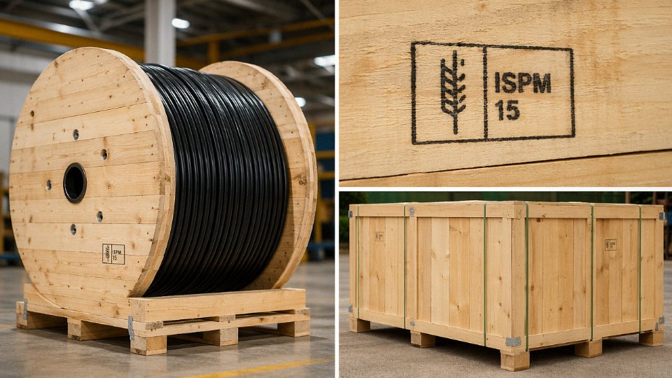
Drop cable typically ships on 500-foot, 1,000-foot, or 1,000-meter reels. The choice is not arbitrary. In a residential subdivision where each home run runs 150–250 feet, a 500-foot reel fits neatly into a single-family workflow — the installer cuts cleanly, waste sits under 10%, and the reel mounts on a standard saddle in the back of a service truck without needing a floor-standing dispenser. Move to MDU work or longer aerial runs, and 1,000-foot or 1,000-meter reels start making economic sense: fewer reel changes, less field splicing, lower per-foot packaging cost. The downside is truck inventory management — a pallet of 1,000-meter wooden reels is heavy and awkward, and if your crews are working out of compact vans rather than full-size cable trucks, you end up with partially spent reels rattling around for weeks, which is its own kind of waste. Match your reel size to your typical span length and your vehicle inventory before you specify packaging.
MOQ, Lead Times, and the Realities of Factory Scheduling
Most reputable coaxial manufacturers won’t quote firm lead times without knowing your reel format, jacket compound (PVC, LLDPE, or flooded for direct burial), and requested test documentation package. Typical MOQs from a volume manufacturer run somewhere in the range of 20,000–50,000 meters per SKU for standard RG-6 or RG-11, though this varies considerably depending on whether you’re ordering a catalog spec or a custom impedance-verified variant. Lead times for international orders generally fall between 25 and 60 days from purchase order to vessel loading — the wide range reflects copper availability, factory queue depth, and whether your order is large enough to justify a dedicated production run versus being slotted into a shared batch. Container consolidation adds time if your order doesn’t fill a full 20-foot container on its own, so it’s worth asking your supplier directly whether your volume qualifies for a dedicated load.
Copper Pricing and How to Structure Your Contract
Nearly every CATV coaxial cable quote is structured as a base price plus a copper adder referenced to LME daily spot prices. The copper content in a single reel of RG-6 is small, but across a multi-container order, even a 5–8% copper price swing during the production window can shift your landed cost meaningfully. A fixed-price contract sounds attractive when copper is rising but can leave money on the table when it corrects. In practice, many experienced procurement managers negotiate a hybrid: a fixed base price covering compounding, extrusion, and overhead, with the copper component indexed to the LME average over the production window rather than a single spot date. This distributes price risk more fairly and removes the incentive for either party to game the timing.
Standard CATV coaxial cable impedance is 75 ohms, not 50 ohmsTrue
75-ohm impedance is the industry standard for cable television distribution. 50-ohm coaxial is used in RF test equipment and Wi-Fi infrastructure. Mixing the two causes impedance mismatch, signal reflection, and measurable return loss degradation at every connector point.
Packaging, Crating, and the ISPM-15 Requirement
Wooden reels destined for export must comply with ISPM-15 phytosanitary regulations — heat treatment or methyl bromide fumigation with the official mark stamped on each piece of wood packaging. Skipping this step gets containers held at customs, sometimes for weeks. Beyond regulatory compliance, the crating design itself matters: reel flanges are vulnerable to forklift tine damage and to flange-to-flange pressure during container loading. Competent exporters pack reels with flange-clearance spacers and wrap each reel in moisture-barrier polyethylene before crating, particularly for shipments passing through humid transshipment ports. Ask your supplier for their standard export packing specification in writing before you approve the first order.
Supplier Qualification: What Actually Matters
ISO 9001 certification is table stakes — it tells you a quality management system exists, not that the factory uses it. The questions that separate capable suppliers from marginal ones are more specific. Can they provide in-line spark test records for every production reel, not just end-of-line samples? Do they maintain material traceability from copper rod lot to finished reel, so you can investigate a failure three months post-installation? Can they produce English-language test reports formatted for import customs and project compliance documentation without a two-week turnaround? These aren’t bureaucratic niceties; they’re the difference between a smooth project audit and a six-week dispute over whether the cable you installed meets the spec you contracted for.
Jinda’s five production bases distributed across China, covering roughly 470,000 m² of manufacturing space, mean that a multi-container order with a tight delivery window doesn’t necessarily require running a single line at maximum capacity — production can be allocated across facilities to maintain batch consistency and meet schedule without cutting corners on cure times or conductor annealing. For MSO tenders or national infrastructure rollouts where contract compliance requires consistent electrical performance across every reel in a multi-month supply program, that production depth is worth factoring into your supplier evaluation, not just the unit price on the quotation.
Installation Best Practices That Protect CATV Coaxial Cable Performance Over Its Service Life
You can specify the right cable grade, buy certified product, and still end up with a degraded plant if the installation is sloppy. Most premature CATV coaxial failures I’ve seen traced back to the field — a kinked drop behind a wall plate, a leaking F-connector on a strand-mounted tap, a cable stapled so tight the shield went oval. The cable’s datasheet performance means nothing once the geometry is compromised.
Minimum Bend Radius: A Number Worth Memorizing
RG-6 has a minimum bend radius of roughly 1.5 inches (38 mm) for a single, static bend and closer to 3 inches (76 mm) anywhere the cable will flex repeatedly — around a cabinet door edge, for example, or where a drop loops through a weatherhead. Violating this crushes the foam dielectric. The crush is permanent. Foam that’s been deformed doesn’t spring back, and the impedance discontinuity it creates will show up as a localized attenuation spike and return loss notch at that exact point on a sweep test. The frustrating part is that the damage is invisible from outside the jacket. You pull a sweep on a new install, you see a reflection artifact, and you spend two hours checking connectors before someone finds the kink behind the wall bracket.
RG-11, because of its larger diameter and stiffer dielectric, needs more room — typically 4 inches (100 mm) static minimum. Plan conduit sweeps and J-hooks accordingly before you pull.
Compression Connector Installation
Use the correct compression tool. That sounds obvious, but in practice technicians carry one generic tool and swap connector brands job to job without verifying the compression OD matches the cable’s actual jacket and dielectric diameter. A connector dimensioned for a 6.86 mm dielectric installed on a cable with a 6.65 mm dielectric will never fully seat, leaving a small air gap at the interface. That gap is a direct water ingress path and a source of high return loss — the single most common cause of DOCSIS modem re-ranging events I’ve encountered in residential drop work.
Always verify connector series against the specific cable’s published dimensions, not just the cable designation. Two cables both labeled “RG-6” from different manufacturers can differ by 0.3–0.5 mm in dielectric OD. It matters.
Weatherproofing Outdoor Connections
Self-amalgamating tape applied in a half-lap wrap, starting below the connector and finishing above it, remains the field standard for exposed F-connector ports. Weatherproof boot caps are faster and acceptable for strand-mounted hardware where the cap seats properly, but they don’t conform to irregular connector bodies the way tape does. Flooded connector designs — where the inner cavity is pre-filled with a dielectric sealant — are worth the small cost premium on any outdoor tap or splitter port that won’t be revisited for years.
Moisture in a single unsealed connector doesn’t just degrade that drop. Corrosion products migrate into the center conductor oxidizing the contact surface, increasing resistance, and in humid climates this can happen within a single wet season.
Moisture intrusion at a single outdoor F-connector can cause DOCSIS modem re-ranging events affecting the entire dropTrue
Water ingress raises contact resistance and introduces impedance discontinuities that increase return loss and noise, directly affecting the signal-to-noise ratio the DOCSIS modem sees during ranging and data transmission.
Staple and Clip Spacing for Indoor Runs
Maximum 24-inch (600 mm) intervals on horizontal indoor runs. Use cable staples sized for the cable’s actual OD — an undersized staple driven flush compresses the jacket enough to distort the braid geometry underneath, and that distortion is a shield discontinuity. You won’t see it on a short sweep, but it contributes to cumulative return loss on longer in-wall runs.
Don’t use staples at all on runs that need to be pulled later. Nail-in clips with a smooth plastic saddle are worth the extra two minutes per clip.
Grounding and Bonding
NEC Article 820 requires the coaxial cable shield to be bonded to the building’s grounding electrode system at the point of entry. This isn’t optional, and it’s not just about lightning — though lightning is the dramatic consequence. Ground loop noise between the cable plant ground and the building ground is a more common, quieter problem that shows up as low-level hum or noise floor elevation on signal analyzers. A properly bonded ground block at entry, connected with 14 AWG or heavier conductor run as short and straight as practical to the electrode, handles both issues.
Storage and Handling on Site
Standard PVC-jacket RG-6 is rated for installation between roughly -20°C and +60°C. In cold climates, pulling cable that’s been sitting in an unheated van overnight at -15°C means working with a jacket that’s stiff and prone to cracking if bent sharply. Let the reel warm up. In summer on exposed job sites, a reel sitting in direct sun on asphalt can easily exceed 60°C surface temperature, which softens the jacket enough that stapling or clamping can permanently indent it.
Never roll a reel across gravel. It sounds like a minor handling note until you find a series of jacket nicks that compromise the moisture barrier on a buried or outdoor run — at which point the cable needs to be replaced, not repaired.
Frequently Asked Questions About Cable TV Cable Types
Can I use RG-59 for cable TV instead of RG-6?
Short answer: only in very limited circumstances, and probably not yours. For runs under roughly 20–25 feet carrying analog CATV signals below 550 MHz, RG-59 will technically pass signal — but it’s marginal even there. The moment you’re feeding a DOCSIS modem, a satellite IF leg, or any drop longer than 50 feet, RG-59’s higher attenuation (around 7.5–8.5 dB per 100 feet at 100 MHz versus RG-6’s 5.5–6.0 dB) eats into your link budget fast enough to cause real problems: pixelation, modem sync drops, or complete loss of higher-frequency channels. RG-6 is the minimum acceptable standard for anything built after roughly 1995. RG-59 still shows up in older residential installs and in some low-frequency CCTV runs, but if you’re specifying new CATV drop cable, don’t specify RG-59.
What is the difference between 50-ohm and 75-ohm coaxial cable?
These are not interchangeable, and mixing them in a system causes real damage to signal quality. The 75-ohm characteristic impedance is optimized to minimize signal attenuation in video and broadband distribution — it’s what every CATV system, satellite receiver, and cable modem port is designed around. The 50-ohm standard exists for transmitter and RF test equipment applications where power handling matters more than loss minimization. Plug a 50-ohm cable into a 75-ohm CATV port and you create an impedance mismatch. That mismatch causes signal reflections and standing waves, which show up as ghosting, reduced SNR, or upstream modem errors that are genuinely difficult to trace back to the cable when you’re troubleshooting remotely. The connectors look identical. Label your cable.
How far can a cable TV signal travel on RG-6 before needing amplification?
At 550 MHz, RG-6 attenuates somewhere around 6 dB per 100 feet — though the exact figure shifts with temperature (cold runs slightly better, hot days hurt you) and varies by manufacturer. A typical CATV drop might deliver +10 dBmV at the tap port and require no less than −6 dBmV at the subscriber’s outlet for reliable DOCSIS operation. That’s a 16 dB budget, which gets you roughly 250–280 feet on RG-6 before you need a distribution amplifier. Go to 750 MHz or 1 GHz and that distance shrinks noticeably. If you’re running longer drops — say, to a detached garage or a second structure on the property — RG-11 buys you back significant headroom before you reach for an amplifier.
RG-6 coaxial cable attenuates approximately 5.5–6.0 dB per 100 feet at 100 MHz under standard conditionsTrue
This range is consistent with published SCTE and manufacturer specifications for standard RG-6 quad-shield and dual-shield constructions; exact values vary with center conductor gauge, dielectric type, and ambient temperature
Is quad-shield RG-6 necessary for residential CATV?
In practice, it depends heavily on the RF environment around the property. Quad-shield construction — two foil layers and two braid layers — provides meaningfully better ingress rejection than dual-shield, which matters most when you have strong AM broadcast towers, cellular base stations, or amateur radio transmitters nearby. In a quiet suburban environment with no obvious RF interference sources, dual-shield or tri-shield RG-6 performs fine and costs less. Where I’d default to quad-shield without hesitation: any installation near a cell tower, any home in a dense urban RF environment, and any run that passes close to electrical panels or elevator motor rooms. The price delta is usually small enough at bulk purchase volumes that some contractors just spec quad-shield across the board to eliminate callbacks.
What cable is used for cable TV underground burial?
Standard PVC-jacketed RG-6 is not rated for direct burial. Full stop. Buried without the right jacket, it absorbs ground moisture through the outer jacket over months, corroding the foil shield and eventually the braid — you won’t see the problem until you have a flooded shield and severe signal loss a year or two after installation.
Direct-burial CATV drop cable uses RG-6 or RG-11 with a flooded (gel-filled) polyethylene jacket specifically designed to block moisture ingress. Some versions include an integrated steel messenger wire for aerial self-support, which is useful if the same run transitions from buried to aerial between buildings. Specify the burial depth too — most codes want at least 18 inches for CATV drop, 24 inches if the trench crosses a driveway. A conduit pull is always cleaner if you can do it; it makes future cable replacement a same-day job instead of another dig.
Does fiber optic cable replace coaxial cable in cable TV networks?
Fiber has taken over the backbone and feeder segments of virtually every modern HFC network — the economics and bandwidth capability made that transition straightforward. But the final drop from the optical node or ONT to the subscriber’s home still runs on coaxial cable in the overwhelming majority of installed cable TV systems worldwide. Full fiber-to-the-home deployments are growing, particularly in greenfield builds and in areas where operators are upgrading to meet DOCSIS 3.1 or DOCSIS 4.0 demands. Still, replacing the coaxial drop plant in a mature cable system represents an enormous capital commitment, and most operators are extending coaxial plant life rather than replacing it wholesale. Coaxial drop cable will remain the dominant last-mile medium for cable TV for at least another decade in most markets.
How do I verify that a coaxial cable supplier meets CATV specifications?
Don’t rely on a datasheet alone. Request actual test reports showing attenuation versus frequency across a sweep from 5 MHz to at least 1 GHz, structural return loss (SRL), characteristic impedance, and shield coverage percentage — then compare those numbers against SCTE 74 or IEC 61196-4 limits rather than accepting the supplier’s own pass/fail claims. Ask for the ISO 9001 certificate and check the issuing body is a recognized accreditation authority. Request a sample reel — even 50 meters — before committing to a bulk order, and run your own bench measurements. Attenuation at 1 GHz and shield effectiveness are the two specs where cut-rate production shows up fastest. A supplier who pushes back on sample requests before a large order is telling you something.