You’ve ordered the wrong cable before. Maybe it was labeled “coaxial” on the reel but spec’d for satellite rather than cable TV distribution, and your installer found out the hard way when signal levels dropped 4 dB short of threshold at the tap — meaning a truck roll, a delay, and a contractor standing around billing you hourly. That mix-up almost always comes down to not knowing the correct name and specification of the wire your system actually requires.
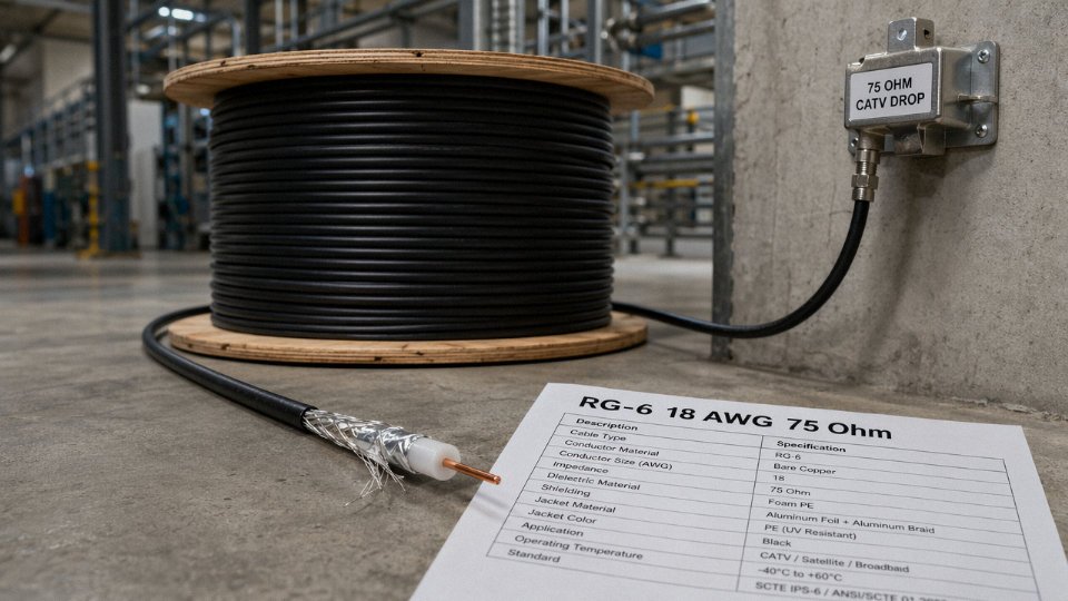
Cable TV wire is called coaxial cable — specifically RG-6 coaxial cable with 75-ohm impedance. It consists of a center copper conductor, a dielectric insulator, one or more metallic shielding layers, and an outer jacket. For cable TV and HFC (hybrid fiber-coaxial) distribution, RG-6 is the dominant type, though RG-11 is used for longer trunk runs.
What’s less obvious is that “RG-6” is not a single product. Depending on the shielding configuration, conductor material, jacket rating, and frequency ceiling of your system — especially now that DOCSIS 3.1 networks are pushing past 1 GHz — you can buy cables sold under the same name that will perform very differently once they’re in the wall or buried underground. The naming is where most procurement errors start.
Coaxial Cable Anatomy: Every Layer and Why Each One Matters for Cable TV Signal Quality
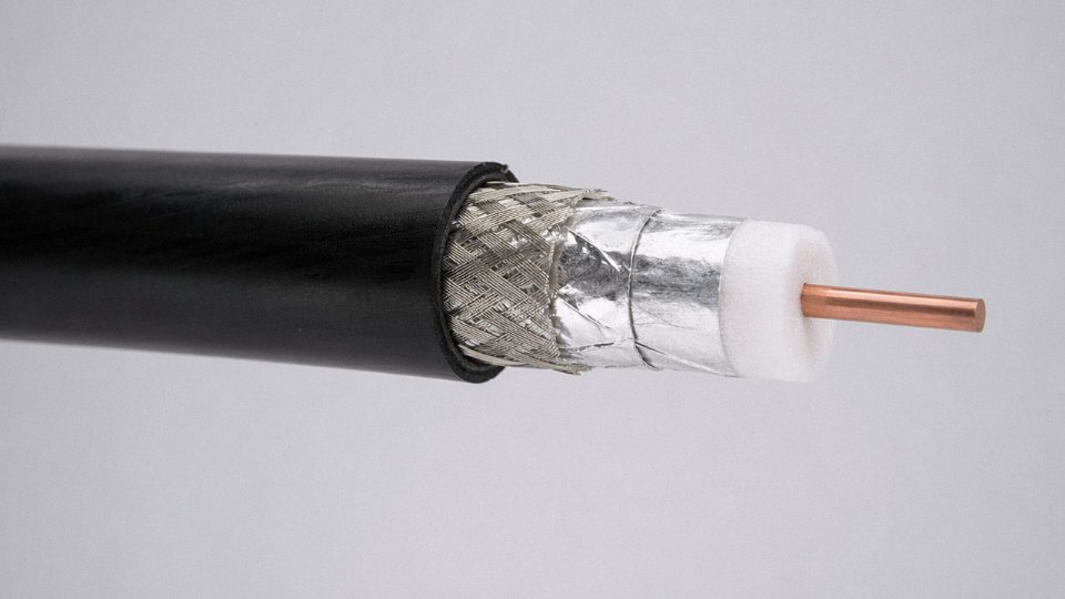
Cut a piece of RG-6 crosswise and you’re looking at five distinct layers, each doing a specific job. Get any one of them wrong in manufacturing or in field installation and you pay for it — in dB loss, in interference, in trucks rolling to a service call. Here is what each layer actually does.
Center Conductor
This is where signal propagation begins, and the material choice matters more than most installers admit. Solid bare copper (BC) is the benchmark: resistivity around 1.72 µΩ·cm, DC resistance for 18 AWG solid copper running roughly 6–7 Ω per 1,000 feet depending on exact draw diameter. Copper-clad steel (CCS) bumps that DC resistance up to 15–20 Ω per 1,000 feet — workable for short residential drops where you’re pulling coax 30–50 feet from a splitter to a TV, but genuinely problematic on longer trunk runs because the steel core doesn’t carry RF at low frequencies the way copper does. The skin effect does concentrate RF energy toward the surface above a few MHz, which is why CCS gets away with it on high-frequency signals, but any run powering a line amplifier via DC over the coax needs solid copper or you’re dropping supply voltage before the amp even sees it. Copper-clad aluminum (CCA) sits in uncomfortable middle ground: lighter, cheaper, but prone to galvanic corrosion at connectors and noticeably higher loss on extended runs. I wouldn’t specify CCA for anything other than a short, dry, indoor installation where cost is the only driver.
Dielectric
The foam polyethylene (foam PE) dielectric used in broadcast-grade RG-6 gives a velocity of propagation (VoP) around 82–87%, versus roughly 66% for solid PE. Higher VoP means lower insertion loss for a given physical length — and in an HFC distribution network where signals travel through cascade amplifiers, every fraction of a dB counts. The dielectric constant of foam PE sits around 1.4–1.6 compared to 2.3 for solid PE, and that lower constant is the direct physical reason attenuation drops. Air-spaced foam constructions push VoP even higher, toward 88–93%, and show up in trunk cable for headend-to-node runs, though they’re more sensitive to moisture ingress if the jacket gets nicked.
Inner Foil Shield
An aluminum-polyester (Mylar-bonded) laminate wrapped at 100% overlap — no gaps. Its primary job is blocking high-frequency interference above roughly 50 MHz, precisely the band where cable TV signals live. The foil provides continuous coverage where braid weaves leave small openings. Spec documents for CATV applications typically mandate 100% foil coverage; anything less and you’re chasing ingress gremlins at 600–700 MHz, usually during wet weather when soil conductivity changes around buried runs.
Braid Shield
Over the foil goes a woven braid — aluminum or tinned copper — at coverage densities from around 60% on economy cable up to 95–98% on quality quad-shield constructions. The braid handles low-frequency shielding and, critically, provides the mechanical ground path at connectors. Quad-shield cable adds a second foil plus a second braid layer. It gets specified in dense MDU installations, near power substations, or anywhere RFI ingress is a documented problem. The extra shielding buys you another 10–20 dB of isolation; whether you need that depends entirely on the RF environment, not just habit.
Outer Jacket
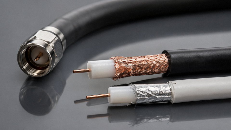
Black jacket means outdoor-rated. That’s not a convention — it’s a material signal. Black PVC or LLDPE compounds carry carbon black for UV stabilization; white and grey indoor jackets skip that additive and will chalk and crack within a season in direct sun. Properly rated outdoor cable handles -40 °C to roughly +85 °C. Direct-burial variants add a gel-filled or thicker LLDPE jacket; aerial versions are often lashed to a messenger wire or use an integrated figure-8 construction. LSZH (low-smoke zero-halogen) jackets appear in plenum and tunnel installations where fire codes restrict PVC off-gassing.
How All This Produces 75 Ohms
Characteristic impedance is a function of the dielectric constant and the ratio of outer conductor inner diameter to center conductor outer diameter. Cable TV standardized on 75 Ω — not the 50 Ω used in RF test and wireless infrastructure — because 75 Ω minimizes signal loss in a coaxial line terminated into typical antenna and video impedances. At the frequencies where broadcast video distributes, a 75 Ω system delivers lower insertion loss than 50 Ω for the same conductor geometry.
RG-6 quad-shield coaxial cable carries a standard characteristic impedance of 75 ohms per IEC 61196True
IEC 61196 specifies 75 Ω ±3 Ω for RF coaxial cables used in cable television distribution systems; this is the globally recognized standard impedance for CATV applications.
Tolerance matters in production: IEC 61196 allows ±3 Ω, but a sloppy manufacturing run that drifts to the edge of that window will produce measurable return loss degradation, particularly above 750 MHz where modern DOCSIS plant operates.
RG-6, RG-59, and RG-11: Choosing the Right Cable TV Coax for Each Segment of a Distribution Network
Cable TV coaxial cable is not a single product. Walk into any serious distributor and you’ll find at least three distinct types on the shelf — RG-59, RG-6, and RG-11 — and getting the selection wrong doesn’t just produce a marginal performance hit. It means rework, signal complaints from subscribers, or a trunk run that needs to be re-pulled within two years because the original spec was undersized.
RG-59: The Legacy Option and Its Real Ceiling
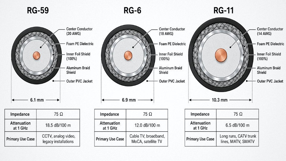
RG-59 uses a 20 AWG center conductor and maintains the standard 75-ohm characteristic impedance common to all cable TV coax. For decades it was the default residential drop cable, and you’ll still encounter it in older MDU buildings and CCTV installations. Short analog runs — say, under 150 feet to a standard-definition outlet — it handles fine.
The problem is frequency. RG-59’s attenuation climbs steeply above 400 MHz, which is where the useful bandwidth of any modern HFC system lives. For HD signals, most experienced installers cap RG-59 runs at roughly 150–225 feet, and that ceiling depends heavily on connector quality and how many splitters sit in the path. Push it to 300 feet feeding a DOCSIS modem and expect upstream noise problems that are genuinely difficult to diagnose. In practice, RG-59 has no place in new residential cable TV work.
RG-6: The Current Default for Residential Drops and MDU Wiring
RG-6 is the industry standard drop cable, and for good reason. The 18 AWG center conductor — solid copper or copper-clad steel (CCS) depending on grade — gives meaningfully lower attenuation than RG-59 across the entire cable TV band. Typical attenuation figures for a solid-copper RG-6 run roughly 1.0–1.4 dB per 100 feet at 50 MHz, 2.0–2.8 dB at 200 MHz, 3.0–4.2 dB at 400 MHz, 5.0–6.5 dB at 900 MHz, and around 6–8 dB at 1 GHz — though exact values shift depending on dielectric grade, conductor purity, and foil quality. CCS center conductors run slightly higher attenuation and are not ideal for long runs or upstream-heavy DOCSIS 3.1 deployments.
Maximum recommended drop length before a passive splitter is typically 200–300 feet, again dependent on the node’s output level and how many downstream outlets share the signal. Beyond that, you need either an active amplifier or a cable upgrade.
On shielding: quad-shield RG-6 is mandatory in environments with significant RF ingress — near cellular base stations, in dense urban MDU buildings where neighboring Wi-Fi and LTE signals saturate the environment, or in any MRI-adjacent installation. Dual-shield is acceptable for a typical single-family residential drop in a low-interference suburban environment. The difference in material cost per 100 meters is modest; the cost of a service call because upstream noise is corrupting modem registration is not.
RG-11: Lower Attenuation for Feeder and Trunk Segments
RG-11 uses a 14 AWG center conductor and delivers roughly 35–45% lower attenuation than RG-6 at 1 GHz — the exact reduction depends on dielectric type and foil construction. That performance advantage makes it the right choice for feeder runs from the node to the first distribution point, underground trunk segments, aerial strand-lashed drops exceeding 300 feet, and any backbone run where re-amplification would otherwise be required.
The trade-offs are real. RG-11 has a larger outer diameter, a minimum bend radius that creates headaches in tight conduit runs, and a noticeably higher cost per meter. It is also heavier, which matters on aerial installations where strand tension calculations already leave little margin.
RG-11 coaxial cable provides significantly lower signal attenuation than RG-6 at cable TV frequencies, making it appropriate for long trunk and feeder segmentsTrue
RG-11's larger 14 AWG center conductor reduces resistive losses compared to RG-6's 18 AWG conductor, resulting in roughly 35–45% lower attenuation at 1 GHz depending on construction, which is well-documented in IEC 61196 and SCTE specifications.
Side-by-Side Comparison
| Parameter | RG-59 | RG-6 | RG-11 |
|---|---|---|---|
| Center conductor gauge | 20 AWG | 18 AWG | 14 AWG |
| Impedance | 75 Ω | 75 Ω | 75 Ω |
| Outer diameter (approx.) | ~6.1 mm | ~6.9 mm | ~10.3 mm |
| Attenuation at 1 GHz (per 100 ft) | ~10–13 dB | ~6–8 dB | ~3.5–5 dB |
| Minimum bend radius | ~25 mm | ~35 mm | ~55–65 mm |
| Typical price per 100 m (OEM reel) | Lower | Mid | ~1.5–2× RG-6 |
| Primary use case | CCTV, legacy analog | Residential drops, MDU | Feeder, trunk, long runs |
Price ranges depend on copper market rates, conductor type (solid copper vs. CCS), and order volume. Budget figures should always be validated against current LME copper pricing.
Governing Standards
The cables covering these three types fall under IEC 61196-1 for general coaxial cable requirements and IEC 61196-6 specifically for drop cables used in cable TV distribution. European installations typically reference EN 50117, which defines coaxial cable performance classes (A through A++). North American cable operators and headend engineers work from SCTE/ANSI specifications — particularly SCTE 74 for drop cables — which define attenuation limits, return loss, and structural return loss across the full DOCSIS operating band. If you’re specifying cable for an international project, it’s worth confirming which standards the local operator’s network audit requires before committing to a production run, because EN 50117 Class A and SCTE 74 are not identical in every requirement.
How Cable TV Signal Travels Through Coaxial Wire: RF Physics, Frequency Bands, and Loss Budgets
RF energy inside a coaxial cable does not behave the way DC current does. Understanding that distinction — really understanding it, not just knowing the words — is what separates engineers who spec cable correctly from those who blame the amplifier for problems that started at the reel.
Skin Effect: Why the Surface of the Conductor Does All the Work
At cable TV frequencies, alternating current crowds toward the outer skin of the center conductor. The depth of that skin — literally the skin depth — shrinks as frequency rises. At 100 MHz it is already only a few microns into the copper. By 1 GHz it is thinner still.
This is why copper-clad steel (CCS) center conductors are perfectly acceptable for carrying the RF signal in a distribution cable. The steel core contributes almost nothing to signal conduction at these frequencies; the thin copper cladding handles it. Where CCS fails you is in any application where DC or low-frequency current must pass through the center conductor — powering a line amplifier, feeding a masthead LNA, or any PoE-over-coax scheme. Steel resistivity is roughly six to eight times higher than copper, so voltage drop on a CCS conductor under DC load can be high enough to starve or damage powered equipment. Specify solid bare copper (BC) center conductors the moment power-passing enters the design. This is one of those spec details that gets missed in procurement when someone just orders “RG-6” without reading past the part number.
Insertion Loss and the Square-Root Relationship
Attenuation — insertion loss — is the primary cable specification in any distribution design. It is expressed in dB per unit length, usually per 100 feet or per 100 meters depending on which part of the world you are in. The fundamental physics force attenuation to scale roughly with the square root of frequency, which means doubling frequency does not double your loss, but it does increase it meaningfully. At 100 MHz, a standard RG-6 quad-shield cable will run somewhere around 1.5–2.5 dB per 100 feet; push to 1 GHz and you are looking at roughly 6–8 dB per 100 feet, give or take depending on conductor diameter, dielectric foam density, and temperature.
Temperature matters more than most installers admit. Attenuation rises in summer. A cable sized for a 20°C environment can be 10–15% lossier on a hot rooftop in July. For a typical HFC node-to-subscriber path — say 300 feet of drop cable from the tap to the subscriber’s first splitter — cumulative insertion loss across the downstream band (54 MHz to 1 GHz) might range from roughly 5 dB at the low end of the spectrum to 20–25 dB at the high end. That slope has to be accounted for in the amplifier equalization and tap design; otherwise the high-frequency DOCSIS channels arrive 15 dB weaker than the low-frequency analog or broadcast channels.
Return Loss and Why Reflections Kill DOCSIS Performance
Every impedance discontinuity in the cable path — a poorly seated F-connector, a sharp kink that deformed the dielectric, a wrong cable type spliced mid-run, a corroded crimp — sends a portion of the signal back toward the source as a reflection. Return loss measures how much is reflected; higher numbers mean less reflection and a cleaner system. Structural return loss (SRL) is the more specific measure, capturing distributed reflections caused by periodic dimensional variations in the cable itself during manufacturing.
In a DOCSIS network, reflections are not just a nuisance. The OFDM and QAM modulation schemes used in DOCSIS 3.0 and 3.1 are sensitive to the echo effects that reflections create, especially in the upstream path. A system running at 256-QAM or higher can see uncorrectable errors, throughput collapse, or complete modem dropout when return loss at any connector dips below roughly 14–18 dB. Good-quality quad-shield RG-6 cable manufactured to IEC 61196-1 tolerances will hold structural return loss well above that threshold over its service life — provided it is installed without sharp bends and terminated with proper compression connectors seated fully against the dielectric.
Quad-shield coaxial cable provides greater than 100 dB shielding effectiveness at cable TV frequenciesTrue
Quad-shield coax combines two foil layers and two braid layers; when properly manufactured and terminated, this construction routinely exceeds 100 dB isolation per IEC 61196 and SCTE specifications, confirmed by independent cable lab testing.
Frequency Plans and Why Modern Cable Must Cover Extended Spectrum
Legacy HFC systems ran downstream from roughly 54 MHz to 750 or 860 MHz, with upstream confined to 5–42 MHz — a narrow, noise-prone return path. DOCSIS 3.1 pushed downstream to 1.002 GHz on legacy plant and up to 1.2 GHz on extended spectrum deployments. Full Duplex DOCSIS expands upstream capacity out to 204 MHz, using the same spectrum simultaneously for both directions.
The cable plant has to physically support these frequencies. A cable whose shield or dielectric was designed for 860 MHz systems will show degraded shielding effectiveness and higher-than-rated attenuation when pushed to 1.2 or 1.8 GHz. This is not theoretical — operators upgrading to DOCSIS 3.1 on older plant have found that sections of cable that tested fine at legacy frequencies became the weakest links in the system once extended spectrum was activated. Specifying cable rated explicitly to 1.8 GHz, with attenuation and shielding data provided at those frequencies, is the only defensible approach for any greenfield installation today.
Shielding and the LTE/5G Problem
In dense urban environments, cable TV drop cables share physical space — and increasingly, frequency spectrum — with LTE and 5G cellular signals. The C-band 5G deployments in particular overlap with portions of the upper cable TV downstream spectrum. A dual-shield cable with only 75–85 dB of shielding can allow ingress at these frequencies that mimics noise or interference in the DOCSIS upstream or drives up the noise floor across the downstream. Quad-shield construction — two aluminum foil layers and two braid layers — is not over-engineering for a city rooftop or a dense apartment building; it is simply the right spec.
Maintaining Signal Levels at the Subscriber Tap
At the subscriber tap, downstream signal levels need to stay within a fairly tight window, typically 0 dBmV to roughly +15 dBmV for standard cable TV operation, though DOCSIS specifications put it closer to −15 to +15 dBmV depending on channel type. Too low and the receiver cannot lock; too high and the amplifier or modem input is overdriven. Maintaining that window across a multi-dwelling unit or campus network — with drop lengths that vary from 30 feet to 300 feet and splitters taking 3.5–7 dB per port — depends entirely on starting with accurate attenuation figures for the actual cable being installed and building a real loss budget before a single connector is crimped.
Trunk, Feeder, and Drop Cable: Understanding the Three-Tier Coaxial Architecture of a Cable TV Network
A cable TV network isn’t a single wire from headend to television. It’s a layered system, and the cable specification at each tier is dictated by physics — specifically, how far a signal has to travel and how many subscribers it has to reach before the next amplification point. Getting the wrong cable into the wrong tier is one of those procurement mistakes that looks fine on paper and causes chronic headaches in the field.
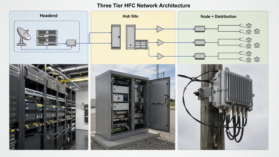
Trunk Cable: Headend to Node
The backbone of a traditional hybrid fiber-coaxial (HFC) outside plant is hardline trunk cable. These are typically designated by their aluminum outer conductor diameter — QR540, QR715, QR860 — where the number represents the outer conductor’s nominal diameter in hundredths of an inch. A QR715, for example, has a 0.715-inch solid aluminum outer conductor over a foam-polyethylene dielectric. Attenuation on these cables runs roughly 0.8–1.4 dB per 100 feet at 750 MHz depending on diameter, which is what allows amplifier spacings of 500 to 2,000 meters in real outside-plant designs. The solid aluminum sheath does double duty: it’s both the RF return conductor and the mechanical structure protecting the dielectric core from moisture intrusion and rodent damage. Field splicing these cables requires swept-back connectors and torque-spec installation — under-torqued compression fittings are a chronic source of ingress noise that’s devilishly hard to locate once the cable is buried.
Feeder Cable: Node to Distribution Point
Coming out of the optical node, the feeder layer — sometimes called distribution cable — steps down in diameter. RG-11 or mid-size hardline (QR412 range) lashed to a messenger strand or run direct-burial carries signal to neighborhood distribution amplifiers and passive taps. These runs serve clusters of 25–200 homes per strand, depending on tap values and cascade depth. Aerial installation is still standard in much of Southeast Asia, sub-Saharan Africa, and parts of Latin America; direct-burial is more common in newer Middle Eastern deployments where municipal requirements and aesthetics drive underground runs. Either way, the cable needs UV-stable jacketing for aerial or a flooded core for direct-burial, and specifying the wrong variant is a surprisingly common procurement error on first-time international projects.
Drop Cable: Tap to Subscriber
This is where volume gets serious. Drop cable — almost always RG-6 quad-shield or dual-shield coax — represents the majority of cable meterage in any network deployment by a wide margin. Runs from the tap port to the subscriber’s set-top box or cable modem are typically 15 to 150 meters. Quad-shield construction (dual foil plus dual braid) provides the shielding effectiveness needed to suppress ingress in dense urban environments, particularly in MDUs where the cable passes through electrical closets and along elevator shafts.
RG-6 quad-shield coaxial cable is the highest-volume cable type purchased in any CATV network build or upgrade project.True
Drop cable runs from tap to subscriber represent far more individual cable segments than trunk or feeder, and each subscriber requires a dedicated drop, making RG-6 the dominant cable type by total meterage and unit count in CATV procurement.
Fiber-Deep and Node+0: How Modern Upgrades Reshape Procurement
DOCSIS 3.1 and Full Duplex DOCSIS 4.0 deployments are pushing fiber progressively deeper — node+0 architectures eliminate coaxial amplifier cascades entirely by placing the optical node within direct drop distance of subscribers. That means shorter RG-6 runs, virtually no feeder-layer hardline, and dramatically reduced amplifier maintenance overhead. For procurement managers, this shifts the bill of materials heavily toward drop cable and fiber, with hardline trunk essentially disappearing from the BOM on greenfield node+0 builds. Existing operators upgrading brownfield networks usually see a mixed procurement profile — some trunk repurposed, feeder partially retained, and drop cable replaced or extended.
In-Building Wiring: MDUs and Commercial Buildings
In multi-dwelling units and commercial buildings, the coax network doesn’t end at the building entry point. Structured coax wiring distributes signal through passive splitter trees to individual outlets, and every splitter insertion introduces 3.5–7 dB of loss depending on the splitter design and frequency. In a 12-unit building with a two-way splitter feeding two 6-way splitters, you can easily consume 15–18 dB before you’ve run a single meter of drop cable. Active distribution amplifiers compensate, but they require power and introduce noise figure into the return path — a real concern for DOCSIS upstream channels in the 5–85 MHz band (or 5–204 MHz under extended spectrum plans). Signal level management in MDUs is genuinely one of the more tedious parts of a cable TV plant design, and it’s where cheap quad-shield drop cable with marginal shielding causes the most subscriber-visible problems.
Jinda’s five manufacturing bases in China support volume production across all three tiers: hardline trunk cable, RG-11 feeder, and RG-6 drop cable in both dual-shield and quad-shield configurations. For CATV operators and system integrators procuring across Asia, Africa, the Middle East, and Latin America — where a single network expansion project can require hundreds of thousands of meters of drop cable alone — having a manufacturer with dedicated production lines for each cable type, rather than a generalist running short batches, makes a measurable difference in lead time consistency and lot-to-lot dimensional stability.
Connector Types and Termination Standards That Directly Affect Coaxial Cable TV Performance
A cable is only as good as its worst termination. That’s not a platitude — it’s something you learn the hard way when a freshly installed MDU building comes back with intermittent signal complaints and you spend two days tracing the fault to a bag of twist-on F connectors the subcontractor sourced off the lowest-cost shelf.
The F-Type Connector: Global Standard, But Not All Equal
The F-type connector is the workhorse of cable TV drop wiring worldwide. Its geometry is simple — a threaded barrel that captures the cable’s prepared center conductor as the pin — but that simplicity is deceptive. There are three termination methods in common use: compression, crimp, and twist-on.
Twist-on connectors have no legitimate place in a permanent installation. They work loose, they admit moisture, and they fail SCTE 01 retention and pull-force tests. Crimp-type connectors are better — adequate for dry indoor runs where you’re not expecting thermal cycling — but the ferrule crimp doesn’t seal the cable jacket reliably against the elements. Compression-type F connectors, where a sleeve is driven forward by a compression tool to lock the jacket and create a moisture-resistant seal around the cable, are what SCTE 01 and IEC 61169-24 actually require for outdoor and MDU use. No exceptions in a properly specified network.
Only compression-type F connectors meet SCTE 01 and IEC 61169-24 requirements for outdoor and MDU cable TV drop installations.True
SCTE 01 specifies minimum pull-out force, moisture resistance, and contact retention requirements that twist-on and most crimp-style connectors cannot reliably meet in outdoor or multi-dwelling unit environments. IEC 61169-24 similarly mandates environmental sealing performance that only compression termination consistently delivers.
BNC, Type-N, and DIN 7-16: When F-Type Isn’t the Right Tool
BNC connectors appear regularly in broadcast headends and CCTV distribution frames. The critical procurement detail is impedance: cable TV and CCTV distribution requires the 75-ohm BNC version, not the 50-ohm variant used in RF lab and wireless applications. They look nearly identical. A 50-ohm BNC on a 75-ohm distribution path introduces a reflection that can add 6–10 dB of return loss degradation at the mating point — enough to upset a sensitive QAM receiver. Mating cycle ratings typically run 500–1,000 cycles depending on manufacturer and plating quality; in high-patch environments, that number matters.
For hardline trunk and feeder cable, the connectors change entirely. Type-N connectors handle frequencies up to roughly 11 GHz and are rated for outdoor use, but they require correct torque — usually 1.1–1.4 N·m depending on connector size and series — and wrapping with self-amalgamating tape over the mated pair is standard practice on aerial plant. DIN 7-16 connectors are common in European trunk applications and underground splice closures; they offer better third-intermodulation products than Type-N at high power levels and are preferred where the node amplifier feeds are long. Both types require weather boots or enclosure sealing. Skipping that step on an aerial run in a climate with freeze-thaw cycles is how you get a service call in February.
Termination Faults and What They Actually Cost You
Cold solder joints — usually from a tech rushing through connector prep on a headend patch panel — typically increase return loss by 3–6 dB at the fault point. That sounds modest until it combines with two other marginal connections in a cascade and your downstream MER drops below threshold on a 256-QAM channel.
Water ingress is slower and more insidious. A drop cable with a poorly compressed connector on the exterior wall fitting will wick moisture under the jacket over months. Field measurements on failed drops routinely show 10–15 dB of additional attenuation on the affected span after roughly six months of exposure — the aluminum foil shield begins oxidizing and the foam dielectric absorbs moisture, both of which degrade the cable’s velocity of propagation and thermal noise floor simultaneously. By the time the subscriber calls, the cable is often unrecoverable.
Dielectric trim length on RG-6 is another fault that’s easy to make and hard to diagnose. If you leave too much dielectric protruding, the center conductor doesn’t seat fully in the compression connector body; too little and the impedance discontinuity at the air gap raises structural return loss by amounts that matter on DOCSIS 3.1 upstream channels. Most connector manufacturers spec this to ±0.5 mm. In practice, technicians doing high volumes of terminations in the field need a proper prep tool, not a utility knife.
Testing After Installation
No drop should be released without a signal level measurement at the subscriber outlet. A CATV signal level meter reading downstream carrier level and carrier-to-noise ratio takes about 90 seconds and catches bad connectors, wrong cable type, and amplifier miswiring before a customer ever touches the equipment. For DOCSIS deployments, MER measurement — typically target values of 33–36 dB on 256-QAM, depending on the plant design — at the outlet gives you a more sensitive picture of cumulative termination quality than simple level alone.
Return path sweep testing before service activation is increasingly non-negotiable on DOCSIS 3.1 plant. The upstream band now extends to 204 MHz under Extended Spectrum DOCSIS configurations, and ingress from poor connectors on the return path is additive across every subscriber on the node. One bad termination can degrade upstream capacity for an entire serving area.
Jinda’s Cable Production Quality Controls
Connector quality only matters if the cable itself is consistent to specification. At Jinda, every coaxial cable reel goes through 100% conductor DC resistance testing and high-voltage dielectric testing at 3 kV DC before leaving the production line — not sampled, 100%. Structural return loss is measured per IEC 61196 to verify impedance uniformity along the cable length, which is the factory-side check that catches foam dielectric density variations and shield coverage inconsistencies. Third-party certification to CE, RoHS, and REACH is standard for cables destined for European and international markets. For procurement managers specifying cable for a large HFC buildout or MDU project, those test records should be part of the delivery documentation, not an afterthought.
Outdoor, Direct-Burial, and Aerial Cable TV Wire: Jacket and Armor Specifications for Long-Term Infrastructure Durability
Getting the signal physics right inside the cable means nothing if the jacket fails two winters into a 20-year infrastructure project. Outdoor cable TV coax lives in a punishment environment — UV radiation, soil chemistry, freeze-thaw cycling, wind, ice, and in more places than engineers like to admit, rodents. Specifying the wrong jacket compound or skipping armor on a direct-burial run are the kinds of procurement decisions that show up three years later as a truck roll and a service outage, not as a line item on the original bill of materials.
UV Stabilization: Why Jacket Compound Choice Defines Service Life
Standard PVC jackets begin to chalk, crack, and embrittle after roughly 3–5 years of direct sun exposure. That degradation isn’t cosmetic — once the jacket cracks, moisture ingresses into the braid and foil layers, and you get the kind of slow impedance creep and noise floor rise that’s genuinely hard to diagnose without cutting the cable open.
Outdoor-rated RG-6 uses HDPE or LLDPE jacket compounds loaded with carbon black at 2%–3% by weight. That carbon black loading is doing real work: it scatters and absorbs UV before it reaches the polymer backbone, and properly compounded HDPE jackets at that loading level can sustain 20-plus years of direct outdoor exposure without structural failure. The exact service life depends on UV index at the installation latitude, whether the cable runs in open air or in conduit, and ambient peak temperatures. A cable on a rooftop in Riyadh ages faster than the same cable on a wall in Hamburg, even at identical carbon black content.
Direct-Burial Construction: Flooding, Crush Resistance, and Burial Depth
Flooded-gel construction is non-negotiable for direct-burial cable. The flooding compound — typically a petroleum-based or water-blocking gel — fills the interstices between the braid wires and prevents water migration along the cable axis. Without it, a single nick in the jacket from a stone during installation becomes a wick that draws moisture meters in both directions.
Crush resistance should meet or exceed 220 N/cm per IEC 60794-1-2 Method E1 for standard direct-burial runs. For road crossings or anything under vehicle traffic, the cable should go into HDPE or PVC conduit regardless of its own crush rating — conduit protects against point-load damage from settling and from future excavation. Minimum burial depths are a function of traffic and regional code: 450 mm is a common residential minimum, 750 mm for road crossings, though some municipal specifications and the relevant local electrical code will push those numbers higher. Check before you trench.
Aerial Self-Supporting Cable: Messenger Strand, Sag, and Ice Load
Figure-8 aerial cable integrates a steel messenger strand alongside the coax, bonded by a common jacket. Messenger breaking strength typically runs 200–400 kg depending on the wire gauge and construction, and the right specification depends entirely on span length and local climate loading.
For spans of 30–80 meters — which covers most distribution and drop aerial runs — you need to calculate both wind load and ice load simultaneously, not independently. In northern climates, a 12 mm radial ice sleeve can add load that dwarfs the wind contribution. Sag tables from the cable manufacturer will give sag-at-temperature curves; a typical messenger strand might sag 300–500 mm at midspan over a 50-meter run at +40 °C, and tension up significantly at -20 °C. That temperature-induced tension increase is where undersized or corroded messenger strands fail.
In practice, installers often under-tension aerial cable on installation day because it looks fine — and then the ice load in January pulls the strand to yield or pulls the lashing hardware out of the pole. Specify the messenger, verify the termination hardware load rating, and build in the sag allowance from the start.
Armored Cable for Rodent-Prone Environments
Rodent damage to direct-burial coax is a documented operational problem in agricultural areas, tropical regions, and dense urban underground environments where rat populations are high. The solution is corrugated steel tape armor or interlocked aluminum armor over the flooded core, typically 0.1–0.3 mm thick. Corrugated steel is the more common choice for agricultural and tropical deployments because it handles the soil contact and bite-force better; interlocked aluminum armor shows up more in conduit-based urban runs where flexibility matters more than bite resistance.
Rodent damage is a primary cause of direct-burial coaxial cable failures in agricultural and tropical regions.True
Field maintenance records from HFC operators in Southeast Asia, sub-Saharan Africa, and rural North America consistently list rodent gnawing as a leading cause of buried cable failures, particularly where flooding gel alone is specified without mechanical armor.
Temperature Range: Standard, Extended-Heat, and Cold-Flexible Variants
Standard outdoor RG-6 is typically rated -40 °C to +75 °C, which covers the majority of temperate and continental climate installations. That upper limit becomes a real constraint in the Middle East and North Africa, where cable in direct sunlight or inside dark conduit can see ambient-plus-solar temperatures pushing beyond 75 °C — sometimes reaching 85 °C or higher inside an un-ventilated underground chamber in summer. Extended-temperature jacket compounds formulated for these climates use modified HDPE or specialty polyolefin blends to maintain jacket integrity at those sustained peaks.
At the cold end, standard HDPE jackets can become brittle and crack during installation at temperatures below roughly -30 °C. Canadian and Nordic projects specify cold-flexible jacket variants — often based on modified polyolefin or elastomeric blends — that maintain installation flexibility down to -55 °C. The difference matters most during installation: a cable that cracks when you pull it around a corner at -40 °C has failed before the network goes live.
Fire Ratings for Indoor Portions of the Same Run
Where an outdoor cable TV run transitions inside a building, fire rating requirements change and they’re not optional. In US installations, cable routed through air-handling plenums requires CMP (plenum) rating — typically an FEP or low-smoke PVC jacket that limits flame spread and smoke density per the NEC. In most of Europe and in commercial projects across the Middle East and Asia, IEC 60332-3 compliant LSZH jacket compounds are specified, particularly in transit facilities, hotels, and high-density residential buildings where toxic smoke from burning PVC is a genuine life-safety concern. LSZH and CMP are not interchangeable specifications — a procurement team sourcing globally needs to confirm the applicable local code before ordering. Jinda supplies region-specific jacket compounds across these categories to support single-source procurement on mixed-environment projects.
Purchasing and Specifying Cable TV Coaxial Wire: A Procurement Checklist for Integrators and Operators
Writing a loose specification is one of the most expensive mistakes a procurement manager can make on a CATV infrastructure project. A document that says “RG-6, 75 ohm, black jacket” will get you widely varying cable from different factories — and on a project with 200,000 meters of drop cable, even small inconsistencies in attenuation or jacket compound compound into real operational problems over a 15–20 year asset life.
Writing a Specification That Actually Controls What You Receive
A complete cable TV coaxial specification should nail down: conductor material and gauge (solid bare copper or copper-clad steel, typically 18 AWG for RG-6 drop cable — and CCS vs. solid copper genuinely changes return path performance, so state which you need explicitly); dielectric type and nominal velocity of propagation (foamed polyethylene at roughly 82–85% VoP is standard for DOCSIS-capable plant); shield construction (dual-shield vs. quad-shield, with braid coverage percentage called out, not just “quad”); characteristic impedance tolerance per IEC 61196 (75 Ω ±3 Ω is the standard, but some operators tighten this to ±2 Ω for trunk applications); attenuation limits at specific frequencies (state your limits at both 100 MHz and 1 GHz, not just a single spot frequency); jacket compound and UV rating (LLDPE or HDPE for outdoor runs, with specific UV stabilizer requirement for aerial cable in tropical climates); outer diameter with tolerance (nominally 6.86 mm for standard RG-6, but tolerance band affects connector fit — specify ±0.15 mm or tighter); and reel length options. Standard reel lengths run 500 m, 1,000 m, and 2,000 m wooden drums — the choice depends on your splicing strategy and crew workflow, not just price per meter.
Third-Party Certification and Test Reports
Don’t accept a spec sheet. Request factory acceptance test (FAT) reports from the production batch you’re actually buying, IEC 61196 type test certificates (not older than three years on a new supplier), RoHS compliance declarations with actual substance declarations rather than checkbox forms, and production batch test certificates showing measured values. The distinction between nominal and measured is significant — a cable that tests at 7.8 dB/100 ft at 1 GHz instead of the 6–8 dB range specified is still “within range” on paper but will eat into your loss budget on longer drops.
IEC 61196 type test certificates confirm a cable design meets international coaxial cable performance standards including impedance, attenuation, and structural requirements.True
IEC 61196 is the internationally recognized standard series for coaxial communication cables, and type testing under this standard is a legitimate indicator of design conformance — though it does not replace batch-level testing for production consistency.
Reel Length Accuracy and Why It Affects Your Budget
Meter marking accuracy matters more than most buyers realize. At ±0.5% tolerance on a 1,000 m drum, you might receive 995 m — across a 500-drum order that’s 2,500 meters of missing cable. On a large outside-plant project, that shortfall can delay commissioning while you wait for a top-up shipment. Require printed meter markings on the outer jacket and specify tolerance in the purchase order.
Lead Time and Freight Planning
Production lead time for international orders typically runs 15–45 days depending on order volume and whether the factory needs to procure conductor rod or compound beforehand. Sea freight from Chinese ports adds roughly 7–14 days to Southeast Asia, 18–25 days to the Middle East, 28–35 days to West Africa, and 35–45 days to South America. These ranges shift with port congestion and season — West African routes in particular have historically seen delays in Q4. Plan your material take-off and procurement trigger well ahead of installation start.
Total Cost of Ownership, Not Unit Price
The temptation to optimize on unit price is understandable, but on a 20-year infrastructure asset it’s usually the wrong calculation. Upgrading from dual-shield to quad-shield construction typically adds a modest amount to unit cost — the exact figure depends on copper prices at the time — but reduces ingress susceptibility, which translates to fewer truck rolls, lower subscriber churn from noise-related complaints, and longer intervals between plant audits. Similarly, specifying a UV-stabilized HDPE jacket instead of standard PVC on aerial runs in high-UV regions adds perhaps 3–8% to cable cost and meaningfully extends service life in those environments.
How Jinda Supports International Procurement
Jinda maintains a dedicated export sales team with English-language technical documentation, including datasheets, test report templates, and material declarations formatted for international project submittals. For project-based orders, MOQ policies are flexible — samples are typically available within 7 business days, which is useful when you need to validate connector fit or run your own attenuation checks before committing to a large order. After-sales technical support for commissioning and fault diagnosis is available, which matters most on first projects with a new supplier when your installation team has questions about termination or storage conditions.
Frequently Asked Questions About Cable TV Wire
What is the difference between RG-6 and RG-59 for cable TV?
RG-6 uses an 18 AWG center conductor versus RG-59’s 20 AWG, and that thicker conductor is only part of the story. The real gap shows up above 400 MHz, where RG-59’s attenuation climbs steeply enough to make it genuinely unsuitable for digital cable TV, DOCSIS cable internet, or satellite IF runs. For anything carrying a modern QAM signal or a DOCSIS 3.1 upstream, RG-6 is the minimum acceptable standard — not a preference. RG-59 still has a place in short-run, low-frequency analog CCTV installations where the highest frequency in use stays below roughly 300 MHz, but if there’s any chance a system will carry broadband cable TV or internet, specifying RG-59 is a decision that creates a rework call six months later.
Can I use Ethernet cable instead of coaxial cable for cable TV?
No. Ethernet cable is a 100-ohm twisted-pair medium engineered for differential digital signaling, not broadband RF transmission. Cable TV signals from around 5 MHz up through 1 GHz and beyond require a 75-ohm coaxial path maintained continuously through every connector and passive device in the run. Mixing impedances creates reflections. Those reflections show up as signal loss, standing waves, and at the modem level, elevated error rates that look frustratingly intermittent. There is no adapter or balun that converts twisted-pair to functional 75-ohm coax for this application.
How long can a cable TV coaxial cable run be before signal degrades too much?
For RG-6 at typical cable TV drop frequencies, practical passive run lengths fall somewhere between 45 and 90 meters (roughly 150–300 feet) before you start losing usable signal margin. Where exactly in that range depends on the highest frequency carried — a DOCSIS 3.1 system pushing signals toward 1.2 GHz gives you considerably less headroom than a legacy system topping out at 550 MHz — and on what signal level the tap port is delivering in the first place. Runs beyond about 60 meters in high-frequency systems usually warrant either a step up to RG-11 or a drop amplifier. RG-11, with its lower attenuation per unit length, is often the cleaner long-term choice for permanent infrastructure; amplifiers add noise and need power.
What does quad-shield mean on RG-6 cable TV cable?
Quad-shield construction adds two foil layers and two braid layers — four shields total, alternating foil and braid — compared to the single braid or single foil-plus-braid of standard dual-shield RG-6. Shielding effectiveness above 100 dB is achievable with a well-manufactured quad-shield cable, and that matters in any installation near cellular tower sites, LTE base stations, or industrial equipment generating RF interference. In a clean suburban residential environment, dual-shield RG-6 is usually sufficient. In urban high-rise buildings with dense wireless infrastructure, quad-shield is not optional — ingress on the upstream DOCSIS path becomes a serious operational problem without it.
Quad-shield RG-6 provides greater than 100 dB shielding effectiveness, making it suitable for high-RF-interference environments near cellular infrastructure.True
This figure is consistent with published specifications from major coaxial cable standards and manufacturers. Dual-shield RG-6 typically achieves 85–90 dB, making the quad-shield improvement meaningful in interference-dense environments.
Is cable TV wire the same as antenna cable?
Visually, yes — both are 75-ohm coaxial cable, and an RG-6 drop cable and an older antenna lead look nearly identical in your hand. The difference is frequency rating. Modern cable TV and DOCSIS systems use spectrum from 5 MHz up to 1.2 GHz or higher under Full Duplex DOCSIS. Older antenna cable, particularly legacy RG-59 stock, may only be rated and tested to 300–400 MHz. Before reusing any existing coax for a digital cable TV or internet service upgrade, check the frequency specification printed on the jacket. If there’s no printing or the jacket is unmarked, assume it is not rated for the full band and replace it.
What is the outer jacket color of cable TV coaxial wire?
Black is standard for outdoor and direct-burial cable TV coax because carbon-black UV stabilizers are blended directly into the polyethylene jacket compound. White jacket is common for indoor residential drop cable where aesthetics matter. Some operators and building owners specify gray or beige for in-building structured wiring to match conduit or trunking colors. None of this affects electrical performance. Jacket color tells you nothing about conductor quality, shielding coverage, or dielectric specification — a poorly made cable can wear any color. Always verify performance against printed specification, not appearance.
How do I know if my existing cable TV wire is causing signal problems?
The symptoms are usually pixelation on digital channels, a cable modem that resets more than once or twice a month, or upstream channel bonding failures that show up in the modem’s status or event log. To move beyond symptoms, use a CATV signal level meter at the modem input. Downstream levels should read somewhere between roughly 0 and +15 dBmV; upstream transmit levels between about 38 and 48 dBmV are typical, though the exact acceptable range depends on the CMTS configuration your operator runs. Downstream levels below −10 dBmV or upstream levels pushed above 50–52 dBmV are strong indicators of excessive cable loss, connector corrosion, or water ingress at a fitting — all cable-related faults, not modem faults. A corroded F-connector at an outdoor tap is, in my experience, the single most common cause of marginal signal on a cable TV drop, and it’s often overlooked because the cable itself looks fine from the outside.