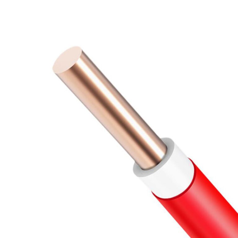
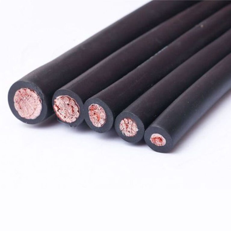
Unprotected cable fails quietly — a nick from a forklift, a stress fracture where a conduit edge wasn’t deburred, groundwater pooling in a trench that looked dry in August. The fault doesn’t always trip a breaker immediately; sometimes it degrades over months until a production line goes dark at the worst possible moment, and by then you’re looking at not just the cable replacement cost but lost throughput, an emergency procurement premium, and a contractor working overtime on a Saturday. That’s the problem armored cable exists to solve, and it’s worth understanding precisely where and why it earns its place in the design.
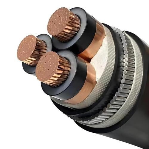
Armored cable is a power or signal cable reinforced with a protective mechanical layer — typically steel wire (SWA), steel tape, or aluminum wire armor (AWA) — that resists crush loads, rodent damage, accidental dig-through, and tensile stress during pulling or vertical installation. It is used wherever cables run through harsh environments: direct-buried utility runs, industrial plant floors, oil and gas facilities, mining operations, renewable energy installations, and any location where physical protection would otherwise require a separate conduit system.
What gets interesting is how much variation sits inside that definition. A 0.6/1 kV SWA cable feeding a pump motor on a factory floor and a 33 kV armored feeder running through a substation yard are technically the same category of product, but their specification, installation method, and failure modes have almost nothing in common. The right answer to “what is armored cable used for” depends heavily on which armored cable you’re talking about — and most specification mistakes happen because engineers treat the category as uniform when it isn’t.
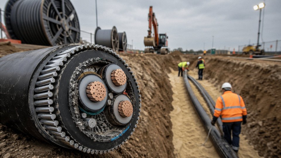
Steel Wire Armor vs. Steel Tape Armor vs. Aluminum Wire Armor — Choosing the Right Armor Type for Your Application
Pick the wrong armor type and you’re not just over-specifying — you’re potentially looking at sheath voltage hazards, premature jacket failure, or a cable that physically can’t handle the tensile load of a 40-meter vertical riser. These are not theoretical failure modes. They show up on real commissioning punch lists.
Steel Wire Armor (SWA): The Workhorse for Burial and Tensile Loads
SWA uses individually drawn galvanized steel wires laid helically over an extruded bedding layer. That helical lay is what gives it genuine tensile capability — typically 3–5 kN for medium-conductor cables in the 16–95 mm² range, though the actual figure depends on wire diameter, number of wires, and conductor count. For direct burial in rocky or aggressive backfill, SWA is usually the right call. The interlocked wire structure resists point loading from stones in a way that steel tape simply doesn’t.
Vertical riser installations — think a cable running from a basement switchroom up through multiple floor penetrations — demand SWA almost by default. The armor carries a share of the cable’s own suspended weight, preventing elongation of the conductor and bedding layers over time. Weight penalty is real: expect roughly 30–50% over an equivalent unarmored cable, depending on conductor cross-section and number of cores. That matters when you’re specifying cable tray load capacity or calculating seismic restraint requirements.
Steel Tape Armor (STA): Crush Protection Without the Weight
STA applies two thin steel tapes helically in opposing directions, overlapping so there’s no gap in coverage. It resists radial crush well — rated performance is broadly in the 4,000–6,000 N per 100 mm range depending on tape thickness — but it offers essentially no tensile strength. Pull an STA cable vertically under load and the tapes can separate.
Where STA earns its place is in horizontal duct banks, conduit runs, and multicore instrumentation or control cable installations where the mechanical threat is crushing from backfill compaction or conduit collapse, not tensile stress. It’s also easier to terminate cleanly, which matters on dense instrumentation marshalling racks where you’re making dozens of joints in a confined space. Lighter than SWA, easier to bend around tight radius corners — practical advantages that add up on a large control-building installation.
Aluminum Wire Armor (AWA): The Single-Core Imperative
This is where engineers occasionally get burned. Steel is ferromagnetic. On single-core AC cables, a closed magnetic steel armor forms a shorted turn around an alternating magnetic field, inducing circulating currents in the armor itself. Above roughly 70 mm² conductor cross-section, those eddy-current losses generate enough heat to degrade the outer sheath and, depending on bonding arrangement, create dangerous sheath voltages.
AWA replaces the steel wires with aluminum. Aluminum is non-magnetic, so the circulating-current problem disappears. For three-core cables, the opposing magnetic fields from the three phases largely cancel, so SWA remains acceptable — but on any single-core cable feeding a large motor or transformer, AWA is not a preference, it’s a technical requirement. Some specifiers use SWA with single-point bonding as an alternative, but that approach requires careful earthing design and isn’t always accepted by local utility standards.
Double-Wire Armor (DWA): When Torsion Enters the Picture
DWA layers two wire-armor constructions wound in opposite directions. The opposing lays resist both tensile pull and torsional twist — the kind of combined loading that occurs on submarine cable sections, offshore platform risers, or deep-pit mining feeders where the cable hangs freely and can rotate under tension. It’s heavier and more expensive than standard SWA, and it’s rarely needed in conventional land installations. Specifying DWA for a buried industrial feeder is over-engineering that wastes budget without adding useful service life.
Comparative Reference Table
| Armor Type | Typical Crush Rating | Tensile Rating | Weight Adder vs. Unarmored | Voltage Range | Best-Fit Environment |
|---|---|---|---|---|---|
| SWA | 4,000–6,000 N/100 mm | 3–5 kN (medium cores) | +30–50% | 0.6/1 kV – 33 kV | Direct burial, vertical risers, rocky ground |
| STA | 4,000–5,500 N/100 mm | Negligible | +15–25% | 0.6/1 kV – 11 kV | Horizontal ducts, conduit, control/instrumentation |
| AWA | 3,500–5,000 N/100 mm | 2–4 kN | +20–35% | 0.6/1 kV – 33 kV | Single-core power cables, non-magnetic requirement |
| DWA | 5,000–7,000 N/100 mm | 6–12 kN | +55–80% | 3.3 kV – 33 kV | Submarine, offshore risers, deep-shaft mining |
Ratings vary with wire diameter, core count, and conductor size. Treat these as specification starting points, not substitutes for the manufacturer’s technical datasheet.
Standards and Export Flexibility
IEC 60502-1 and IEC 60502-2 are the baseline references for SWA and AWA construction and testing in most international project specifications. BS 5467 and BS 6346 remain the dominant standards in Middle East, South Asia, and sub-Saharan Africa markets — the legacy of British electrical infrastructure investment in those regions runs deep, and many local utilities still specify BS explicitly in their tender documents.
Jinda armored cables are certified to both IEC 60502 and BS 5467/BS 6346 frameworks.True
Dual certification matters for export-oriented procurement: a cable manufactured only to IEC may be rejected by a Gulf utility requiring BS compliance, creating costly substitution delays mid-project.
Having both certifications on a single product line eliminates that substitution risk, which on a large substation project can mean the difference between on-time energization and a six-week procurement delay.
Underground Power Distribution — The Most Common and Demanding Use Case for Armored Cable
Direct burial is where armored cable earns its keep. No other installation method exposes cable to as many simultaneous threats — mechanical strike, soil chemistry, moisture ingress, thermal stress, and load cycling over decades — and no other application better illustrates why the armor layer is an engineering decision rather than a product upgrade.
Why Direct Burial Favors SWA Over Ducted Unarmored Cable
The practical economics are straightforward, even if the installation details are not. A direct-buried SWA cable eliminates the concrete protective slab that unarmored cable in a trench typically requires, and it allows narrower trench profiles — usually 200–300 mm wide for a single three-core run versus 400 mm or more when duct spacers and haunching are accounted for. In urban streetworks, trench width directly affects reinstatement cost and traffic disruption duration, so the savings compound.
More importantly, accidental strike protection matters in the real world. Ground-working machinery — a mini-excavator, a utility auger, even aggressive hand-digging — will occasionally contact buried services regardless of route marking. A well-spec’d SWA cable with rated crush resistance in the 4,000–6,000 N per 100 mm range (the upper end of that range coming from double-wire armor configurations) can survive a glancing strike that would sever an unarmored cable outright. That margin does not prevent all damage, but it frequently converts a catastrophic fault into a visible sheath abrasion that a patrolling crew can identify and repair before flashover.
Soil Classification Drives Sheath and Armor Selection
Not all ground is equal, and getting the sheath material wrong is an expensive mistake that usually only becomes obvious two or three years into service.
Rocky soil and urban backfill containing sharp aggregate, broken masonry, or compacted hardcore demand SWA — the wire armor distributes point loads rather than concentrating them on the sheath. Clay-rich soils present a different problem: clay retains moisture well, which helps thermally, but clay often correlates with elevated sulfate concentrations and occasionally with low pH. Where soil pH drops below roughly 5.5, or where sulfate levels are elevated (common near certain industrial sites, disturbed brownfield ground, or coastal reclaimed land), a standard PVC outer sheath will degrade noticeably within five to ten years. HDPE or medium-density polyethylene outer sheaths resist chemical attack far better and are the correct choice in those conditions — not an optional upgrade.
Polyethylene outer sheaths provide significantly better resistance to soil chemical attack than standard PVC sheaths in acidic or high-sulfate ground conditions.True
PVC plasticizers leach in chemically aggressive soils and the compound softens and cracks over time; PE and HDPE are non-polar polymers with inherently low reactivity to acids and sulfates, making them the standard specification for chemically aggressive burial environments per IEC and BS installation guidance.
Burial Depth, Codes, and Why Armor Fills the Gap
IEC 60364-5-52 and most national grid codes set minimum burial depths at around 0.5 m for LV cables in pedestrian zones, stepping up to 0.8–1.0 m for MV runs and 1.0–1.2 m in vehicle-trafficked areas. In practice, those depths are not always achieved — ground obstructions, existing services, and contractor shortcuts mean actual depth varies along any given route. Armor provides the residual safety margin when installation geometry is imperfect, which in real projects it often is.
Thermal Derating Is Where Engineers Lose Current Capacity
Soil thermal resistivity typically falls between 0.7 and 2.5 K·m/W, and that range is almost entirely governed by moisture content. Dry, sandy soil in an arid climate is near the top of that range; damp, loamy soil sits toward the bottom. The difference matters significantly for current-carrying capacity.
A 95 mm² three-core SWA XLPE cable rated at roughly 225–235 A in free air at 30 °C ambient can derate to approximately 155–170 A when direct-buried at 1.0 m depth in dry soil with a thermal resistivity around 2.0–2.5 K·m/W. That is a 25–30% reduction — enough to push an undersized design into overload during peak summer loading. Engineers who specify cable based on free-air ratings and apply a single generic correction factor frequently undersize underground circuits, and the fault usually appears as unexplained tripping or accelerated insulation degradation rather than an obvious overload event.
Route Documentation and Marker Systems
Utilities and municipalities increasingly require formal route documentation as a project handover deliverable — GPS-referenced route files, as-built drawings with depth confirmation at regular intervals, and physical marker systems including warning tiles laid 150–200 mm above the cable and above-grade route markers at bends, joints, and service entry points. This is not bureaucratic overhead. It directly reduces the probability of third-party strike during future groundworks, and infrastructure owners who skip it typically pay for it during the next road resurfacing or utility upgrade cycle in the same corridor.
Procurement Considerations for Long-Term Underground Projects
For utility grid upgrade programs — the kind of multi-year, multi-lot projects common in Southeast Asia, Sub-Saharan Africa, and the Middle East right now — supply consistency matters as much as specification compliance. Armor lay length, sheath thickness tolerances, and drum length scheduling all affect installation productivity on large jobs. Jinda’s SWA and XLPE armored underground distribution cables have been supplied into utility grid upgrade projects across these regions, and procurement teams evaluating a long-term partner should be asking about production scheduling flexibility and third-party type test documentation alongside unit pricing. A supplier who can deliver consistent drum lengths on a rolling call-off contract is worth considerably more than the cheapest landed price on a one-shot purchase.
Industrial Facilities: Petrochemical Plants, Mining Operations, and Heavy Manufacturing Where Armored Cable Is Non-Negotiable
Standard cable fails quietly in industrial environments. The insulation degrades from chemical exposure, a forklift clips the tray, a trailing cable gets pinched under a loader — and you’re looking at either an unplanned outage or, in the wrong atmosphere, something considerably worse. Armored cable in these settings isn’t a specification upgrade; it’s the baseline.
Petrochemical Plants and Refineries
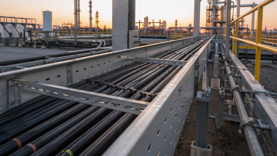
Process plant cable trays are arguably the most demanding routing environment outside of a mine. You have mechanical hazard from maintenance traffic, thermal cycling, and — critically — the fire scenario. If a hydrocarbon fire breaks out, cables that generate heavy smoke or release halogen acids can incapacitate personnel trying to evacuate or respond. That’s why SWA with LSZH outer sheath has become the dominant specification on most new process plant projects, and why cable procurement managers on these sites will ask for IEC 60332-3 flame-spread test compliance almost reflexively.
IEC 60332-3 covers flame propagation along cable bundles — the real risk when you have cable trays stacked three or four layers deep. IEC 60331 goes further, requiring the cable to maintain circuit integrity under fire at 750–840°C for a defined period, typically 90 or 180 minutes depending on the safety function. Emergency shutdown systems, fire pump feeders, and ESD valve actuators all need IEC 60331-rated cables. Specifying IEC 60332-3 alone on those circuits is a common and expensive mistake.
Underground and Open-Pit Mining
Mining cables live a genuinely brutal life. A rubber-insulated, steel-wire armored trailing cable on a continuous miner or a longwall shearer flexes thousands of times per shift, drags across abrasive rock surfaces, and gets run over by machinery that weighs tens of thousands of kilograms. The expected service life on a well-specified mining trailing cable runs 15–20 years, but that figure depends entirely on the armor design and the flexibility class of the core construction.
IEC 60502 and IEC 62440 set the framework for mining cable designs, covering everything from insulation compound requirements to the minimum bend radius under dynamic load. The armor on a trailing cable isn’t the rigid SWA you’d use in a fixed installation — it’s a flexible steel wire braid or helical construction that allows the cable to coil and straighten repeatedly without fatiguing the wires. Ore dust and rock particulates act as an abrasive over time, so sheath hardness matters almost as much as the armor itself. In my experience, sites that skip on sheath compound quality to save a few percent on cable cost end up replacing trailing cables at roughly twice the frequency.
Steel Mills, Cement Plants, and Foundries
Ambient temperatures near furnace areas or kiln drives routinely run 50–80°C, sometimes higher in confined routing ducts. PVC insulation starts to soften and lose dielectric strength above roughly 70°C; XLPE handles continuous operation up to 90°C conductor temperature, and EPR performs reliably in wet or thermally aggressive environments where XLPE would be marginal. SWA over XLPE or EPR is the standard answer for these locations — mechanical protection against crane operations and forklift traffic, combined with insulation that isn’t quietly degrading from heat.
Thermal derating here isn’t optional arithmetic. If your cable carries 80% of its rated current and the ambient is already 70°C, you may have almost no derating margin left. That’s a conversation worth having with your cable supplier before the tray layout is finalized.
Hazardous Area Wiring — ATEX and IECEx Zones
Armored cable simplifies hazardous area installations in a practical way that conduit systems don’t. Each conduit joint, seal fitting, and termination is a potential ignition risk point that must be maintained and inspected. A properly terminated armored cable with A2- or E1W-certified explosion-proof glands reduces that count significantly. The armor itself functions as a grounded mechanical barrier — important both for ignition risk control and for fault current return path integrity.
Gland selection is where most installation errors happen on ATEX/IECEx jobs. The gland must physically clamp the armor wires or tape, not just grip the outer sheath, or the explosion protection integrity is compromised regardless of what the cable certificate says. This is worth flagging to installation contractors explicitly; it gets missed more often than it should.
Vibration Environments
Pump houses and compressor stations present a different problem. Cables routed close to reciprocating or rotating machinery experience continuous micro-bending. Over months, that fatigues the conductor stranding and can crack the insulation at support points. SWA provides enough stiffness along the cable run to damp vibration transmission, and proper cleat spacing — typically every 300–500 mm in high-vibration areas depending on cable diameter and machinery frequency — does the rest. Flexible conduit between the tray and the motor terminal box is still needed for the final connection; SWA is not a substitute for that.
IEC 60331-rated fire-resistant armored cables maintain circuit integrity under fire conditions at temperatures up to 840°C for the rated duration.True
IEC 60331-11 and related parts specify test temperatures of 750°C to 840°C depending on the test method, with circuit integrity maintained for durations of 30, 90, or 180 minutes as specified in the cable rating.
Jinda’s industrial product range covers fire-resistant armored cables to IEC 60331, LSZH-armored cables to IEC 60332-3, and mining-rated armored flexible cables with rubber insulation systems suited to the trailing cable duty cycle. For projects with non-standard requirements — whether that’s a sheath compound resistant to specific chemicals at elevated temperature, or a customized flexibility class for an unusual application — the R&D team can work from the operating environment parameters rather than forcing the project into a catalog item.
Renewable Energy Infrastructure: Solar Farms, Wind Farms, and Battery Storage Systems Driving New Armored Cable Demand
The renewable energy build-out has quietly become one of the most technically demanding environments for armored cable specification — arguably more varied in its requirements than conventional utility distribution, because you’re dealing with DC systems, marine environments, agricultural terrain, and grid-scale battery installations all within the same project category. Each sub-application has its own failure modes, and specifying a generic armored cable across all of them is how projects end up with premature insulation failure or corrosion-related outages five years into a twenty-five-year asset life.
Utility-Scale Solar: DC Collection Cables Across Hundreds of Hectares
Large photovoltaic farms present a straightforward but underappreciated logistics problem: running DC collection cables from string combiner boxes back to central inverters across land that may span 200–600 hectares. Trenching and installing conduit across that area adds meaningful cost per meter — enough that many EPC contractors now specify direct-buried DC armored cable instead, particularly where soil conditions allow. The relevant standard is IEC 62930, which covers DC cables rated at 1.5 kV or 1.8 kV with UV-resistant outer sheaths, and SWA is the typical armor choice here since the mechanical threat is primarily crush and rodent damage rather than tensile load.
One practical consideration that catches people out: UV degradation at above-ground transition points — where cable exits the trench to connect at the combiner box or inverter skid — requires a sheath compound that handles both burial conditions and direct sun exposure. Specifying the wrong outer sheath material here leads to surface cracking within three to four years in high-UV climates, particularly in Middle Eastern or Australian sites.
Wind Farm Inter-Array Cables: Ground Settlement and Waterlogging
Inter-turbine array cables run underground between turbine foundations, often crossing agricultural land or coastal terrain where soil conditions are variable. The standard inter-array voltage in most markets has converged on 33 kV, with SWA XLPE cables to IEC 60502-2 being the workhorse specification. What makes this application harder than a straight utility burial is the dynamic loading near turbine foundations: ground settlement and minor movement over the first few years can impose bending stress on cables that a simple point-load crush test doesn’t capture. Coastal soils, particularly in tidal or estuarine zones, add intermittent waterlogging and elevated chloride content, which accelerates corrosion of unprotected steel armor — proper galvanizing specification and a tight outer sheath are not optional here.
Offshore Wind: The Most Demanding Armor Requirement in Any Sector
Offshore inter-array and export cables represent the top end of armored cable engineering. During installation from a cable-lay vessel, the cable must survive tensile loads during dynamic laying operations while still being flexible enough to spool off the vessel’s turntable. Once on the seabed, the threats shift to abrasion against rock or shell substrate, tidal scour, and — at shallower inshore sections — the real risk of anchor strike. Double-wire armor (DWA) addresses both the installation tensile requirement and long-term seabed protection; no other armor configuration reliably handles both simultaneously. Outer sheaths are high-density polyethylene (HDPE or PE) as standard, since PVC degrades in seawater over the service life spans involved, which typically run 25–30 years.
Double-wire armor (DWA) is the industry-standard armor configuration for offshore wind submarine cables due to its combination of tensile strength during cable laying and mechanical protection against seabed abrasion over a 25-year service life.True
DWA is specified in IEC 60502-4 and related offshore cable standards specifically because single-wire armor lacks sufficient tensile capacity for deepwater dynamic laying operations, and steel tape armor provides no meaningful tensile protection at all. The 25-year design life is the standard minimum for offshore wind assets under IEC and most national grid interconnection requirements.
Battery Energy Storage Systems: Fault Current and Confined-Space Mechanical Protection Together
Grid-scale BESS installations introduce a specification combination you don’t often see elsewhere: the cable needs to handle DC fault currents that can be substantially higher than steady-state ratings (battery arrays can dump fault energy very quickly), while also being mechanically robust in confined battery enclosures where installation tolerances are tight and cable movement during maintenance is inevitable. SWA armored DC cables rated for the relevant voltage class provide the armor needed to prevent insulation damage in dense cable tray arrangements, while also offering a defined fault current path if the armor is properly earthed — which in a DC system requires deliberate design attention, not an afterthought.
High-Voltage Export Cables: The Fastest-Growing Segment
Export cables connecting offshore or remote renewable sites to grid substations — typically 66 kV to 220 kV — are growing faster than almost any other cable category globally. At these voltage levels, armor specification intersects with sheath bonding design in ways that matter for efficiency: circulating currents in the armor of an improperly bonded single-core HV cable can account for 3–8% additional losses depending on cable length and current magnitude. That’s not trivial over a 25-year operating life. Cross-bonding or solid-bonding decisions need to be made at the design stage, not retrofitted.
Shandong Jinda supplies IEC 60502-2 certified medium-voltage SWA armored cables into wind and solar projects across Southeast Asia and the Middle East, with project-specific documentation packages covering test reports, material certificates, and factory acceptance testing — the kind of documentation that offshore and utility-scale projects require for grid connection approval and lender due diligence. Armored cable specifications for renewable projects are project-specific enough that early supplier engagement, before the EPC contractor finalizes the cable schedule, consistently produces better outcomes than treating cable as a late-stage procurement commodity.
Building and Construction Applications: Where Armored Cable Meets Electrical Codes and Fire Safety Regulations
Armored cable in buildings occupies a narrower, more regulated space than in underground or industrial work. The mechanical threat is usually lower — you’re not fighting rock fall or excavator buckets — but the fire safety and code compliance requirements become much stricter, and in some jurisdictions, getting the specification wrong means a failed inspection, a costly remediation, or worse, a circuit that drops out exactly when a building is on fire.
MICC vs. SWA: Two Armored Cable Families, Very Different Jobs
Mineral insulated copper-clad (MICC) cable and steel wire armored cable are both “armored” in the broad sense, but they solve different problems and should never be treated as interchangeable.
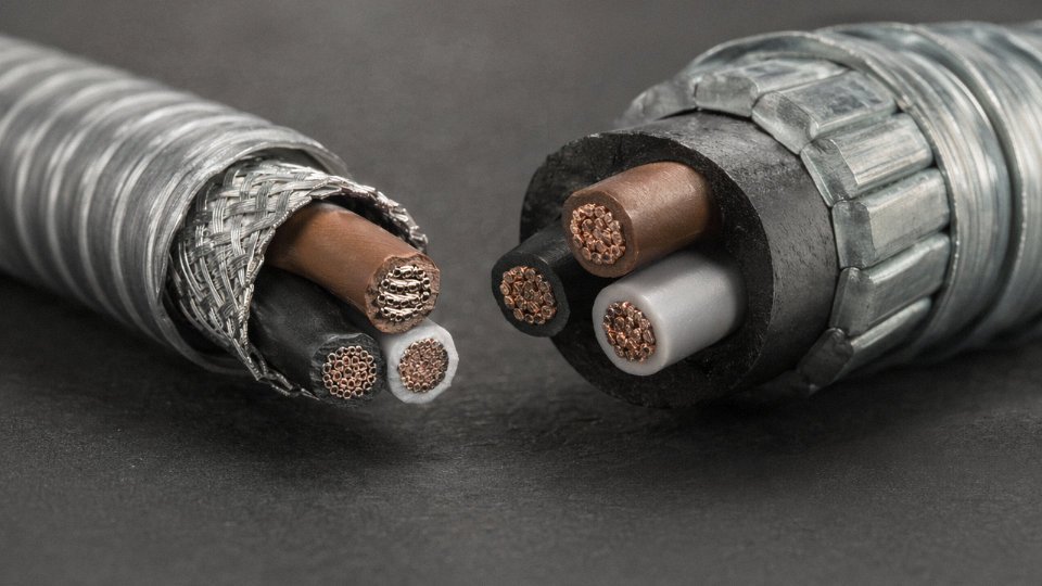
MICC uses compressed magnesium oxide insulation inside a seamless copper sheath. That construction gives it circuit integrity at temperatures up to 950°C under IEC 60331, which is why it’s the default specification for emergency lighting circuits, fire alarm wiring, and life-safety systems like smoke extract fans and sprinkler pump controls. No polymer-insulated cable — armored or not — gets close to that fire survival performance. The tradeoff is cost (MICC runs 3–6× the price of equivalent SWA per meter, depending on conductor size and market), difficult termination requiring specialist skills, and practically zero flexibility in tight conduit runs.
SWA, on the other hand, is the workhorse for general power distribution in industrial and commercial buildings: rising mains in multi-storey plant rooms, external routes between buildings, basement distribution boards, sub-main feeds to motor control centers. It handles mechanical abuse, rodents, and the casual damage that happens when a building is being serviced. For anything below about 33 kV in a commercial or industrial building, SWA with XLPE or PVC insulation covers the vast majority of applications.
Wiring Regulations and the Markets That Matter
IEC 60364 is the baseline framework most of the world works from, but regional adoption varies enough to trip up procurement teams sourcing cable for export projects.
UK projects follow BS 7671 18th Edition (the IET Wiring Regulations), which effectively mandates mechanical protection — armored cable or conduit — for cables in locations subject to mechanical damage: risers, external walls, underground routes within the curtilage of a building, and any run where cable could be struck during maintenance. The 18th Edition also tightened requirements around protective bonding, which has direct implications for how SWA armor is terminated and earthed (more on that below).
GCC markets — specifically projects under DEWA in Dubai and KAHRAMAA in Qatar — follow IEC-aligned national standards but layer on additional requirements: fire survival cable specifications for specific building occupancy types, mandatory use of low-smoke zero-halogen (LSZH) outer sheaths in occupied and escape route areas, and documentation trails demanding third-party test certificates. African markets following IEC-aligned national codes (South Africa’s SANS 10142 being the most structured) are broadly similar to IEC 60364 in armored cable requirements, though inspection capacity and enforcement vary considerably between countries.
Installation Labor and the Conduit Argument
In plant rooms and basement distribution areas, one of the most underappreciated advantages of SWA is the elimination of conduit. A conduit-and-wire system in a commercial plant room involves conduit sizing, pulling calculations, junction boxes, and inspection fittings. SWA runs directly on cable tray or ladder rack, terminated with standard Type A or Type E brass glands, into standard switchgear knockouts — no special tooling required.
Installing SWA cable on cable ladder in commercial plant rooms reduces installation labor by 20–35% compared to equivalent conduit-and-wire systemsTrue
This range is consistent with contractor estimates and site studies in commercial construction; the actual saving depends on run length, bend frequency, and conduit fill ratio — shorter, straighter runs favor conduit less; complex multi-cable routes favor SWA more significantly
In practice, on a medium-sized commercial project — say, a multi-floor office block with a basement plant room — the labor saving across the distribution board sub-mains alone can offset a meaningful portion of the cable cost premium over unarmored alternatives.
Fire-Resistant Armored Cable for Critical Buildings
Hospitals, airports, and data centers carry a combined specification burden: circuit integrity under fire (IEC 60331-21 for cables up to 20 mm overall diameter, IEC 60331-23 for larger sizes, both requiring 90 minutes minimum at 750°C), plus smoke and toxicity control. The standard answer is SWA construction with an LSZH outer sheath, IEC 60331-tested insulation system, and a flame retardant inner serving. Some specifiers also call for IEC 60332-3 bunch flame retardant performance where multiple cables share a route.
Don’t assume these requirements are automatically compatible. An SWA cable with a standard PVC outer sheath might pass IEC 60331 circuit integrity but fail the LSZH requirement. Always verify both certifications are present on the same cable construction — the test certificate should reference the actual cable type, not a generic family.
SWA Armor as a Protective Earth Conductor
This is worth flagging because engineers occasionally miss it, and it has real cost implications. In TN-C-S and TN-S supply systems, the steel wire armor of an SWA cable can legally serve as the circuit protective conductor (CPC), provided the armor is properly bonded at both ends and the armor resistance is verified to satisfy the earth fault loop impedance requirement under the relevant wiring regulations.
When it works — and it usually does for shorter runs on larger-gauge cables — you save a separate earth conductor, which on a 4-core XLPE/SWA cable means you’re effectively getting the CPC for free. On a large distribution project with dozens of sub-main runs, that copper saving is not trivial. The engineering check is straightforward: calculate armor resistance using manufacturer data (typically 0.5–2.5 Ω/km depending on armor wire size and configuration), verify the loop impedance against the disconnection time requirements, and document it. Skipping that verification is how you end up with a compliant-looking installation that fails a fault loop impedance test during commissioning.
Submarine, Marine, and Offshore Platform Wiring: Specialized Armored Cable Environments with Zero Fault Tolerance
Submarine and offshore wiring sits in a category of its own. The mechanical loads are severe, the electrochemical environment is hostile, access for repair is either expensive or impossible, and a single cable fault on an island interconnection or FPSO can knock out power to an entire facility for days. These are not applications where you specify a cable, install it, and revisit the decision in twenty years. You get one shot at the design.
Submarine Crossings: Lead Sheath, PE Outer Sheath, and Why Polymer Tape Alone Is Not Enough
River crossings, harbor installations, and short-sea island interconnections typically use single-core or three-core SWA cables built with a lead sheath directly over the insulation. The lead sheath is the critical element here — it provides a continuous radial water barrier that longitudinally applied polymer tapes simply cannot replicate reliably over a 30-to-40-year service life. Water vapor permeates through polymers slowly but persistently, especially at elevated operating temperatures. Lead, despite its cost and handling complications, doesn’t. Over the cable’s service life, even a small amount of moisture ingress into XLPE insulation will degrade partial discharge performance and eventually cause insulation breakdown.
The outer sheath is typically high-density PE rather than PVC, because PE resists abrasion from riverbed sediment and gravel significantly better, and its lower water absorption matters when the cable is sitting wet indefinitely. Galvanized steel wire armor — SWA — wraps the outside, providing both mechanical crush protection and, critically, tensile strength during and after laying.
Offshore Platforms and FPSOs: IEC 60092 Is the Baseline, Not a Suggestion
Platform and FPSO wiring operates under a completely different set of constraints compared to shore-based industrial cable. Cables are required to meet IEC 60092 (marine cables), and in practice most operators and EPC contractors demand third-party classification society approval — Lloyd’s Register, DNV, Bureau Veritas, or equivalent — before a reel ever boards a vessel. That approval process involves factory audits, material traceability documentation, and witnessed type testing, not just a certificate number.
The armor on a marine cable must handle continuous vibration from hull motion, compressor operation, and wave loading simultaneously, for years. Salt spray attacks ungalvanized steel aggressively; the coating spec on the armor wires matters more than most procurement teams realize. Hydrocarbon atmospheres on process decks add the further requirement for flame-retardant outer sheath compounds — halogen-free, low-smoke formulations are now the norm on modern offshore projects.
Deep Water: Hydrostatic Pressure and Water Migration
Below roughly 200 m, hydrostatic pressure becomes a cable design parameter rather than a background condition. At that pressure, water can be driven along conductor interstices — the small air gaps between stranded conductors — progressively migrating toward joints and terminations. Water-blocking tape applied longitudinally under the armor, combined with moisture-barrier sheaths, is mandatory construction for any deep-water cable. Double-wire armor (DWA), with two counter-wound layers of steel wire, resists radial deformation from external pressure better than a single-wire design and is standard for depths beyond 200–300 m, depending on cable diameter.
Cathodic Protection and Galvanic Corrosion: The Grounding Detail That Destroys Cables
Steel armor immersed in seawater participates in the electrochemical environment whether you intend it to or not. Grounding armor at both ends in a saltwater installation creates a galvanic cell — the armor acts as an anode in certain soil or seawater conditions, and corrosion can strip the wire cross-section noticeably within a few years. Standard practice is single-end bonding, with the remote end isolated, or sacrificial anode protection for longer sections. This is a detail that gets missed on short harbor crossings specified by engineers more familiar with land-based LV distribution than marine work. The consequence is not immediately visible; it shows up as a snapped armor wire under tensile load during an inspection five years post-installation.
Installation Tension: A Structural Parameter, Not an Afterthought
Submarine cables experience tensile loads ranging from roughly 10 kN on shallow-water, short crossings to well over 100 kN on deep-water installations, depending on water depth, cable weight per meter, and laying vessel catenary geometry. The armor wire layer carries that load — the conductor and insulation do not contribute meaningfully to tensile strength. Manufacturers must provide certified tensile test data as part of the factory acceptance test (FAT) package. Specifying a cable without requesting FAT tensile results and reviewing them against the installation load calculation is a procurement gap that has caused cable failures during the laying operation itself, which is about the worst possible time.
Lead sheath submarine cables provide superior long-term radial water barrier performance compared to polymer tape-only designs for cables with service lives exceeding 25 years in submerged installations.True
Lead's near-zero moisture vapor transmission rate versus XLPE-compatible polymer tapes is established in IEC and CIGRE submarine cable design guidance; long-term performance data from interconnection projects consistently supports lead sheath construction for permanent submerged applications.
Jinda manufactures IEC 60092-compliant armored marine cables with classification society certification support, serving port infrastructure, island electrification programs, and offshore projects across Southeast Asia, West Africa, and the Middle East Gulf region. For export projects requiring FAT documentation, third-party witness testing, and full material traceability, Jinda’s five production bases and integrated QC system are built to support those requirements directly rather than through intermediaries.
Installation Best Practices: Bending Radius, Gland Selection, Earthing, and Avoiding the Most Costly Mistakes
Getting the cable specification right is only half the job. A correctly specified SWA cable can still fail within months if installation is rushed or shortcuts are taken on glands, earthing, or drum handling — and in my experience, the most expensive failures trace back not to the cable itself but to decisions made on the day of laying.
Minimum Bending Radius: The Rule That Gets Ignored Until Something Birdcages
IEC 60502 sets minimum installation bending radii at 6×D for multicore SWA cables and 8×D for single-core, where D is the overall cable diameter. These aren’t conservative padding — they reflect the mechanics of how steel wires behave under bending stress. Pull a 50 mm overall-diameter multicore around a 200 mm radius bend and you’ve already violated the limit by half. What happens next is called birdcaging: individual armor wires flare outward at the over-bent section, creating a stress concentration that works against the conductor insulation with every thermal cycle afterward. The cable may pass initial continuity testing and still fail at that point eighteen months later. Once birdcaging occurs, the armor geometry is permanently distorted and the installation warranty is void. During cable pulling through conduit or duct bends, it’s worth calculating the actual bend radii at every change of direction before the drum is even moved into position.
Gland Selection: Two-Part Design, Correct Type, Correctly Torqued
This is probably the most underspecified item on installation BOMs. A two-part SWA cable gland — type A2 for indoor or protected locations, E1W for outdoor and wet environments per BS 6121 classification — works by clamping the armor wires between an inner cone and an outer lockring. That clamping action does two things simultaneously: mechanical retention (the cable can’t pull back through the gland) and electrical continuity of the armor earth path. Use a single-part compression gland, or forget to fully tighten the lockring, and neither function is properly achieved. Incorrect gland selection is consistently among the top three causes of premature armored cable failure in field installations — the armor earth path becomes intermittent, earth fault protection becomes unreliable, and the mechanical anchor works loose under cable movement.
Incorrect cable gland selection is one of the leading causes of armored cable premature failure in field installations.True
Field failure analysis data from cable contractors and electrical testing bodies consistently identifies improper gland type or incorrect installation torque as a primary failure mechanism for armored cable terminations, compromising both mechanical retention and the armor earth continuity path.
Armor Earthing: Single-End vs. Both-Ends Bonding Matters More on Large Cables
For three-core SWA cables, both-ends bonding is standard practice and gives the lowest earth fault loop impedance — straightforward. Single-core cables above roughly 150 mm² are a different story. Bonding armor at both ends creates a complete circuit for induced currents, and on large single-core cables those circulating currents can generate enough heat to derate the cable significantly, or in extreme cases damage sheath insulation. Single-end bonding with surge voltage limiters fitted at the unearthed end breaks the circulating current path while still clamping transient overvoltages. The crossover point varies with cable length, current magnitude, and installation arrangement, so it’s worth doing the circulating current calculation rather than defaulting to both-ends bonding on every run.
Pulling Tension and Conductor Protection
Maximum pulling tension limits are 50 N/mm² on copper conductors and 30 N/mm² on aluminum. Aluminum yields at a lower stress threshold, and plastic deformation in the conductor is invisible during inspection but causes long-term resistance hot spots. Always attach pulling socks to the armor, not the conductor, during direct-burial pulls. Conductor grips used on the conductor ends concentrate stress exactly where you don’t want it.
Cold-Weather Installation and Drum Storage
PVC-sheathed armored cable should not be installed at ambient temperatures below 0°C without pre-conditioning — typically 24 hours stored above 10°C. Cold PVC turns brittle enough that normal installation handling causes outer sheath cracking, exposing the armor to corrosion from the first day of service. This is easy to overlook in winter site schedules when there’s pressure to hit commissioning dates.
Drums must be stored upright on their flanges. Flat storage compresses the lower cable layers under the combined weight of drum and cable, distorting armor wire geometry in ways that aren’t always obvious until the cable is unspooled. Store drums off bare ground on bearers, covered to prevent moisture tracking in through drum end-boards.
How to Read an Armored Cable Specification and Order Correctly — A Procurement Reference Guide
Getting the specification right before the purchase order is raised is where most project engineering effort should go. A mis-specified armored cable that reaches site and fails acceptance testing costs far more than the cable itself — you’re looking at demobilization, re-pull, extended commissioning, and in some cases liquidated damages. This section is a working reference, not a glossary.
Decoding the Cable Designation Code
Take a typical designation you’ll see on a project drawing or datasheet:
3×95+50 mm² 0.6/1 kV XLPE/PVC SWA PVC
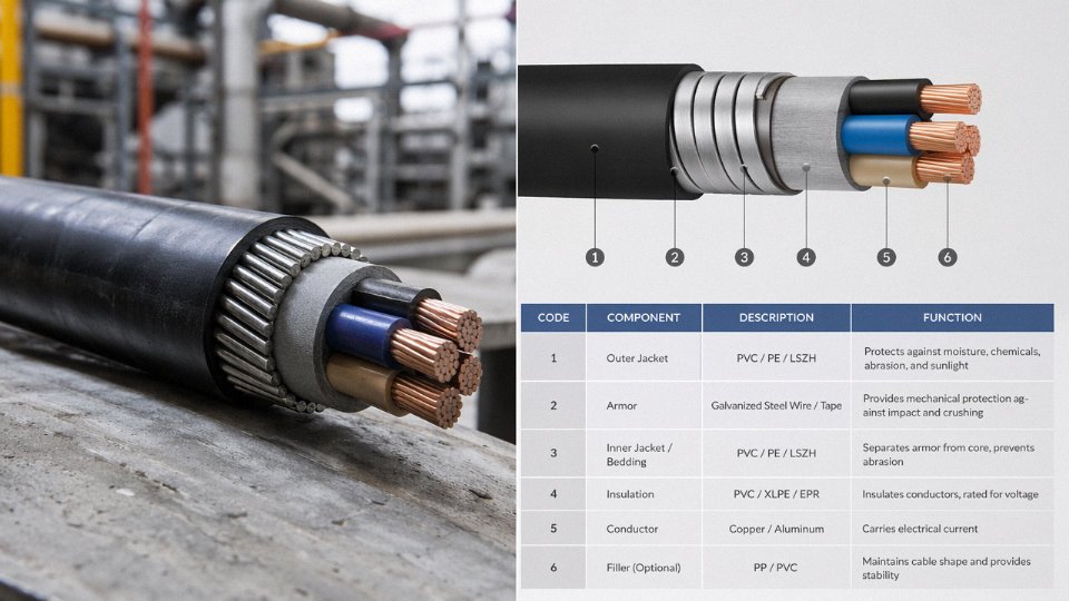
Reading left to right: 3 is the number of power-carrying conductors. 95 mm² is the cross-sectional area of each power core. The +50 mm² is the combined earth or neutral conductor — sized separately because its fault current duty differs from the line conductors. 0.6/1 kV is the voltage class (conductor-to-earth / conductor-to-conductor, with the Um, the maximum system voltage, usually stated in the full IEC designation). XLPE identifies the conductor insulation; PVC is the inner bedding over the laid-up cores. SWA is steel wire armor. The final PVC is the outer sheath.
Every element in that string maps to a physical layer and a performance requirement. Drop one symbol and a supplier in a different country may substitute silently — aluminum wire armor instead of steel, for instance, or a PVC sheath rated to 70°C instead of 90°C. That substitution changes your fault current capacity, your bending radius limits, and potentially your fire compliance.
The Procurement Specification Checklist
A complete cable order should lock down: voltage class (Uo/U, and Um if relevant), number and cross-section of power cores, earth/neutral conductor size and whether it’s a separate core or concentric, conductor material (copper or aluminum — aluminum is meaningfully cheaper but requires larger cross-sections and different termination hardware), insulation type (PVC, XLPE, or EPR for higher operating temperatures), armor type (SWA, AWA, STA, or double wire armor for severe crush or tensile applications), outer sheath compound (standard PVC, LSZH for enclosed spaces, UV-stabilized PE for surface runs in direct sunlight, HDPE for aggressive chemical environments), and the governing standard — IEC 60502-1 or -2, BS 5467, AS/NZS 1429, or others as required by the project specification or the authority having jurisdiction.
Special requirements — fire resistance per IEC 60331, enhanced circuit integrity, low smoke per IEC 61034 — must be stated explicitly. They are not implied by LSZH sheath selection alone.
Conductor Sizing: The Fault Current Point Most Buyers Miss
The armor contributes to fault current carrying capacity, but it does not carry rated load current. Your power core cross-section must be sized for both continuous load current (using the appropriate derating for burial depth, grouping, and soil thermal resistivity) and for short-circuit fault current, typically calculated for a 1-second or 3-second fault clearance time per IEC 60909. Undersizing the conductor cross-section to save cable cost and relying on the armor to handle fault energy is a calculation error with real consequences — insulation damage, possible fire, and almost certain warranty dispute.
Armored cable conductor cross-section must be independently sized for both load current and short-circuit fault current; the armor layer does not substitute for adequate conductor sizing.True
Per IEC 60909 and IEC 60502, armor contributes to earth fault current return path impedance but the current-carrying conductors must be rated for both thermal steady-state loading and adiabatic short-circuit heating independently.
Test and Certification Documentation
For any international supply, expect and request: routine test certificates issued per IEC 60502-1 Clause 17 covering conductor resistance, high-voltage test, and insulation resistance; type test reports (these confirm the design, not the specific drum); third-party certification from recognized bodies such as KEMA, CESI, or SGS; certificate of origin (often required for customs clearance and preferential tariff eligibility); material safety data sheets for the sheath compound, particularly if LSZH; and a factory acceptance test protocol if your project requires witnessed testing before shipment. Asking for these upfront, before production starts, avoids the common situation where a supplier ships first and scrambles for paperwork afterward.
Drum Length and Joint Planning
Standard production drum lengths for armored cables run roughly 500 m for larger conductor sizes (240 mm² and above) up to around 2,000 m for smaller distribution cables — the actual length depends on conductor cross-section, armor weight, and drum capacity. On a long continuous cable route, any drum boundary means a joint, and joints are the most vulnerable points in a buried system. Where a project demands unjointed runs beyond standard drum capacity, it’s worth discussing extended continuous length production with your supplier early — not every manufacturer can accommodate this, and the lead time implication is real.
Why IEC Rather Than a Proprietary National Standard
IEC 60502 is recognized across more than 100 countries, which matters practically when a cable is manufactured in one country, shipped through another, and installed in a third. Customs documentation, project audits, and third-party inspection are all simpler when the governing standard is universally understood. Dual certification to both IEC 60502 and BS 5467 means a single supplier can serve both IEC-standard markets and legacy BS-standard projects — common in the Middle East, parts of Africa, and certain Southeast Asian markets — without requiring reformulation or separate type testing. That flexibility reduces procurement complexity on multi-country infrastructure programs more than most buyers realize until they’re mid-project.
Frequently Asked Questions About Armored Cable Use, Selection, and Installation
These are the questions that come up repeatedly — from site engineers who’ve just received a delivery and aren’t sure how to terminate it, to procurement managers trying to evaluate competing bids. Answers below are based on what actually matters in practice.
Can armored cable be used outdoors above ground?
Yes, but with a critical qualifier: the outer sheath material determines whether it survives. SWA and AWA cables manufactured with a UV-stabilized PE or HDPE outer sheath are fully suitable for outdoor aerial runs, surface conduit mounting, or direct cable tray exposure. Standard PVC outer sheath is a different story — it is not UV-stabilized, and in direct sunlight you’ll typically see visible surface cracking within 2–5 years, faster in tropical or high-UV environments. The armor itself doesn’t protect against UV degradation; it protects against mechanical damage. Always confirm the outer sheath compound code on the drum label before specifying an outdoor run. If the data sheet just says “PVC outer sheath” without a UV-stabilized grade, assume it’s not rated for sustained outdoor exposure.
Is armored cable waterproof?
The armor layer is not a water barrier — full stop. Moisture resistance depends entirely on the outer sheath and, where required, additional water-blocking layers beneath it. PE outer sheath outperforms PVC on moisture resistance across long burial periods. For cables that will be permanently submerged — a river crossing, a flooded cable pit, a coastal trench with tidal ingress — you need to specify a water-blocking design explicitly. That means longitudinal water-blocking tape, swellable powder filling, or in the most demanding cases, a lead sheath beneath the armor. The words “waterproof” and “submersible” are not automatically implied by “armored cable.” Get the design confirmed in writing in the technical schedule.
Can you cut armored cable with a standard cable cutter?
The outer sheath and insulation cut fine with ordinary tools. The armor is the problem. Steel wire armor requires either a rotary armored cable stripper, a purpose-built armored cable cutter (Ripley and similar brands make these), or an angle grinder with a cutting disc on larger conductor sizes. If you try to cut SWA with side-cutters or a standard knife, you risk burring or splaying the armor wires, which then punch through the underlying bedding layer and damage the insulation. That’s not a hypothetical — it’s a reasonably common cause of failed terminations on site. Aluminum wire armor is softer and easier to cut, but the same principle applies: use the right tool.
What is the difference between armored cable and mineral insulated cable (MICC)?
Armored cable uses polymer insulation — PVC or XLPE — with a mechanical steel or aluminum armor layer over it. MICC is a fundamentally different construction: compressed magnesium oxide insulation inside a seamless copper or stainless steel tube, with no polymer in the primary insulation at all. In fire conditions, MICC maintains circuit integrity to around 950°C; fire-resistant armored cable (with mica tape insulation under an XLPE or PVC jacket) typically provides circuit integrity to 750–850°C, depending on design. MICC is more expensive, considerably less flexible, and harder to terminate correctly — a poorly made MICC termination absorbs atmospheric moisture into the MgO and fails. It has genuine niches: emergency lighting circuits inside plant rooms, stairwell pressurization fans, fire pump wiring in buildings where insurance or code demands the highest available fire rating. For most industrial runs where fire resistance is required but not to MICC levels, fire-resistant SWA cable is the practical and economical answer.
Does the SWA armor count as an earth conductor?
Under BS 7671 and IEC 60364, the steel wire armor can serve as the circuit protective conductor — but only if the armor’s cross-sectional area satisfies the adiabatic equation for the overcurrent protective device in circuit. An installer needs to run that calculation; it’s not automatic. For larger cables with heavy armor and modest fuse ratings, it usually passes. For smaller cables with high-capacity overcurrent protection, it sometimes doesn’t, and a separate earth conductor is needed. The bonding at both cable ends via properly rated certified glands is mandatory regardless — an armor that’s earthed only at one end provides limited fault current return and creates potential difference along the run.
How do I compare bids from different manufacturers for the same armored cable spec?
Data sheets alone are not sufficient. Measure conductor resistance against IEC 60228 class requirements — a thinner conductor will show measurably higher DC resistance per kilometer, which is a quick objective check. Verify armor wire diameter and lay length against IEC 60502 tabulated values; it’s not unusual for budget manufacturers to use lighter armor wire than specified while meeting nominal dimensions. Check insulation wall thickness. Request routine test certificates for the specific production batch, not just a generic type test report from years prior.
Jinda provides full routine test certificates and third-party type test reports as standard documentation with commercial shipments.True
This is standard practice for reputable cable manufacturers supplying IEC-compliant cables to international projects, and Jinda explicitly supports this documentation package for export orders.
What certifications matter for export projects?
IEC 60502-1 (low voltage) or IEC 60502-2 (medium voltage) type test reports from an accredited laboratory — CESI, KEMA, Intertek, SGS — carry real weight with project owners and EPC contractors. ISO 9001 certification for the manufacturing site confirms process control, not just a one-time test result. For marine and offshore work, Lloyd’s Register or Bureau Veritas type approval is typically required. Hazardous area installations in ATEX-designated zones will require IECEx or ATEX certification on the cable construction. Country-of-origin documentation is increasingly scrutinized for customs compliance and import duty classification, particularly on projects in the EU, UK, and North America. Don’t treat certification as a procurement afterthought — specifying required certifications in the initial RFQ saves significant time and avoids the awkward conversation after an order is placed.
Why Global Buyers Choose a Vertically Integrated Armored Cable Manufacturer for Long-Term Supply Partnerships
Sourcing armored cable for a one-off order is straightforward enough. Sourcing it reliably across a multi-year infrastructure program — where delays carry liquidated damages and substitutions require re-approval — is a fundamentally different problem. That’s where the manufacturer’s operational structure matters as much as the cable specification itself.
Supply Security Isn’t a Single Factory Promise
Jinda operates five production bases across China, covering roughly 470,000 m² of manufacturing space in total. In practice, that distributed footprint means a procurement manager placing a 12-month blanket order isn’t exposed to a single point of failure. If a regional disruption — a flood, a grid outage, a logistics bottleneck that anyone who moved cargo through China during 2021–2022 remembers — affects one site, production allocation can shift. Most single-factory suppliers can’t offer that. EPC contractors and utility procurement teams running tight commissioning schedules should be asking this question of any shortlisted supplier, and most don’t until they’ve already been burned once.
Jinda has shipped to buyers in more than 50 countries. That breadth of export experience means the logistics side — oversized drum handling, export crating specifications, ISPM-15 phytosanitary compliance for wooden drums, LC and documentary credit processes — is routine rather than a scramble.
Vertical Integration: Why It Affects Your Lead Time, Not Just the Marketing Slide
Vertical integration gets used as a selling point so often it’s almost meaningless. Let me be specific about what it actually changes operationally. Jinda’s scope covers copper and aluminum rod drawing, insulation compound compounding, armor wire drawing and galvanizing, sheath extrusion, and drum manufacturing. When a buyer requests a modified LSZH sheath compound for a project in an unusually high ambient temperature environment — say, a solar plant in a desert region where cable tray temperatures routinely exceed 70 °C — a vertically integrated manufacturer can adjust the compound formulation and validate it without waiting on an external compound supplier’s change-request queue. That cycle, at an outside compound supplier, can add four to eight weeks to a development timeline. In-house, it’s faster, and the quality control traceability runs unbroken from raw material through to the finished drum.
Lead time variability is the hidden cost that rarely appears in a cable price comparison. A supplier quoting 10 weeks who actually delivers in 14 costs more than a supplier quoting 12 weeks who consistently hits 12.
Jinda has operated as a cable manufacturer since 1987, giving it over 35 years of documented production history.True
The company was established in 1987 per corporate records, making the operational history claim accurate as of 2025.
R&D for Non-Standard Specifications
Standard SWA or AWA cables from a catalog are fine for most projects. But EPC contractors running complex multi-voltage schemes — a combined 33 kV distribution backbone with 0.6/1 kV motor feeder cables and a 6.6 kV submersible pump circuit, all in the same cable schedule — routinely encounter non-standard requirements. Custom armor configurations for unusually high point-load environments, non-standard drum lengths to minimize field joints on long-route underground runs, or dual-layer armor for deep-mine vertical shafts. Jinda’s in-house R&D team develops application-specific designs within IEC frameworks or against customer-specified standards. That capability is genuinely useful for project engineers who can’t simply substitute a catalog product.
Technical Support Across the Project Lifecycle
Pre-order specification review, factory acceptance testing coordination, third-party witness testing support, and post-delivery installation guidance — these aren’t afterthoughts. For an international buyer who can’t easily fly to a Chinese factory to witness a drum test, having a supplier who actively coordinates third-party inspection agencies and provides clear FAT documentation reduces project risk in a way that a lower unit price doesn’t compensate for.
Buyers sourcing armored cable for utility, industrial, renewable energy, marine, or construction projects are welcome to submit specifications for technical review and competitive quotation. Jinda’s international sales team responds to qualified project inquiries within one business day.