Specifying the wrong cable for a PoE or low-voltage control run is the kind of mistake that looks harmless on a BOM and turns expensive on the floor. Pull Cat 5 into a panel where someone assumed 300 V rated cable was required, and you may not see the failure immediately — insulation degrades quietly under sustained overvoltage, and by the time you’re troubleshooting intermittent link drops or a tripped breaker, the cable has already been stressed for months. Reruns in conduit, unplanned downtime, and the argument with the installer about who spec’d what — none of that is cheap.
Cat 5 and Cat 5e cable are rated for a maximum of 125 V AC under TIA-568 and ISO/IEC 11801. Most real-world PoE applications run at 48–57 V DC, well inside that limit. The insulation itself is dielectric-tested to 1,000–2,500 V AC per UL 444 and IEC 61156 — so the operational voltage ceiling is a standards boundary, not a physical breakdown point.
What makes this more interesting than a simple voltage lookup is the gap between what the standard permits, what PoE actually demands, and what the insulation can physically survive — and understanding that gap is what lets you make a defensible procurement or installation decision rather than just copying a spec sheet.
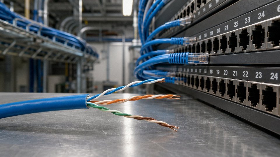
How TIA-568, ISO/IEC 11801, and UL 444 Define Cat 5 Electrical Limits
The 125 V AC ceiling on Cat 5 and Cat 5e cable isn’t an arbitrary marketing figure — it traces back to specific clauses in interlinked standards, and understanding where each number comes from changes how you specify, install, and troubleshoot.
TIA-568 and the 125 V Operating Ceiling
TIA-568-C.2, and its current successor TIA-568.2-D, define horizontal cabling component requirements including the maximum continuous operating voltage for balanced twisted-pair cable. The relevant clause sets 125 V AC as the upper limit for installed horizontal cabling — this covers the conductors, insulation, and connecting hardware taken together as a system. The successor revision didn’t raise that ceiling; it carried it forward while adding more explicit language around PoE application classes. ISO/IEC 11801 aligns closely, which matters if you’re specifying cable for a project that ships into Europe, Southeast Asia, or anywhere the IEC framework governs procurement and inspection.
One practical implication installers sometimes miss: the 125 V limit applies to the cabling system, not just the cable itself in isolation. That means your patch panels, keystone jacks, and field-terminated connectors all need to be rated to the same level. Swapping in cheaper unrated connectors on a PoE run because “it’s only 48 V anyway” is the kind of shortcut that fails a UL-listed building inspection — or worse, fails quietly in the ceiling.
UL 444 Dielectric Strength: What the Test Actually Does
UL 444 Section 6 requires completed Cat 5/5e cable to survive a dielectric strength test of 2,500 V AC conductor-to-conductor for one continuous minute. That’s applied to finished cable, not just raw insulation material — the geometry, the twist, the jacket compression all factor into whether it holds.
Failure mode is worth understanding because it’s not always obvious from the outside. When insulation punctures under high-potential testing, you typically see carbonization tracks along the polyethylene or FEP insulation — thin, dark lines where the dielectric broke down and current arced through. On XLPE-insulated cable the char is harder to spot without cutting the jacket. In a production or incoming-inspection context, a cable that fails the UL 444 hi-pot test but doesn’t visibly burn can still have compromised insulation resistance at normal operating voltages, which leads to intermittent noise and phantom PoE negotiation failures downstream.
UL 444 requires a 2,500 V AC dielectric strength test on completed Cat 5e cableTrue
UL 444 Section 6 specifies conductor-to-conductor dielectric strength testing at up to 2,500 V AC for one minute on finished cable, well above the 125 V AC operating ceiling defined by TIA-568.
IEC 61156-5 Insulation Resistance and the Humidity Problem
IEC 61156-5 sets a minimum insulation resistance of 500 MΩ·km at 20°C for Cat 5e cable. That figure sounds enormous — and at room temperature in a clean conduit run, it is. The problem is humid or wet environments, where polyethylene insulation that absorbed even small amounts of moisture over months of outdoor or plenum exposure can see insulation resistance drop by one to two orders of magnitude. At that point you’re still well above the threshold for signal integrity, but if you’re relying on the insulation to hold a continuous voltage near the 125 V limit, you’re operating with a reduced safety margin that the original test conditions didn’t model.
Runs longer than roughly 80–90 m in humid plant environments deserve a quick insulation resistance check before commissioning PoE equipment. Cheap IR meters in the 500 V range are sufficient; you don’t need a full hi-pot rig for field verification.
NEC Article 800 and the 150 V Ground Ceiling
NFPA 70 Article 800 classifies Cat 5 as Communications Wiring and legally restricts its use to circuits not exceeding 150 V to ground. This creates a small but real headroom between the 125 V TIA operating ceiling and the NEC legal ceiling — it does not mean you can legally run 149 V through Cat 5. The TIA limit is the governing design constraint; the NEC limit is a code compliance boundary that sits just above it. The gap exists partly to accommodate transient conditions without immediately putting an installation out of code, not to invite uprating.
Derating in Real Installations
Listed voltage and usable voltage in a conduit bundle are different numbers. TIA-568.2-D acknowledges that ambient temperature above 30°C or tightly bundled installations require derating. In practice, a 24-conductor bundle in a 45°C mechanical room — not unusual near HVAC equipment or in tropical climates — can push the practical operating ceiling down to somewhere in the 90–105 V AC range, depending on load and bundle geometry. Run your derating calculation before assuming the full 125 V is available.
The Regulatory Chain Down to the Installer
IEEE 802.3 annexes governing PoE explicitly reference TIA-568 cabling infrastructure requirements when defining compatible installations. This means the chain from standards body to your field tech is direct and traceable: IEEE 802.3bt defines the power levels, defers to TIA-568 for cabling limits, TIA-568 sets 125 V AC, UL 444 verifies the cable can physically withstand far more than that, and NEC Article 800 sets the legal usage boundary. Every link in that chain terminates at the installer pulling cable in the field. If the cable isn’t UL 444 listed to begin with, the entire compliance argument falls apart regardless of what the datasheet claims.
Power over Ethernet Voltage Realities: What Cat 5 and Cat 5e Actually Carry Today
In most working networks today, Cat 5e isn’t carrying anywhere near 125 V. It’s carrying PoE — and the real voltage on those conductors sits between 44 V and 57 V DC depending on which IEEE standard your switch is implementing. That gap between the rated ceiling and the actual operating point is comfortable on paper. Where things get complicated is current, resistance, and heat — none of which show up in a simple voltage rating.
IEEE 802.3af (PoE Type 1): The Easy Case
The original PoE standard, 802.3af, delivers 44–57 V DC at the PSE with a maximum of 15.4 W sourced and roughly 12.95 W available at the powered device after cable losses. Current is low — under 350 mA per pair — and Cat 5e handles this without complaint on runs up to 100 m. Thermal rise is negligible in lightly loaded bundles. For access points, VoIP phones, basic IP cameras: no concerns with properly terminated Cat 5e here.
IEEE 802.3at (PoE+ Type 2): Still Within Voltage Limits, But Watch the Resistance
PoE+ runs at 50–57 V DC with up to 30 W at the PSE. Voltage is still well inside the 125 V ceiling. The issue that starts to appear is conductor resistance. TIA-568 caps Cat 5e loop resistance at 25.0 Ω for a 100 m channel. At PoE+ current levels (up to about 600 mA), that 25 Ω loop can drop 15 V or so — which is why 802.3at requires a minimum PD input of 42.5 V and PSEs are spec’d to push the higher end of the voltage window to compensate. A borderline cable — slightly undersized conductors, a corroded connector, an informal splice someone did three years ago — starts to matter at this power level in a way it simply didn’t at 802.3af.
IEEE 802.3bt (PoE++ Type 3 and Type 4): Voltage Is Fine, Heat Is Not
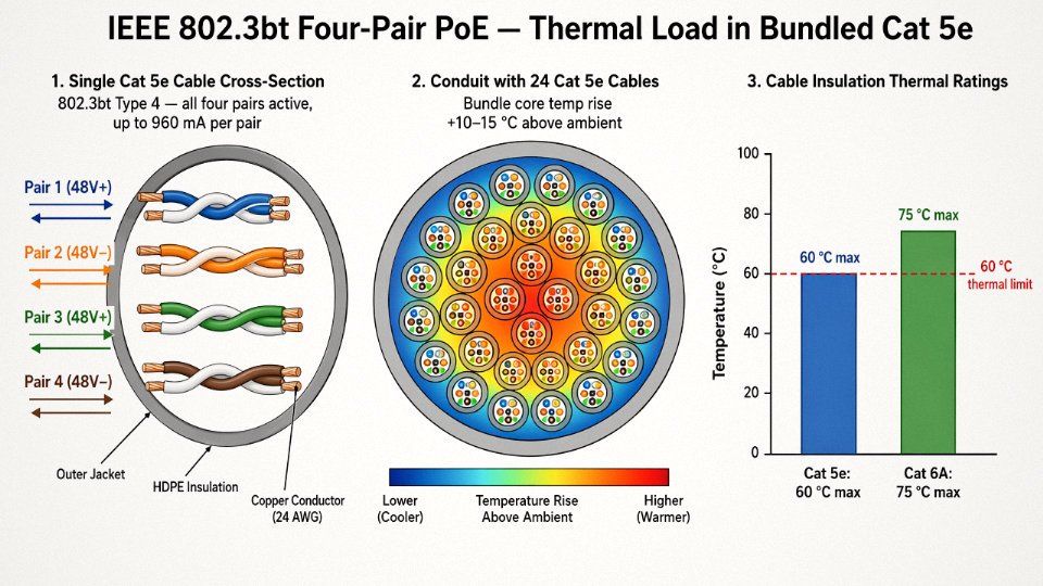
802.3bt is where the conversation shifts entirely. Type 3 sources up to 60 W; Type 4 goes to 90 W at the PSE, with up to 71.3 W reaching the device. Voltage stays at or below 57 V DC — technically compliant with Cat 5e’s rating — but all four pairs now carry current simultaneously, and I²R heating across a 24 AWG conductor becomes the dominant concern. At 90 W sourced over two pairs (Type 3 uses two pairs per polarity), you’re looking at roughly 960 mA per pair. The heat generated isn’t catastrophic in a single cable, but cables don’t live alone.
The ANSI/TIA-568.2-D annex on PoE is worth reading carefully if you’re running high-density PoE infrastructure. A bundle of 24 Cat 5e cables all carrying 802.3bt loads can see a temperature rise of 10–15°C above ambient — the actual number depends on bundle diameter, conduit fill, and ambient temperature in the tray. Cat 5e insulation is rated to 60°C. Cat 6A gets you to 75°C. That 15°C difference is your entire thermal margin in a warm ceiling plenum in summer. Cat 5 in a tightly packed conduit running 802.3bt to 24 PTZ cameras is not a comfortable situation.
Cat 5e is electrically safe for IEEE 802.3bt voltage levels up to 57 V DCTrue
The 57 V DC maximum under 802.3bt remains well below Cat 5e's 125 V AC operating ceiling defined by TIA-568. The real constraint at this power level is thermal, not voltage breakdown.
The Worked Example: A 90 m PoE+ Run to an IP Camera
Take a 90 m Cat 5e horizontal run — realistic in a warehouse or parking structure. TIA-568 specifies a maximum DC loop resistance of 9.38 Ω per 100 m for 24 AWG conductors (both conductors combined). Scale that to 90 m and you get roughly 8.44 Ω of loop resistance.
At 802.3at’s maximum current of approximately 600 mA:
Voltage drop = 0.600 A × 8.44 Ω ≈ 5.1 V
If the PSE outputs 52 V (a typical mid-range value, not the maximum), the PD sees about 46.9 V — comfortably above the 42.5 V minimum input. Fine. But run the same cable with a worn punch-down adding 2–3 Ω of contact resistance at each end, and that margin disappears fast. The voltage rating of Cat 5e was never the issue; it’s the accumulated resistance of a real installation that determines whether the camera boots reliably on a cold morning or sits in a reboot loop.
The practical takeaway: for 802.3af and 802.3at, Cat 5e is genuinely adequate on runs under 90 m in normal bundle densities. For 802.3bt Type 3 or Type 4 in high-density deployments, the voltage compliance is real but thermal de-rating and conductor resistance together argue strongly for Cat 6A — not because Cat 5e breaks down electrically, but because the margins get thin enough that the first bad connector or warm summer in a congested tray can cause intermittent faults that are miserable to diagnose.
Cat 5 in Building Automation, CCTV, and Low-Voltage Control Circuits: Voltage Boundaries in Practice
The 125 V AC rating sounds generous until you realize that half the problems with repurposed Cat 5 wiring have nothing to do with voltage at all. They stem from jacket listings, current limits, and frequency response — things the voltage spec says nothing about.
CCTV and IP Camera Power
Passive PoE injectors for analog cameras and budget IP cameras typically push 12–24 V DC down a Cat 5 pair. Electrically, that’s comfortably inside the cable’s voltage envelope. The problem shows up when you look at current. NEC Article 725 caps Class 2 circuits at 100 mA at 12 V (roughly 1.2 W at that voltage point). Cheap passive injectors — the kind that ship in bulk bags without UL listing — frequently exceed this threshold, which means the installation technically requires Class 2 listed cable, not just any Cat 5 UTP off a reel. The voltage is fine. The regulatory classification is not.
In practice, a lot of small commercial CCTV installs get away with this because nobody inspects the cable jacket listing. That changes the moment there’s a fire or an insurance claim.
Access Control and Intercom Wiring
RS-485 signal levels — 3.3 V or 5 V differential logic with a 12 V bias rail for line termination — are well within Cat 5’s voltage limits, and the cable’s 100 Ω characteristic impedance is a reasonable match for RS-485 bus requirements. At runs under roughly 250–300 m (the exact limit depends on baud rate and the number of nodes on the bus), Cat 5 performs acceptably. Beyond that, the impedance mismatch accumulates, reflections degrade signal integrity, and you start seeing intermittent reader faults that are misdiagnosed as hardware failures. Proper termination resistors at both ends of the bus matter here more than cable brand.
BMS and HVAC Sensor Wiring
Twenty-four volt AC thermostat and actuator circuits are textbook low-voltage work, and Cat 5 handles the voltage without complaint. The catch is NEC Article 725.179, which requires the cable jacket to carry a Class 2 or Class 3 listing for these circuits. A standard Cat 5 UTP jacket listing (typically CM or CMR) does not automatically satisfy this requirement, even though the electrical parameters overlap. Specifying cable that carries both a Cat 5e performance rating and a CL2 or CL3 jacket listing isn’t difficult — several manufacturers offer it — but it has to be called out explicitly on the drawing. Assuming a CMR-rated Cat 5e reel from the warehouse covers a 24 V AC actuator circuit is the kind of shortcut that fails inspection.
Alarm and Fire Notification Ancillary Circuits
Supervised 24 V DC loop wiring for alarm panels sits well inside Cat 5’s voltage rating. NFPA 72 doesn’t care. What it does care about is pathway classification: in plenum spaces or vertical runs through floor-to-floor penetrations, NFPA 72 requires FPLR or FPLP rated cable. Cat 5 — even CMR or CMP rated — is not a listed substitute for FPL-series cable in fire notification circuits. Voltage compliance is irrelevant here. Cable listing is the controlling factor.
70 V Audio Distribution
A 70.7 V RMS constant-voltage audio line falls below the 125 V ceiling, so the voltage argument for using Cat 5 holds up on paper. What doesn’t hold up is audio quality above roughly 8–12 kHz. Cat 5’s distributed capacitance runs somewhere in the 50–100 pF/m range depending on construction, and at 50 m or more that capacitance forms a low-pass filter with the source impedance. Treble rolloff becomes audible in speech-intelligibility systems. Background music in a retail space might tolerate it; a paging system in a noisy warehouse probably will not.
Cat 5's 125 V rating makes it code-compliant for any low-voltage building circuit below that thresholdFalse
Voltage rating is only one criterion. NEC Article 725 current limits, jacket listing requirements (CL2/CL3 vs. CM/CMR), NFPA 72 FPL-series mandates for fire notification pathways, and application-specific frequency response constraints can each independently disqualify Cat 5 for a given circuit regardless of voltage compliance.
Voltage rating is a gate, not a green light. Every non-data application requires a separate check against the governing code article, the required jacket listing, the operating current, and — for audio — the frequency range of the signal. A cable that passes the voltage test can still fail all four of the others.
Insulation, Jacket, and Conductor Materials That Determine Cat 5 Voltage Withstand
The 125 V AC operating ceiling isn’t an arbitrary number someone picked at a committee meeting. It falls directly out of the physical materials used to construct the cable — conductor gauge, insulation wall thickness, dielectric properties, and jacket compound — and understanding that chain of reasoning is what separates a procurement engineer who can evaluate a cable datasheet critically from one who just checks a spec box.
Conductor: 24 AWG Solid Annealed Copper
Standard Cat 5 and Cat 5e use 24 AWG solid annealed copper, nominally 0.511 mm diameter. The skin effect question comes up occasionally — at 100 MHz, current does concentrate toward the surface — but skin effect is completely irrelevant to voltage withstand or DC resistive heating. What matters for PoE is straightforward Ohm’s law: the conductor’s DC resistance, typically 9.38 Ω/100 m or less per TIA-568, determines how much heat is generated under sustained current load. IEEE 802.3bt (PoE++) pushes up to roughly 600–960 mA per conductor pair depending on topology, and at that current level over a 100 m run, resistive losses translate to real temperature rise in the insulation. The conductor itself doesn’t fail. The insulation around it does, if thermal limits are exceeded — which is why the plenum vs. riser distinction matters more than most installers realize.
Primary Insulation: HDPE and the Dielectric Strength Math
The primary insulation extruded directly over the conductor is typically high-density polyethylene (HDPE) or foam-skin PE, with a wall thickness in the range of 0.20–0.25 mm on finished Cat 5/5e. HDPE has a dielectric strength of approximately 18–20 MV/m under standard test conditions. Run the arithmetic: a 0.20 mm wall at 18 MV/m gives a theoretical breakdown voltage around 3,600 V, and at 20 MV/m it’s closer to 4,000 V. That’s why the UL 444 requirement to withstand 1,000–2,500 V AC for one minute passes with considerable margin. The operating ceiling of 125 V represents less than 4% of the insulation’s actual breakdown capacity under ideal conditions.
The operative phrase is “ideal conditions.” Thin spots in the insulation wall — caused by poor concentricity during extrusion — are where cables actually fail dielectric tests. A nominal 0.22 mm wall with a ±10% concentricity tolerance could have local minimums of 0.20 mm or less; at ±5% it holds tighter. Jinda’s extrusion lines control insulation wall concentricity to ±5% tolerance, which means dielectric performance is governed by design rather than being limited by whatever the worst thin spot happens to be on a given meter of cable. Over a 1,000-reel procurement, that consistency matters.
Outer Jacket: PVC, CMR, CMP, and Thermal Headroom
The outer jacket on standard riser-rated (CMR) Cat 5e is PVC, typically 0.5–0.7 mm wall thickness depending on finished OD, which usually runs 5.0–6.0 mm. PVC dielectric strength is in the 15–20 MV/m range, adding another layer of voltage isolation on top of the primary insulation — though in normal operation the jacket’s role is more mechanical and environmental than electrical.
Plenum-rated (CMP) cable substitutes FEP or LSZH compounds for the jacket and sometimes the primary insulation as well. FEP carries a 90°C continuous temperature rating versus roughly 60°C for standard PVC. In a dense PoE++ installation — say, a ceiling plenum serving 40+ 802.3bt-powered access points — ambient temperatures in the plenum space can climb 10–20°C above room temperature, especially in summer. FEP’s additional thermal headroom isn’t theoretical padding; it’s what keeps insulation from softening and losing dielectric integrity over a 15-year cable lifetime under that kind of sustained thermal load.
Shielded Cat 5e: The Grounding Problem Most Installers Underestimate
Shielded variants — F/UTP (foil shield over all pairs) or S/STP (individual pair shields plus overall braid) — introduce a conductor that is geometrically close to all four pairs simultaneously. If that shield is properly terminated and grounded at one end (standard practice to avoid ground loops), it sits at a defined potential. If it’s left floating — which happens more often than it should, usually because the installer used an unshielded patch panel and didn’t notice the shield tail — it can capacitively couple to whichever pair is carrying the highest voltage at any moment. In a mixed PoE and data environment, that can mean a floating metallic layer sitting somewhere between 0 V and 48–57 V DC with no defined path to ground.
A floating shield in a Cat 5e F/UTP cable can develop an unintended voltage potential in PoE-powered installations if not properly terminated.True
An ungrounded foil shield acts as a floating conductor and will capacitively couple to adjacent pairs carrying PoE voltage, potentially creating an undefined potential difference that poses both a signal integrity and a low-level electrical hazard.
It won’t electrocute anyone. But it will cause EMC problems, and in sensitive control environments it occasionally causes enough noise to trip diagnostic alarms. The fix is simple — terminate the drain wire properly — but the problem is subtle enough that it gets missed on first commissioning and diagnosed weeks later.
Cat 5 vs. Cat 5e vs. Cat 6 vs. Cat 6A: Voltage Ratings, PoE Capacity, and When to Upgrade
One of the most persistent misconceptions in structured cabling procurement is that higher-category cables carry a higher voltage rating. They don’t. Cat 5, Cat 5e, Cat 6, and Cat 6A all share the same 125 V AC operating ceiling under TIA-568. If you’re specifying Cat 6A because you believe it tolerates more voltage, that’s not the right reason — though it may still be the right choice.
Cat 6 and Cat 6A have a higher voltage rating than Cat 5e under TIA-568False
All four UTP categories — Cat 5, Cat 5e, Cat 6, and Cat 6A — share the same 125 V AC operating ceiling defined by TIA-568. The category upgrade path improves transmission performance, thermal handling, and PoE power delivery efficiency, not the voltage ceiling itself.
Where the Categories Actually Diverge: Conductor Gauge and Resistance
The real story is conductor gauge. Cat 5e typically uses 24 AWG conductors (roughly 0.511 mm diameter), while Cat 6 and Cat 6A step up to 23 AWG (about 0.574 mm). That difference sounds trivial on paper. In practice, it cuts DC loop resistance from around 9.4 Ω/100 m down to roughly 7.5 Ω/100 m — a reduction somewhere in the 18–22% range depending on conductor purity and stranding, and that matters enormously the moment you start pushing power through the cable alongside data.
Lower resistance means two things: better voltage delivery at the far end of a long run, and less I²R heat generated in the cable bundle. Both matter for PoE, and the second one matters more than most people realize when cables are bundled in conduit or cable trays at 50 or 100 pulls deep.
PoE Wattage and the Thermal Case for Cat 6A
IEEE 802.3bt Type 4 (PoE++) delivers up to 90 W at the switch port and up to 71.3 W at the powered device, operating at up to 57 V DC. TIA-568.2-D and IEEE 802.3bt both explicitly recommend Cat 6A for these deployments. The reason isn’t voltage headroom — it’s the combination of lower resistance, the Cat 6A temperature rating of 75°C versus 60°C for Cat 5e, and a meaningfully lower bundled-cable derating penalty.
When you run 24 AWG Cat 5e in a tray bundle of 48 or more cables all carrying PoE simultaneously, the cumulative heat can push conductor temperatures toward the jacket’s rated limit. At that point, TIA-568.2-D requires derating the allowable current, which reduces effective PoE wattage delivery — sometimes enough to drop Type 3 or Type 4 devices off the network intermittently. Cat 6A’s 23 AWG conductors generate less heat per cable and tolerate more of it before derating kicks in.
Decision Matrix: Application vs. Recommended Cable Category
| Application | Recommended Minimum | Max Voltage (Operating) | Max PoE Wattage (PD) | Max Distance | Notes |
|---|---|---|---|---|---|
| Standard Ethernet data only | Cat 5e | 125 V AC | N/A | 100 m | Entirely adequate; no power concern |
| PoE Type 1 (802.3af, 15.4 W PSE) | Cat 5e | 125 V AC | ~12.95 W at PD | 100 m | Cat 5e handles this with margin |
| PoE Type 2 (802.3at, 30 W PSE) | Cat 5e | 125 V AC | ~25.5 W at PD | 100 m | Verify bundle size; derate if >24 cables |
| PoE Type 3 (802.3bt, 60 W PSE) | Cat 6 preferred | 125 V AC | ~51 W at PD | 100 m | Cat 5e marginal in dense bundles |
| PoE Type 4 / PoE++ (90 W PSE) | Cat 6A recommended | 125 V AC | ~71.3 W at PD | 100 m | Cat 5e not recommended; thermal risk |
| Building automation / BAS (24 V DC signals) | Cat 5e | 125 V AC ceiling | Low-power signal only | Varies by protocol | Confirm shield requirement per system |
| Analog CCTV / low-voltage control | Cat 5e | 125 V AC ceiling | N/A | Application-dependent | Verify NEC/local code for mixed-use |
Cost-Benefit: The 1,000-Port Deployment Reality
Cat 6A bulk cable typically costs 30–60% more per meter than Cat 5e, depending on jacket type, country of purchase, and order volume. On a 1,000-port enterprise deployment averaging roughly 60–70 m per run, that premium adds up to a real number — somewhere in the range of $15,000 to $40,000 extra in raw cable cost, depending heavily on regional pricing and specification tier. That sounds like a reason to stick with Cat 5e.
It often isn’t. Labor is typically 3–5× the material cost in a finished installation. If Cat 5e is under-specified for a PoE++ rollout and thermal degradation causes intermittent failures within five years — which I’ve seen happen in dense access-switch closets with no active cooling — the cost of recabling even a partial floor while the building is occupied dwarfs that upfront delta. Tenants don’t vacate conveniently, and cut-in cable trays never look the same twice.
Auditing Existing Cat 5e for PoE++ Suitability
Millions of meters of Cat 5e are already in place in commercial buildings installed between the late 1990s and mid-2010s. Before writing it off or blindly running PoE++ through it, audit it properly. Time Domain Reflectometry (TDR) will reveal any impedance anomalies, damaged pairs, or connector problems that increase effective resistance. DC loop resistance measurement on each pair should come in under 17.6 Ω for a 100 m run (the TIA limit for 24 AWG); anything significantly higher suggests a bad termination, a damaged conductor, or a substandard cable run worth investigating before applying full PoE++ load. If the existing plant passes both tests and bundles are modest — say, under 24 cables running PoE simultaneously — Cat 5e may serve Type 3 loads acceptably. For Type 4, the recommendation is to replace it, not to test your luck with 71 watts and inadequate derating margin.
Field Testing and Certification: Verifying Cat 5 Voltage and Electrical Performance After Installation
The TIA-568 field test suite is thorough, but it does not directly prove voltage withstand. Wiremap, length, insertion loss, NEXT, PS-NEXT, ELFEXT, PS-ELFEXT, return loss, and propagation delay — all of these confirm signal integrity and pair geometry. None of them tell you whether the insulation will hold at 125 V AC, or even at the 48–57 V DC a PoE++ switch is pushing down that cable right now. For voltage assurance, you need two additional tests that most installers skip: DC resistance balance and insulation resistance. On PoE-heavy deployments or any installation where Cat 5e is being used in a building automation or low-voltage control role, skipping these is a real risk, not a theoretical one.
DC Loop Resistance: The First Voltage-Related Check
TIA-568 and IEC 61935-1 both specify a maximum loop resistance for Cat 5e: 25 Ω per pair at 100 m, at 20 °C. That figure accounts for normal 24 AWG solid copper conductors and standard splice losses. When you measure 28 or 32 Ω on a pair, the cable has a problem — a poor crimp at one end, a nick in the conductor from a staple gun or cable tie overtightened during the pull, or conductors that were stretched under excessive tension. The resistance elevation itself causes voltage drop that can push a marginal PoE PD below its operating threshold. Less obviously, the same mechanical damage that raises resistance also thins or stress-cracks the insulation, directly eating into the voltage withstand margin. A pair reading 32 Ω on a 100 m run is a cable you should not trust to hold 125 V reliably. Remediation usually means re-terminating both ends first; if that doesn’t fix it, the run has physical damage and needs replacement.
Insulation Resistance Testing
IR testing applies 500 V DC between conductors — or between a conductor and the shield on screened cable — and measures the leakage resistance in megaohms. IEC 61156 requires ≥ 500 MΩ·km normalized; for a single 100 m run that translates to ≥ 5,000 MΩ. Readings below that threshold are a flag for moisture ingress, a jacket breach, or a manufacturing defect in the insulation wall. In practice, a reading around 1,000–2,000 MΩ on a run that was fine at commissioning and then got wet during a roof repair is almost always moisture, and it usually recovers after the cable dries — but “usually” is not good enough in a PoE circuit running a fire panel controller or a surveillance camera on a remote pole. Use a Megger MIT430 or similar instrument rated for this voltage range. Do not use a standard multimeter; its test voltage is far too low to stress-test insulation meaningfully.
Hi-Pot Testing: Factory vs. Field
UL 444 factory QC applies 1,000–2,500 V AC for 60 seconds to verify dielectric integrity. In the field you cannot do that safely with connected equipment; even a 1,000 V AC test can damage switch ports or IP cameras left plugged in. The practical field approach is a 500–1,000 V DC hi-pot test with all network equipment disconnected. A pass means no breakdown or sudden current spike during the 60-second dwell. Any current surge or insulation collapse at these voltages on cable that is only rated for 125 V AC operating service is a serious finding.
A Cat 5e cable that passes the full TIA-568 signal performance suite is automatically confirmed safe for its rated voltage.False
TIA-568 field tests verify signal and transmission parameters only. Voltage withstand is confirmed separately through insulation resistance testing and hi-pot procedures, which are not part of the standard field certification suite.
Instruments and Interpretation
The Fluke DSX-8000 CableAnalyzer is the workhorse for TIA-568 electrical certification — it will catch wiremap faults, insertion loss failures, and NEXT margin issues that indicate pair damage. It will not tell you anything about insulation resistance. For IR work, the Megger MIT430 (or equivalent instruments from Hioki or Kyoritsu) is appropriate; set the test voltage at 500 V DC for standard Cat 5e, read after a stable 60-second dwell, and note the polarization index trend if readings are borderline. A result that starts at 8,000 MΩ and climbs to 15,000 MΩ during the dwell is healthy. One that starts at 4,000 MΩ and drifts downward is telling you moisture or contamination is present.
Marginal IR results — say, 3,000–4,500 MΩ on a 100 m run — are genuinely ambiguous. Temperature affects insulation resistance significantly; a cold warehouse in January can read 40–50 % higher than the same cable in a humid equipment room in August. If you’re borderline, re-test at a consistent temperature, check the cable routing for water exposure points, and document the conditions.
Documentation and Traceability
Every test result should be archived with the cable reel lot number, installation date, ambient temperature at time of test, and technician ID. This is not bureaucratic overhead. When a PoE injector trips its overcurrent protection on port 14 six months after commissioning, the first question from any competent support team is whether that run was tested and what the IR reading was at handover. Jinda’s technical support team requires this documentation from project partners before opening a warranty investigation on voltage-related field failures — not because it’s policy for its own sake, but because a 32 Ω loop resistance or a 1,200 MΩ IR reading at commissioning changes the entire diagnosis. Without the baseline, you’re guessing. With it, you can usually trace the fault to installation damage, a specific reel, or a termination practice within a single site visit.
Common Wiring Mistakes That Push Cat 5 Beyond Its Voltage and Current Limits
Most voltage-related failures in Cat 5/5e installations don’t come from a single dramatic error. They accumulate — a shortcut here, an assumption there — until something overheats, a PoE device refuses to negotiate, or worse, insulation breaks down quietly over months before anyone notices.
Paralleling Pairs to Boost Current Capacity
This one shows up more often than it should, usually on retrofit jobs where someone needs to squeeze PoE++ out of an existing run that’s marginal on resistance. The logic seems sound: bond pairs 1&2 with 3&6, double the conductors, halve the resistance. In practice it violates TIA-568 outright, and the physics punishes you fast.
Contact resistance between paralleled conductors is never equal. Even a 20–50 mΩ difference between two crimped connections causes one pair to carry disproportionately more current. That pair heats up, its resistance rises further, and the imbalance compounds. The PoE detection and classification handshake — which relies on precise impedance signatures seen by the power sourcing equipment — reads garbage and either refuses to power the device or locks into a lower power class. You’ve gained nothing and created a localized hot spot that standard thermal inspection won’t catch because it’s buried inside a bundle.
Running Cat 5 in the Same Conduit as 120/240 V AC
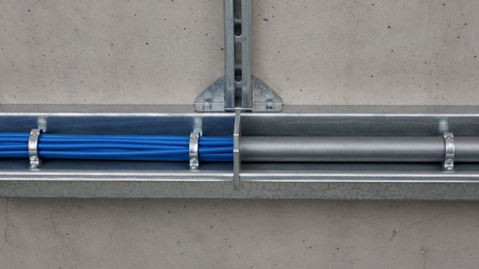
NEC Article 800.133 is clear: communications cables cannot share a conduit with power conductors. The prohibition applies even though Cat 5’s operating ceiling sits at 125 V AC, well below typical 240 V building circuits. The hazard isn’t direct conduction — it’s inductive and capacitive coupling. A 240 V AC line running parallel to a Cat 5e run for 15–20 meters can induce transients of 50–150 V onto the data pairs depending on cable spacing and frequency harmonics from variable-speed drives or fluorescent ballasts nearby. Those transients ride on top of whatever PoE voltage is already present on the pairs, pushing instantaneous combined voltage toward or past the 125 V ceiling in unpredictable bursts.
NEC Article 800.133 prohibits communications cables from sharing conduit with power conductors, regardless of the communications cable's own voltage rating.True
NEC Article 800.133 establishes separation requirements for communications cables and power conductors. This applies based on the power conductor voltage classification, not the communications cable rating.
Excessive Bundle Density Without Thermal Derating
A bundle of 50 Cat 5e cables all carrying Type 3 or Type 4 PoE behaves like a poorly designed resistive heater. Mutual heating across a dense bundle raises jacket surface temperature by roughly 20–25°C above ambient, depending on bundle diameter, airflow, and installation method. Standard PVC jackets are rated to 60°C. Install that bundle in a ceiling plenum already sitting at 35°C ambient on a hot summer day, add 20–25°C of self-heating, and your thermal margin is effectively zero. Insulation degradation at that point isn’t a possibility — it’s a timeline.
LSZH or plenum-rated (CMP) cables handle this better, but they don’t eliminate the problem. The real fix is derating: reduce the number of PoE-active cables per bundle, use cable trays with spacing rather than tight conduit fill, and treat high-density PoE zones as a thermal engineering problem, not just a patching exercise.
Deploying Original Cat 5 (Pre-2001) for Any PoE Application
Legacy Cat 5 — manufactured before TIA-568-C.2 consolidated PoE guidance — was built to different dimensional tolerances. Insulation walls on some older constructions run thinner, and DC loop resistance on 24 AWG runs can exceed the 25 Ω per 100 m limit that IEEE 802.3 PoE standards assume. TIA-568-C.2 simply does not extend PoE support to original Cat 5; the standard explicitly covers Cat 5e and above.
In practice, you often can’t visually distinguish a 1998-vintage Cat 5 pull from a Cat 5e run without checking the jacket print date and measuring resistance. If the print year is missing or the DC resistance tests high, pull it and replace it before deploying PoE. The cost of a re-pull is a fraction of the cost of diagnosing intermittent powered device failures across a 200-port deployment.
Improper Termination Creating Voltage Drop Under Load
A 110-block termination that’s half-punched, or an RJ-45 plug with more than 13 mm of untwisted pair (TIA-568’s stated limit), introduces higher local resistance and elevated capacitance at that point. Under PoE load, this creates a localized voltage divider. The PSE may be sending 52 V; the PD sees 47 V and sits just at the edge of its minimum operating threshold. The device runs, but unreliably — periodic resets, failed class negotiation, or thermal stress inside the PD’s input stage. Technicians chase the symptom at the device and miss the termination entirely.
The fix takes two minutes with a proper punch-down tool and a calibrated crimp. The diagnostic process, if you’re chasing it blind across a ceiling grid, can take days.
Ground Loops in Shielded Cat 5e Installations
F/UTP Cat 5e grounded at both ends in an industrial plant with multiple ground potential points will carry circulating current on the shield. That’s expected and usually tolerable for signal integrity. The problem surfaces when ground potential differences run 10–30 V between a control room and a remote panel — not unusual in older plants with poor bonding practice. That circulating current induces a voltage offset onto the conductors relative to local ground. Add it to the 48–57 V DC already present on the pairs from PoE, and you’re working with a combined effective voltage that may approach 80–100 V on a system nominally rated for 125 V. The margin shrinks fast, and if a transient spike arrives from a relay switching nearby, you’re over the ceiling.
Single-point grounding of the shield, or using a ground isolation module at one end, eliminates the loop. It’s a standard practice in industrial Ethernet; it just gets skipped when IT-trained installers handle the cabling without plant-floor context.
Frequently Asked Questions About Cat 5 Voltage Rating
Can Cat 5 cable carry 120 V AC for lighting or outlet circuits?
No — and this comes up more often than it should, usually when someone notices that 120 V sits just below the cable’s 125 V rated ceiling and figures it must be fine.
It isn’t. NEC Article 800 classifies Cat 5 as communications cable, not branch-circuit wiring. The conductors are typically 24 AWG solid copper, which carries nowhere near the cross-section required for a 15 A or 20 A branch circuit. More critically, Cat 5 insulation carries no listing for sustained power-frequency voltage, no short-circuit protection rating, and no compliance with NEC Article 310 conductor requirements. Running 120 V AC through a Cat 5 cable to feed an outlet or light fixture is a code violation in any jurisdiction that follows the NEC or equivalent building codes — and a genuine fire hazard. The jacket will overheat, the insulation can char, and standard Cat 5 insulation has no self-extinguishing rating adequate for branch-circuit fault conditions. Don’t do it.
Is Cat 5e safe for all four types of PoE — Type 1 through Type 4?
From a pure voltage standpoint, yes. All IEEE 802.3 PoE variants operate between roughly 44 V and 57 V DC, comfortably inside the 125 V AC ceiling. The real concern with Cat 5e and high-wattage PoE is thermal, not dielectric.
PoE++ Type 4 (IEEE 802.3bt) delivers up to 90 W at the PSE, which means meaningful current on all four pairs. In a tightly bundled conduit run — say, 24 cables or more — the heat generated by resistive losses in 24 AWG conductors accumulates across the bundle. TIA-568.2-D is explicit: Cat 6A is the recommended minimum for Type 3 and Type 4 deployments, partly because of its lower DC resistance and partly because Cat 6A jacket compounds typically carry higher continuous-temperature ratings than legacy Cat 5e. In practice, a short Cat 5e homerun to a single IP camera on PoE+ will be fine. A dense bundle of 48-port PoE++ switches fed over 80 m Cat 5e runs is where you start seeing thermal derating problems and intermittent link drops.
What is the voltage rating of Cat 5 vs. Cat 6 vs. Cat 6A?
All three share the same 125 V AC operating ceiling under TIA-568. Upgrading from Cat 5e to Cat 6 or Cat 6A buys you lower DC resistance, higher bandwidth headroom, and better thermal performance under PoE load — not a higher voltage rating.
Cat 6A has a higher voltage rating than Cat 5eFalse
TIA-568 specifies the same 125 V AC operating voltage ceiling for Cat 5, Cat 5e, Cat 6, and Cat 6A. The difference between categories relates to bandwidth, attenuation, crosstalk performance, and thermal characteristics under PoE load — not voltage tolerance.
Why does my PoE device keep dropping out at the end of a 90 m Cat 5e run?
Almost certainly a voltage drop problem, not a voltage rating problem — people confuse the two. At 90 m, Cat 5e loop resistance per pair typically runs somewhere in the range of 16–18 Ω depending on conductor quality and ambient temperature. Under PoE+ load (up to roughly 600 mA), that resistance drops around 9–11 V across the run. If your PSE is sourcing at 50 V, the powered device may be seeing 39–41 V — below IEEE 802.3at’s minimum 42 V operating threshold at the PD.
Options: shorten the run, pull Cat 6 cable with lower resistance conductors, or install a mid-span injector closer to the device. Replacing the switch port doesn’t help if the cable is the constraint.
Can I use outdoor-rated Cat 5e for direct-burial runs carrying PoE voltage?
Yes, provided the cable actually carries a proper direct-burial or outdoor listing — look for CMX rating or a PE-jacketed gel-filled construction, not just a cable marketed as “outdoor” without a UL or equivalent listing. The voltage rating stays at 125 V AC regardless of jacket type.
One thing installers routinely miss: any shielded outdoor Cat 5e (F/UTP or S/FTP) needs the shield and drain wire properly bonded to ground at the building entry point. A nearby lightning strike induces surge voltages that can easily exceed the cable’s 2,500 V dielectric withstand limit if the shield is left floating. In dry climates this gets skipped constantly. It causes expensive damage when a storm rolls through.
How does Jinda test Cat 5e cables for voltage compliance before shipment?
Every production reel goes through 100% conductor continuity testing, DC resistance measurement per pair, and insulation resistance testing at 500 V DC. During the extrusion process itself, spark testing is performed continuously along the full cable length at 6 kV DC — this catches pinholes and thin spots in the insulation before the reel is even finished. Finished cable samples from each production batch are submitted for UL 444 and IEC 61156 type testing, which includes the 2,500 V AC dielectric withstand test held for one minute without breakdown. Certificates of conformance are available for all export shipments, and Jinda’s quality records include traceability back to the specific production batch — useful for procurement managers who need documentation for customs, project specifications, or audit purposes.
Specifying and Sourcing Cat 5e Cable for Voltage-Sensitive Projects: A Procurement Checklist
By the time you reach the procurement stage, you’ve already done the engineering work — you know the voltage limits, you’ve assessed the PoE tier, you understand what the standards require. The problem is that none of that knowledge protects you if the cable you receive on-site doesn’t actually meet the spec on paper. Sourcing Cat 5e for any voltage-carrying application, whether PoE lighting control, IP cameras, or access control, requires a more disciplined checklist than most purchasing teams apply.
Minimum Specification Requirements
Start with what must appear on the cable jacket print itself. The voltage rating — 125 V AC — should be explicitly printed on the jacket alongside the UL 444 or IEC 61156-5 listing mark. If the jacket print only states “Cat 5e” with a speed rating and nothing else, that’s a flag worth investigating before accepting the reel.
Conductor gauge matters more than people think. For horizontal runs (wall-to-wall infrastructure cable), specify 24 AWG solid copper. For patch cords and equipment connections, 24–26 AWG stranded is appropriate, but confirm the stranding is consistent — irregular stranding affects contact resistance at the jack termination, which compounds voltage drop in PoE circuits. For the insulation material: PE (polyethylene) or FEP for plenum-rated cable, PVC for riser and general-purpose use. Don’t accept “thermoplastic insulation” as an answer — ask for the specific polymer.
Certificates and Test Records
Request the UL Yellow Card number or the IEC CB Scheme certificate number before you issue a purchase order, not after. Then verify it. Go to UL’s Product iQ database and confirm that the listed voltage rating on the certificate matches your application. Suppliers occasionally list a cable family under a certificate that technically covers only some variants within that family.
Beyond the certificate, ask for factory spark test records and insulation resistance test records for the specific production lot you’re receiving. Spark testing (typically 2,000–2,500 V AC applied along the length of each conductor) is a per-unit production test, not a type-approval test. Lot-specific records tell you whether that batch of cable was actually tested, not just whether the cable design passed a qualification test six years ago.
Jacket Temperature Rating and PoE Compatibility
For any installation running IEEE 802.3bt Type 3 or Type 4 (PoE++ at up to 57 V DC and 71.3 W at the PD), the jacket temperature rating deserves explicit attention. Standard PVC jackets are typically rated to 60°C, which is marginal when you bundle PoE cables tightly in conduit — bundle heating can push conductor temperature 10–20°C above ambient depending on fill ratio and airflow. Specify a 75°C-rated jacket as a minimum for bundled PoE runs. If the project involves high-density PoE deployment, consider whether Cat 6A is the more defensible long-term choice given its better thermal headroom and lower DC resistance.
The cable datasheet should state the thermal rating explicitly. “Category 5e” alone tells you nothing about temperature performance.
Conductor Purity: OFC vs. CCA
This one comes up constantly in competitive bids and it’s worth being blunt about. Specify oxygen-free copper (OFC) or bare copper (BC) conductor. Copper-clad aluminum conductors carry roughly 40% higher resistance than solid copper — that’s not a marginal difference. On a 90-meter horizontal run under a PoE load, CCA can push you past TIA-568’s DC loop resistance limit of 40 Ω, which means voltage drop at the powered device exceeds what the PSE can compensate for. You’ll see intermittent device resets or outright failure to power up, and it’s genuinely difficult to diagnose in the field without a proper DC resistance test.
CCA (copper-clad aluminum) Cat 5e cable fails TIA-568 DC resistance specifications on runs beyond approximately 60–70 meters under full PoE loadTrue
TIA-568 limits DC loop resistance to 40 Ω for a 100-meter channel. CCA conductors have approximately 40% higher resistivity than solid copper, which moves the failure threshold to roughly 60–70 meters depending on conductor gauge and contact resistance at terminations.
Long-Term Supply Considerations
For projects above 100,000 meters, batch-to-batch consistency becomes a real operational issue — not a theoretical one. Cable electrical characteristics, particularly capacitance unbalance and DC resistance, can drift enough between production runs to affect PoE performance in marginal installations. Request batch-to-batch consistency certificates and, for critical infrastructure projects, ask whether factory audit access is available. Shandong Jinda’s five production bases across China, covering 470,000 m² of manufacturing space with dedicated export logistics, provide the production scheduling transparency and volume capacity that large international deployments genuinely require across more than 50 countries.
Total Cost of Ownership
A cable unit price comparison that ignores installation labor, field certification cost, and remediation risk is not a cost analysis — it’s a guess. Properly specified Cat 5e or Cat 6A typically carries a 10–15% unit price premium over bottom-tier product, but a failed cable run in a commissioned building costs labor at full field rates plus disruption to other trades. Over a 10-year building lifecycle, that 10–15% premium routinely saves 3–5× in remediation. The math isn’t close.