Specifying the wrong power cable is one of those mistakes that rarely shows up immediately. You pull it through conduit, terminate it, energize the panel — and everything looks fine for six months. Then an undersized conductor running at sustained load heats past its rated temperature, insulation degrades quietly, and one morning you’re looking at an unplanned shutdown, a scorched junction box, and a rewiring job that costs three to five times what the correct cable would have cost upfront. Procurement managers feel this differently than maintenance engineers do, but the root cause is usually the same: the selection was made on price per meter without working through the actual application requirements first.
To choose the right power cable, you need to match four variables to your installation: the rated voltage of the circuit, the continuous current load (with derating for installation method and ambient temperature), the mechanical environment the cable will face, and the regulatory standard that governs your end market. Get all four right and the cable will outlast the equipment it feeds. Miss one and you’re either over-spending on unnecessary rating or, worse, running a latent fire and failure risk.
What makes this genuinely complicated is that each of those four variables interacts with the others in ways the datasheet doesn’t always make obvious — and the options multiply fast once you start factoring in conductor material, insulation type, armoring, and certification requirements. The rest of this guide works through each decision point the way you’d actually encounter it on a real project.
Decoding Voltage Ratings: Matching Cable Class to Your System’s Operating Voltage
Voltage rating is probably the single most misread piece of information on a cable datasheet. Buyers see “1 kV cable” and assume that covers any system running below 1,000 V. It’s close to right, but not exactly right — and the gap between “close” and “correct” is where failures happen.
The Three Voltage Bands and What They Actually Mean for Insulation
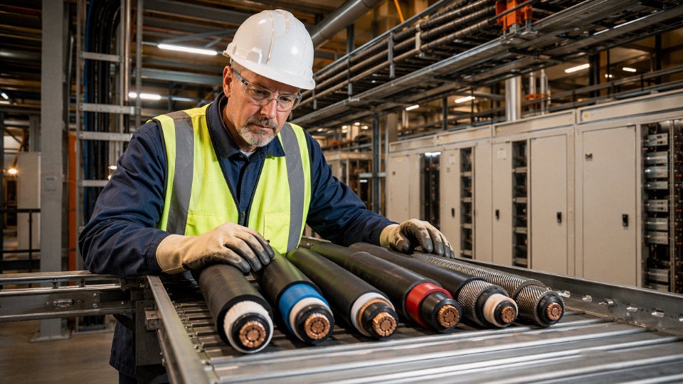
Low voltage covers systems up to 1 kV. This band handles the vast majority of building wiring, motor circuits, panel feeds, and light industrial distribution — roughly 60–70% of all installed cable globally falls here. The insulation wall on a typical LV cable is relatively thin, usually 0.7–1.0 mm on smaller conductors, because the dielectric stress is manageable.
Medium voltage runs from 1 kV up to 35 kV. This is substation feeders, primary distribution loops, wind farm collection circuits, large industrial plant main incomer cables. Insulation walls get substantially thicker — 3.4 mm to 8 mm or more depending on rated voltage — because you’re now dealing with dielectric stress that will erode inadequate insulation over months rather than cause an immediate flashover. Screening layers, bedding, and careful concentric conductor geometry matter here in ways they simply don’t at LV.
High voltage starts above 35 kV. Transmission-class cable. Completely different procurement and installation world — factory-jointed drum lengths, specialized installation crews, factory acceptance testing at customer request. If your project is HV, you already know it; this article is focused on the LV and MV range where most procurement mistakes occur.
Reading the U₀/U Notation Correctly
Every cable datasheet carries a voltage designation written as U₀/U, sometimes with a third figure Um for the maximum system voltage. U₀ is the rated voltage between any conductor and earth (or the metallic screen). U is the rated voltage between any two phase conductors. So a cable marked 0.6/1 kV is designed for phase-to-earth stress of 0.6 kV and phase-to-phase stress of 1 kV.
Match this against your system, not the other way around. A standard European 400 V three-phase system has a phase-to-earth voltage of 230 V and phase-to-phase of 400 V. The 0.6/1 kV cable comfortably covers both figures with margin to spare. A 6.6 kV distribution system — common in heavy industry and mining — runs 3.81 kV phase-to-earth, so the correct cable is 3.6/6 kV, governed by IEC 60502-2.
The Transient Overvoltage Problem Most Buyers Overlook
A system that nominally operates at 400 V does not stay at 400 V during every switching event. Capacitor bank switching, transformer energization, and nearby lightning strikes drive transient overvoltages that can reach 2–4× the nominal level for microseconds. IEC 60502-1 cables rated 0.6/1 kV are tested to withstand lightning impulse levels of 8 kV — that headroom is the real reason you don’t use a 450/750 V flexible cord on a fixed industrial installation even if the steady-state voltage is identical. Spec the cable to the standard, not just the nameplate voltage.
IEC 60502-1 covers power cables with extruded insulation for rated voltages from 1 kV, while IEC 60502-2 extends coverage up to 30 kV.True
IEC 60502 is split into two parts: Part 1 addresses the 1 kV and 3 kV rated voltage range, and Part 2 covers 6 kV through 30 kV. Both specify insulation thickness, screen construction, and test requirements for extruded-insulation power cables.
For North American projects, UL 1072 and CSA C68.5 serve analogous functions. Australian and New Zealand installations reference AS/NZS 1429.1 for LV and AS/NZS 1429.2 for MV. The U₀/U logic is consistent across all of them; the specific test voltages and construction details differ.
Over-Specifying and Under-Specifying Both Cost You
Under-specifying is the obvious hazard — insulation breakdown, ground fault, potential arc flash, regulatory non-compliance, and the associated liability. A 450/750 V building wire used on a 6.6 kV feeder will fail. Full stop.
Over-specifying is quieter but real. Upgrading from a 0.6/1 kV to a 3.6/6 kV cable on a standard 400 V distribution system adds cost (thicker insulation, heavier construction) and actually introduces a handling problem: MV cables are stiffer and have larger bend radii, which creates installation headaches in a congested panel room or cable tray that was sized for LV.
Quick-Reference: System Voltage to Cable Rating
| Nominal System Voltage | Phase-to-Earth (U₀) | Recommended Cable Rating | Primary Standard |
|---|---|---|---|
| 230/400 V (LV, 3-phase) | 230 V | 0.6/1 kV | IEC 60502-1 |
| 1,000 V (LV max) | 577 V | 0.6/1 kV | IEC 60502-1 |
| 3.3 kV (MV) | 1.9 kV | 1.9/3.3 kV or 3.6/6 kV | IEC 60502-2 |
| 6.6 kV (MV) | 3.81 kV | 3.6/6 kV | IEC 60502-2 |
| 11 kV (MV) | 6.35 kV | 6/10 kV or 8.7/15 kV | IEC 60502-2 |
| 22 kV (MV) | 12.7 kV | 12.7/22 kV | IEC 60502-2 |
| 33 kV (MV) | 19 kV | 19/33 kV | IEC 60502-2 |
When in doubt, take U₀ from your single-line diagram and find the next cable rating above it — not two steps above. Padding voltage class unnecessarily compounds cost across every meter of a large installation.
Calculating the Correct Conductor Size: Ampacity, Voltage Drop, and Short-Circuit Rating
Conductor sizing is where most specification errors actually happen. Voltage ratings get checked; conductor cross-section gets guessed. That gap is where motors run hot, breakers nuisance-trip, and warranty claims pile up.
What Ampacity Actually Measures — and What Limits It
Ampacity is simply the maximum continuous current a conductor can carry without exceeding its insulation’s temperature rating. Three things set that ceiling.
First, the conductor itself generates heat — resistive heating proportional to I²R. Copper’s resistivity of 1.72 × 10⁻⁸ Ω·m at 20°C means it heats far less than aluminum (2.82 × 10⁻⁸ Ω·m) at the same cross-section. Second, the insulation defines how hot the conductor is allowed to get: standard PVC caps out at 70°C continuous, XLPE at 90°C. That 20°C difference translates directly into higher allowable current — typically 10–15% more ampacity for the same conductor size when you switch to XLPE. Third, heat dissipation path matters enormously. A cable buried in poorly backfilled soil, bundled in a congested tray with eleven other circuits, or running through a 45°C machine room is shedding heat far less efficiently than a single cable clipped to an open wall in a 25°C environment. All three factors interact, which is why a single published ampacity table number is always just a starting point.
Applying Derating Factors — The Step People Skip
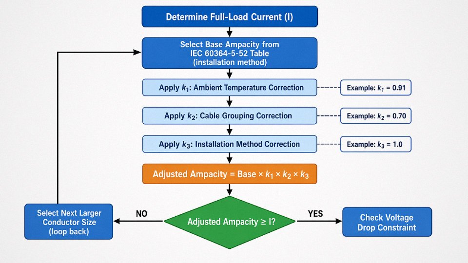
IEC 60364-5-52 provides base ampacity tables organized by installation method — clipped direct, in conduit, on a perforated tray, buried, and so on. A 4 mm² copper conductor in free air carries roughly 36–41 A depending on method and ambient; that range exists for a reason, and you should never just grab the high end.
From that base figure you multiply three correction factors:
k₁ corrects for ambient temperature. At 40°C instead of the reference 30°C, a PVC cable’s k₁ runs around 0.87; XLPE fares somewhat better at roughly 0.91 because its temperature headroom is larger.
k₂ corrects for cable grouping. Three single-core cables touching in a conduit might give you k₂ ≈ 0.70. Twelve cables bunched in a tray can drop that to 0.50 or below. This is the factor most commonly ignored in panel shops, in my experience.
k₃ accounts for installation method deviations from the base case — embedded in insulation, for instance, or under a raised floor with restricted airflow. Values range roughly 0.70–1.00.
Multiply them all: Adjusted ampacity = Base ampacity × k₁ × k₂ × k₃.
Worked Example: Sizing for a 30 kW Motor
A 3-phase, 400 V, 30 kW motor at 0.85 power factor and 92% efficiency draws a full-load current of roughly:
I = 30,000 / (√3 × 400 × 0.85 × 0.92) ≈ 54 A
Environment: 40°C ambient, three cables in a PVC conduit. From IEC 60364-5-52, a 10 mm² copper XLPE cable in conduit has a base ampacity of about 57 A. Apply k₁ = 0.91 (40°C, XLPE), k₂ = 0.70 (three cables grouped), k₃ = 1.0: adjusted ampacity = 57 × 0.91 × 0.70 ≈ 36 A. That fails. Moving to 16 mm² copper — base ampacity roughly 76 A in conduit — gives 76 × 0.91 × 0.70 ≈ 48 A. Still tight for 54 A, so you step to the next size or revisit the conduit fill. In practice, most engineers land on 16 mm² by also renegotiating the conduit layout to reduce grouping. The takeaway: derating can eliminate two or three standard size steps.
When Voltage Drop Governs Instead of Ampacity
On long runs — typically anything beyond 100–150 m at low voltage — voltage drop often becomes the binding constraint before ampacity does. The formula:
ΔV = (√3 × I × L × (R·cosφ + X·sinφ)) / 1000
where R and X are conductor resistance and reactance per km, L is length in meters, and current I in amps. Most standards allow a maximum 3–5% voltage drop from supply point to load terminals; IEC 60364 and local codes vary, so check the applicable one. A 54 A load running 200 m on 16 mm² copper can easily produce a 6–7% drop depending on the conductor’s actual resistance at operating temperature — enough to cause contactors to chatter and motor torque to sag noticeably. Upsizing to 25 mm² for the run length, not for current, is the right answer. Procurement managers sometimes push back on this because the cable looks “oversized on the datasheet.” It isn’t.
Short-Circuit Rating: The Check That Gets Omitted
Even a properly sized cable for normal operation can be destroyed in seconds if fault current exceeds what the conductor cross-section can absorb before the protective device clears. The adiabatic equation:
S = I_sc × √t / k
where S is cross-section in mm², I_sc is prospective fault current in amps, t is the protective device’s clearing time in seconds, and k is a material constant (roughly 143 for copper/PVC, 176 for copper/XLPE). If your switchboard has a prospective fault level of 16 kA and the upstream breaker clears in 0.1 s, the minimum conductor size works out to about 28 mm² for copper/XLPE. A 16 mm² cable would not survive — it would fail adiabatically before the breaker opens. This is non-negotiable verification, not an optional step.
Aluminum conductors require approximately 1.6 times the cross-section of copper to carry equivalent current.True
This follows directly from the ratio of resistivities: aluminum at 2.82 × 10⁻⁸ Ω·m versus copper at 1.72 × 10⁻⁸ Ω·m, adjusted for the standard cross-section increments available in IEC 60228 conductor classes.
Aluminum vs. Copper: Where the Economics Actually Shift
Aluminum’s resistivity disadvantage means a 95 mm² aluminum conductor roughly matches a 70 mm² copper conductor for ampacity — and aluminum also requires more robust terminations and anti-oxidant compound at joints. Below about 50 mm², the weight and cost savings rarely justify the termination complexity and the risk of connection degradation over time, especially in humid or industrial environments. Above 50–70 mm², the economics shift: aluminum cable can cost 40–60% less per meter depending on copper market pricing at the time of procurement, which on a large industrial facility or infrastructure project translates into real money. The decision isn’t about one cable run; it’s about total installed cost including lugs, termination labor, and the maintenance discipline your plant actually has.
Insulation and Sheathing Materials: XLPE, PVC, EPR, and When Each Is the Right Choice
The cable datasheets all look similar until a conductor runs at 85°C ambient in a tunnel full of commuters, or gets buried under a chemical plant’s drainage ditch. That’s when insulation choice stops being a spec-sheet exercise.
PVC: The Default That Earns Its Place — Up to a Point
PVC insulation is cheap, widely stocked, and chemically resistant to most dilute acids and alkalis you’ll find in a normal industrial environment. It handles general indoor fixed wiring well, and for the bulk of low-voltage building installations — which account for roughly 60–70% of all wiring worldwide — it does exactly what’s needed without overengineering the cost.
The limits are real, though. Maximum continuous conductor temperature is 70°C. Push beyond that and the plasticizer migrates, the insulation becomes brittle over time, and you’re looking at premature failure in 8–12 years instead of the 25–30 years a properly loaded XLPE cable can deliver. In cold climates or refrigerated warehouses running below -15°C, PVC stiffens badly — it can crack during installation if a cable gets dragged around a tight bend in a -20°C freezer corridor, something I’ve seen cause a rework job that cost three times the original cable savings.
The harder issue: PVC releases hydrogen chloride gas in a fire. In an open outdoor substation, that’s manageable. In a confined space — a cable basement, a passenger train, a data center — it’s a life-safety problem. Know your environment before defaulting to PVC.
XLPE: The Thermal Workhorse for Anything That Runs Hot or High-Voltage
Cross-linked polyethylene bumps the continuous rating to 90°C and handles short-circuit excursions up to 250°C without the insulation collapsing onto the conductor. That extra 20°C headroom over PVC translates directly into smaller conductor cross-sections for the same current, or more thermal margin when installation conditions are worse than ideal — cables grouped in a tray, ambient temperature above 30°C, or both.
XLPE insulation allows cables to carry more current than equivalently sized PVC-insulated cables at the same ambient temperature.True
Higher maximum conductor temperature (90°C vs 70°C) means ampacity tables permit greater current for XLPE, all else being equal. IEC 60502 tables reflect this difference explicitly.
XLPE also has lower dielectric losses than PVC — matters less at 400 V, matters quite a lot in medium-voltage cables running at 6–35 kV where dielectric heating is non-trivial. It’s the standard choice for MV distribution, virtually all HV transmission cables, and any installation where the thermal budget is tight.
EPR: When Flexibility and Environment Trump Everything Else
Ethylene propylene rubber stays flexible down to -40°C, which is why it dominates shipboard cabling, offshore platform installations, and mining equipment leads where cables get flexed, coiled, and dragged in conditions that would embrittle XLPE. Its ozone and UV resistance is genuinely superior — outdoor installations where cables are exposed rather than conduit-protected benefit from EPR’s weathering performance over a long service life. Continuous temperature rating matches XLPE at 90°C. It costs more per meter than either PVC or XLPE, typically 20–40% more depending on cross-section and market conditions, so it’s not the right call for a simple indoor fixed installation.
LSZH Sheathing: Not Optional in Occupied Enclosed Spaces
Low Smoke Zero Halogen compound doesn’t insulate the conductor — it’s the outer sheath material. What it does is burn without producing the dense black smoke and halogen acids that kill people trying to evacuate a tunnel or metro station. IEC 60332 flame-retardant testing (particularly the IEC 60332-3 category A/B/C bundle tests) is the compliance benchmark to ask suppliers for, not just a generic “flame retardant” claim. Many cable suppliers mark PVC cables as flame retardant — that satisfies IEC 60332-1 single-cable testing but fails the bundle test. Confirm which test was passed.
In practice, any cable running through a metro station, airport terminal, hospital corridor, or enclosed public building should spec LSZH sheath as a baseline, full stop.
Outer Sheath Selection by Installation Environment
The insulation protects the conductor. The outer sheath protects the insulation.
Standard PVC sheath handles most indoor and sheltered outdoor runs. For direct burial, polyethylene sheath provides a meaningful moisture barrier that PVC — which is slightly permeable over decades — doesn’t match well. HDPE oversheath is used on cables pulled through conduit in abrasive ground conditions; it handles repeated mechanical contact without wear-through the way softer compounds can’t. For industrial plants with hydraulic oil, cutting fluids, or solvent splash exposure, CSP (chlorosulphonated polyethylene) or CPE (chlorinated polyethylene) sheaths hold up where standard PVC will swell and degrade within a few years.
Decision Matrix: Environment to Insulation and Sheath
| Installation Environment | Recommended Insulation | Recommended Outer Sheath | Key Standard Reference |
|---|---|---|---|
| Indoor dry, general fixed wiring | PVC | PVC | IEC 60502-1 |
| Outdoor, UV-exposed, above ground | XLPE or EPR | UV-stabilized PE or EPR | IEC 60502-1 |
| Direct burial, no conduit | XLPE | PE or HDPE + armor | IEC 60502-2 |
| Submerged / wet duct | XLPE | PE with longitudinal water block | IEC 60502-2 |
| High-temperature industrial (>70°C ambient zone) | XLPE | CSP or XLPE sheath | IEC 60502 |
| Fire-sensitive: tunnels, metros, public buildings | XLPE or EPR | LSZH | IEC 60332-3 |
| Shipboard / offshore / mining | EPR | CSP or LSZH-EPR | IEC 60092 / IEC 60079 |
| Chemical plant, oil/solvent exposure | EPR or XLPE | CPE or CSP | Site-specific plus IEC 60502 |
The matrix won’t replace a site survey, but it eliminates the obviously wrong choices fast — which is usually what procurement needs at the early spec stage.
Armor, Shielding, and Mechanical Protection: Choosing the Right Cable Construction for the Installation Environment
The insulation rating and conductor size get most of the attention during cable selection, but the construction — armor type, shielding layer, overall jacket — is what determines whether the cable actually survives its installation environment for 20-plus years. Get this wrong and you’re looking at insulation abrasion, ground faults, or a complete cable replacement pull within the first few years of operation.
When Armor Is Actually Necessary
Not every cable run needs armor, and specifying it where it isn’t needed adds cost without adding value. But certain environments make armoring non-negotiable.
Direct burial is the clearest case. A cable laid in a trench — even with sand bedding and warning tape — faces soil settlement, rodent attack, and occasional excavation damage. On factory floors with active forklift traffic, an unarmored cable in a surface conduit is genuinely at risk; a misplaced pallet jack can crush standard rigid conduit, and whatever is inside it. Cable trays in process plants (refineries, chemical plants, paper mills) expose cables to falling tools, foot traffic during maintenance, and occasionally chemical spillage that degrades unarmored PVC jackets faster than expected.
A useful rough rule: if the cable route passes through any zone where you cannot guarantee controlled access, armor the cable.
SWA vs. AWA — The Choice Matters More on Single-Core Runs
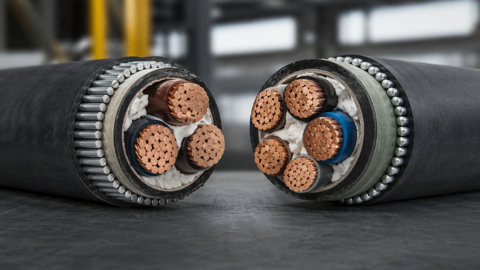
Steel wire armor (SWA) is the workhorse for multicore power cables. It handles both radial crush loads and longitudinal tension, which is what you need for long vertical drops or direct-burial runs on slopes. Heavy-duty SWA grades can resist crush loads up to roughly 6,500 N/cm — enough to handle most realistic mechanical hazards in a plant environment.
Steel wire armor in heavy-duty cable grades can withstand crush resistance up to approximately 6,500 N/cm.True
This figure is consistent with IEC 60502-1 and manufacturer test data for heavy-duty SWA cable constructions; actual values vary by wire diameter and lay configuration.
Aluminum wire armor (AWA) is lighter — typically 20–30% lighter than equivalent SWA, depending on conductor cross-section — and mechanically adequate for most burial and tray applications. The critical reason to specify AWA on single-core cables is magnetic: a steel armor forming a closed magnetic circuit around a single AC conductor generates eddy currents and hysteresis losses that can cause measurable heating and efficiency loss, especially above 150 A or so. AWA is non-magnetic and sidesteps this entirely. On three-core cables the magnetic fields largely cancel, so SWA is fine.
Steel Tape Armor for Radial Protection
Steel tape armor (STA) and double steel tape armor (DSTA) serve a different mechanical role. They resist radial crushing but offer limited tensile strength. That makes them well-suited for submarine distribution cables and direct-burial feeders in relatively flat, stable ground where the main threat is point loading rather than longitudinal stress. DSTA is common in medium-voltage distribution cables where you want the extra radial protection without the weight penalty of wire armor.
EMI Shielding on VFD Output Cables and Instrumentation-Adjacent Runs
Variable-frequency drives chop the supply voltage at switching frequencies typically between 2 and 16 kHz, and the output cable radiates this noise aggressively if unshielded. IEC 61800-3 explicitly requires shielded cable on VFD output runs in residential and light-industrial environments — and in practice, most process plant electrical engineers specify it everywhere regardless of category, because the cost of a shielded cable is far lower than troubleshooting ghost faults on nearby instrumentation loops.
For VFD cables, copper braid shielding gives the most consistent coverage (typically 85–95% optical coverage) and handles the high-frequency noise spectrum better than copper tape alone. Copper tape is adequate for lower-frequency interference and is cheaper, but the tape seam creates a coverage gap that braid does not. Wire screen sits between the two — reasonable coverage, more flexible than tape, used often on medium-voltage instrumentation-adjacent runs. For most VFD applications in process plants, specify a cable with both a copper braid shield and a low-impedance bonding path at both ends. Floating one end of the shield on a VFD cable is a common mistake that leaves common-mode noise with nowhere to go.
Conduit vs. Armored Cable: Total Installed Cost Logic
The comparison people usually miss is installed cost, not supply cost. Armored cable has a higher unit price — roughly 15–30% more than unarmored equivalent, depending on armor type and cable size — but it eliminates the conduit, conduit fittings, conduit supports, and the labor to install them.
On short runs under about 30–50 m with multiple cable changes in the same tray, unarmored cable in PVC conduit often wins on total cost because the conduit infrastructure is shared across many circuits. On long dedicated runs — a single feeder from the MCC to a remote pump station 200 m away, say — armored cable typically comes out cheaper once you price the conduit route end to end. In outdoor or underground installations, the arithmetic almost always favors armored cable.
Bending Radius: The Constraint That Bites During Installation
Armored cables are stiffer than unarmored, and the minimum bend radius requirements reflect this. As a working rule, armored cables require a minimum bend radius of 12–15 times the overall cable diameter during installation — check the specific manufacturer data, because DSTA and large cross-section cables can require the higher end of that range. In practice this becomes a real constraint in congested trunking, around tight bends in cable trays, or in switchroom cable entry zones where multiple large armored cables have to be routed through limited space. A 50 mm² four-core SWA cable might have an overall diameter of 35–40 mm, putting the minimum bend radius at 420–600 mm. Trying to force it tighter will crack the armor wires or deform the insulation — neither of which is visible until the cable fails under load.
Plan the cable route geometry before you finalize armor specification. Sometimes the right answer in a congested layout is a more flexible unarmored cable in a protected steel duct rather than an armored cable you cannot actually bend into the space available.
Environmental and Special-Application Cables: Oil, Heat, Cold, UV, and Submersion Requirements
Standard catalog cables handle standard conditions. The trouble is, a surprising share of real industrial installations aren’t standard — and the cost of finding that out after commissioning is ugly.
Oil-Resistant Cables
In oil refineries, petrochemical processing, and on mobile machinery like hydraulic presses and mining excavators, cable sheaths face continuous exposure to mineral oils, hydraulic fluids, and fuel splatter. Standard PVC softens and swells when it contacts these substances. The plasticizers leach out, the sheath cracks, and eventually the insulation underneath is exposed.
Three sheath materials actually hold up here: oil-resistant PVC (sometimes called Type 2 PVC per IEC 60811-404 immersion testing), chlorosulfonated polyethylene (CSP, sold under various trade names), and nitrile rubber. Oil-resistant PVC is the cheapest entry point and adequate for incidental splash contact — say, a factory floor where oils drip occasionally. CSP handles more sustained chemical exposure and also resists ozone, making it common on outdoor refinery cable trays. Nitrile rubber is the heaviest-duty option: it’s the compound you specify for drag chains, festoon systems, and any cable that sits in pooled hydraulic fluid. The cost delta between standard PVC and nitrile rubber sheathing runs roughly 40–80% premium depending on conductor cross-section and order volume.
IEC 60811-404 tests oil-resistant cable sheaths by immersing samples in IRM 902 reference oil at elevated temperature and measuring tensile strength and elongation retention.True
IEC 60811-404 is the internationally recognized test method for evaluating the oil resistance of cable sheaths and insulation, using standardized reference oils and temperature-controlled immersion to quantify mechanical property retention.
High-Temperature Cable Constructions
Furnace wiring, industrial oven interiors, and foundry floor installations regularly see ambient temperatures that will simply destroy any XLPE or standard PVC cable within months — sometimes weeks. Above roughly 125°C continuous, silicone rubber insulation (rated to 180°C continuous, with short-term tolerance often higher) becomes the practical minimum. Above 200°C, glass-fiber braided constructions with mica tape barriers handle up to 300°C or beyond in certain configurations. These aren’t exotic products; they’re just routinely under-specified because the catalog starts with XLPE.
One thing worth watching: silicone rubber is mechanically soft and tears easily during installation. In practice it needs to be routed through conduit or at minimum protected from abrasion, or the thermal rating becomes irrelevant.
Cold-Temperature Applications
Wind turbines in Scandinavia and Canada, cold-storage warehouses running at -30°C, and any polar infrastructure present the opposite problem. Standard PVC becomes brittle below roughly -15°C and will crack if the cable is bent during installation or maintenance. You need insulation and sheath compounds with a glass transition temperature (Tg) below -40°C. EPR (ethylene propylene rubber) is the go-to, and several cold-flex PVC grades formulated with specific plasticizer packages also qualify — though confirming the actual Tg value with the manufacturer matters more than the product name.
UV and Outdoor Exposure
Any cable running outdoors in direct sunlight for more than five or so years needs deliberate UV stabilization. Carbon-black-loaded PVC and black HDPE sheaths provide this through the UV-absorbing properties of the carbon black itself. Standard un-pigmented or lightly colored sheaths do not. UV resistance should be confirmed against IEC 60811-405 test results, not assumed from color alone.
Submersion and Direct Burial
Wet ducts and direct-burial installations without conduit expose cables to longitudinal water migration — water that works its way along the conductor strands and insulation interfaces over time, eventually causing insulation breakdown and corrosion. The solution is water-blocking: either water-swellable powder applied between strands, water-swellable tape wrapped around the conductor assembly, or a combination of both. IEC 60502-2 specifies the water penetration test for medium-voltage cables in these conditions, and any cable being quoted for direct burial should carry explicit compliance.
Matching Specialized Environments to the Right Product Family
Jinda’s product range covers several of the demanding environments described above. Solar DC cables (built to IEC 62930 / EN 50618) use irradiation-crosslinked insulation to handle the UV exposure, temperature cycling, and physical installation demands of utility-scale and rooftop PV systems. Wind turbine torsion-flex cables are engineered specifically for the continuous torsional movement inside turbine towers — standard cables fatigue and fail at the conductor level within a relatively short service period under those conditions. For offshore and coastal platform installations, Jinda produces cables with mud-resistant, seawater-resistant sheaths and armoring configurations suited to the corrosive marine environment.
The right cable for a harsh environment isn’t always dramatically more expensive than a standard one. What is expensive is discovering the mismatch after installation.
International Standards and Certification Marks: What the Labels on the Cable Drum Actually Mean
Walk into any cable warehouse and you’ll find drums stacked with markings that look authoritative but mean very different things depending on where the cable is going, who certified it, and whether that certification was third-party verified or simply self-declared by the manufacturer. Getting this wrong doesn’t show up immediately — it shows up eighteen months later when an insurer voids a claim, or a job-site inspection fails, or a fire classification audit reveals the installed product never actually met the specified CPR class.
The Major Standards Families and Where Each Applies
IEC standards — primarily IEC 60502 for medium and low-voltage power cables and IEC 60228 for conductor classes — function as the global engineering baseline. Most international procurement specs reference IEC because it creates a common technical language between a buyer in Southeast Asia, a manufacturer in China, and an engineering firm in the Netherlands. That said, “IEC-compliant” on a data sheet means nothing by itself unless test reports back it up.
BS 6346 and BS 7846 remain relevant for the UK and significant portions of former Commonwealth markets — parts of sub-Saharan Africa, the Middle East, and South Asia still specify BS cable construction for legacy infrastructure projects. VDE approval (issued by the German testing institute of the same name) carries unusually strong weight in EU industrial procurement; European plant engineers and procurement managers often treat VDE-certified cable as a premium tier, partly for justified technical reasons and partly because of longstanding buying habits.
UL listing governs North American installations almost exclusively. If a cable isn’t UL-listed and you’re installing it in the US or supplying it to a US contractor, expect it to be rejected at inspection — full stop. CSA certification covers Canada with similar force. AS/NZS standards govern Australia and New Zealand and have enough unique construction requirements (particularly around flame performance) that you can’t simply ship IEC cable and assume it passes.
GB standards are China’s national specifications. For domestic Chinese projects they’re mandatory. For export projects, GB-only testing is usually insufficient unless the destination country explicitly accepts it, which most don’t.
CPR, CE Marking, and EU Fire Classification
The EU’s Construction Products Regulation (CPR) changed the cable procurement landscape in Europe significantly. Any cable for fixed installation in a building in the EU must carry a Declaration of Performance (DoP) and a CPR fire classification — running from Aca (best, essentially non-combustible) down through B1ca, B2ca, Cca, Dca, Eca, to Fca (essentially unclassified). The classification determines where a cable can legally be installed: Dca is commonly required in commercial buildings, Cca in escape routes, B2ca or better in high-rise structures.
CE marking on a cable drum without the accompanying DoP document is meaningless. Insist on the DoP. It will state the declared performance values, the notified body that assessed it, and the specific product it applies to.
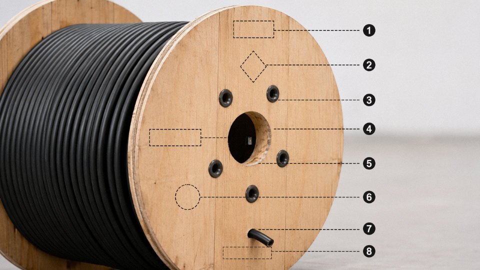
Self-Declaration vs. Third-Party Certification
This is where procurement gets genuinely consequential. A manufacturer’s own test report says: “we tested our cable and it passed.” A KEMA certificate, a BASEC approval, or a UL listing says: “an independent body tested this cable type against the specified standard and confirmed compliance.” The distinction matters most for fire performance and short-circuit ratings, where the consequences of failure are severe and the temptation to present borderline results favorably is real.
In practice, third-party certification costs manufacturers time and money, which is precisely why it carries signal value. When specifying cables for critical infrastructure, data centers, hospitals, or any facility subject to regulatory inspection, require third-party certified product and ask for the certificate number — then look it up on the issuing body’s public database. Most of them maintain searchable online registers.
Decoding the Sheath Marking String
A typical marking printed on the outer sheath reads something like:
3×16 mm² XLPE/SWA/PVC 0.6/1 kV IEC 60502-1
Breaking that down:
| Field | What It Means |
|---|---|
| 3×16 mm² | Three conductors, each 16 mm² cross-section |
| XLPE | Cross-linked polyethylene insulation on individual conductors |
| SWA | Steel wire armour mechanical protection layer |
| PVC | Outer sheath material |
| 0.6/1 kV | Rated voltage: 0.6 kV conductor-to-earth, 1 kV conductor-to-conductor |
| IEC 60502-1 | Construction and test standard governing this cable |
If the drum you receive shows PVC/SWA/PVC but you specified XLPE insulation, you’re looking at a cable with a 70°C conductor temperature limit instead of 90°C — your ampacity calculations are now wrong, and depending on ambient conditions and installation method, the cable may be running chronically over-temperature from day one.
RoHS and REACH: The Chemical Compliance Layer
For any cable installed or sold into the EU, RoHS and REACH are not optional. RoHS restricts lead stabilizers in PVC insulation and sheathing — historically common in cable manufacturing — along with specific phthalate plasticizers. REACH addresses hexavalent chromium compounds sometimes present in zinc-chromate primers on steel armor wires. Cables manufactured without attention to these restrictions will fail EU customs documentation checks or trigger liability under CE compliance audits.
Legitimate manufacturers maintain substance declaration documentation per IEC 62321 test methods. Ask for it. If a supplier hesitates or provides a generic letter rather than substance-specific test data, that’s a red flag.
Verifying Jinda’s Certification Portfolio
Jinda holds ISO 9001 quality management and ISO 14001 environmental management certifications, with product-level certifications covering IEC, CE/CPR, and export-market standards.True
These certifications are maintained across Jinda's production facilities and are verifiable through the respective issuing bodies upon buyer request.
For any specific cable type — say, a medium-voltage XLPE/SWA cable for a European infrastructure project — Jinda’s technical team can provide the relevant IEC 60502 type test reports, CPR DoP documentation, and conductor class verification per IEC 60228. The practical step for procurement managers is straightforward: specify the exact cable construction and destination market in the RFQ, request the corresponding certificate numbers and DoP references, and cross-check them before issuing a purchase order. That thirty-minute verification step has saved more than a few projects from a very expensive re-pull.
Procurement Checklist: Specification Data Every Supplier Needs Before Quoting
Incomplete specifications are the single biggest source of quoting errors in cable procurement. A supplier receiving a vague inquiry — “4-core, 95 mm², 100 meters” — will default to whatever interpretation minimizes their cost, not yours. That means PVC insulation when your tunnel needs LSZH, unarmored construction when your trench has vehicle crossings, or aluminum conductors when your termination hardware is rated for copper only. Getting the spec right before you send the RFQ compresses lead time, eliminates substitution disputes, and gives you an apples-to-apples comparison across multiple suppliers.
The 12 Points That Define a Quotable Specification
1. System voltage U₀/U. State both values explicitly — U₀ is the conductor-to-earth voltage, U is conductor-to-conductor. A cable marked 0.6/1 kV is not interchangeable with one marked 1.8/3 kV, even if the conductors are identical. Misquoting this gets you the wrong insulation wall thickness.
2. Rated current and load profile. Nameplate current matters, but so does whether the load is continuous, cyclic, or intermittent. A motor that runs at full load for 20 minutes then idles for 40 needs a different thermal assessment than a continuous-duty pump. Tell the supplier both the peak current and the duty cycle.
3. Number of cores and conductor cross-section. Be explicit: “3-core + 1 reduced neutral” is not the same as “4-core equal section.” Specify the cross-section in mm² per core.
4. Conductor material. Copper or aluminum — state it. Copper’s resistivity (~1.72 × 10⁻⁸ Ω·m at 20°C) versus aluminum’s (~2.82 × 10⁻⁸ Ω·m) means an aluminum cable needs roughly 1.6× the cross-section for equivalent resistance. If your project assumes copper pricing and a supplier quotes aluminum, your cost comparison is meaningless.
5. Insulation type. XLPE, PVC, EPR — each covered in an earlier section of this guide. Write it down explicitly. XLPE’s 90°C continuous rating versus PVC’s 70°C ceiling is a real ampacity difference, not a minor footnote.
6. Sheath type. PVC, LSZH, or polyurethane for flexible applications. For any occupied building or confined space, LSZH is often a code requirement, not a preference.
7. Armor type if required. SWA (steel wire armor), AWA (aluminum wire armor), or STA (steel tape armor). Specify the bedding and outer sheath material too — a bare SWA drum sitting in a marine atmosphere for six months will tell you why this matters.
8. Special environmental requirements. Oil resistance, UV stabilization, low-temperature flexibility down to −40°C, submersion rating, flame propagation class (IEC 60332 categories). If it applies to your site, write it in the spec.
9. Applicable standard and certification. IEC 60502, BS 5467, NF C 32-321, or whichever standard governs your project. Some markets require third-party certification marks; others accept a manufacturer’s self-declaration against the standard. Know which applies before you quote.
10. Installation method. Direct burial, duct, cable tray, free air, or underwater. Current-carrying capacity can vary by 20–35% depending on installation method and grouping — suppliers need this to confirm the cable is adequate, not just correctly specified on paper.
11. Total length per drum and packaging preference. Standard LV drum lengths run 500 m or 1,000 m; MV cables typically ship on 100–500 m drums depending on conductor size and cable weight. Ordering non-standard lengths almost always adds cost and 1–3 weeks to lead time. For large projects, scheduling drum cuts early — aligning run lengths to actual circuit lengths — avoids paying for jointing labor to use up awkward offcuts.
12. Delivery country and import certification requirements. This one gets overlooked until the cable is sitting at customs. Wooden drums for export must comply with ISPM 15 (heat treatment or fumigation with a marked stamp). Sea freight drums need moisture-sealed ends to prevent ingress during multi-week transits, especially through tropical routes. Large MV cable drums can weigh 8–15 tonnes; confirm container floor load ratings with your freight forwarder before packing.
Factory Acceptance Testing: Don’t Skip This for Critical Projects
Routine tests — conductor DC resistance per IEC 60228, insulation resistance, and AC high-voltage withstand — should be standard on any order. For critical infrastructure, substation feeders, or any project where a cable failure means plant shutdown rather than just a maintenance call, specify witnessed FAT in the purchase order before production starts, not after. Type test reports (confirming the design was validated, not just a specific drum) are acceptable for standard products. Special tests — partial discharge, sheath integrity after installation simulation, fire performance — depend on the application and are worth the cost when downtime exposure is high.
Jinda provides a compliant cable specification and quotation within 48 hours for standard products when customers submit complete project parameters.True
This is a stated manufacturer capability for their standard product range, conditional on complete input data being provided upfront — an achievable turnaround for a manufacturer with five production bases and dedicated technical pre-sales support.
Jinda’s technical pre-sales team works directly with engineers and procurement managers to translate project parameters into a fully compliant cable specification. Submit voltage class, load data, installation environment, applicable standard, and quantity — the team returns a specification and commercial quotation within 48 hours for standard products. For non-standard constructions, an initial technical review typically takes 2–4 working days before a formal quote is issued. That process only works if the input is complete. Use this checklist.
Frequently Asked Questions About Buying Power Cables

Can I use a cable rated for a higher voltage than my system requires?
Electrically, yes — always. A 6/10 kV cable running on a 400 V system is perfectly safe. The insulation wall is just thicker than necessary, which means a slightly heavier, stiffer cable and a cost premium you probably don’t need. The only time deliberately over-specifying voltage class makes sense is when a future upgrade is already planned or when you’re running through a conduit that would be nearly impossible to re-pull. For a straightforward 0.6/1 kV industrial installation, buying MV cable to do the job is a waste of budget.
Is aluminum cable as reliable as copper for industrial use?
Yes — with two conditions met. First, size it correctly: aluminum’s resistivity is roughly 2.82 × 10⁻⁸ Ω·m versus 1.72 × 10⁻⁸ Ω·m for copper, which means you need approximately 1.6× the cross-sectional area to carry the same current. A 95 mm² aluminum conductor is the practical equivalent of a 70 mm² copper one for most feeder applications. Second, use aluminum-rated lugs and apply anti-oxidant jointing compound at every termination — skipping this step is how aluminum gets its (somewhat unfair) bad reputation. Aluminum oxide forms quickly on exposed conductor surfaces and drives up contact resistance, which leads to hot terminations, then loose connections, then arc faults. Get the termination right and aluminum is standard practice for distribution feeders above 50 mm² across large parts of Europe, the Middle East, and North America. It’s lighter and cheaper per meter. On a long overhead or underground feeder run, that matters.
Flexible vs. fixed-wiring cable — can I substitute one for the other?
These serve genuinely different purposes. Flexible cables (IEC 60228 Class 5 or 6) use fine stranding specifically engineered for repeated bending — machine tool leads, portable equipment, trailing cables. Fixed-wiring cables (Class 1 solid or Class 2 stranded) are optimized for permanent installation where movement after commissioning is minimal.
Using a flexible cable as permanent fixed wiring is generally permitted and sometimes convenient. The reverse is not. Put a Class 2 or solid conductor where repeated flexing occurs and you’ll see conductor fatigue cracking within months, depending on bend radius and cycle frequency. The failure mode is insidious — the outer insulation looks fine while the conductor is fractured internally, raising resistance and generating heat. Don’t do it.
Using a rigid fixed-wiring cable in a dynamic flexing application causes internal conductor fatigue that is invisible from outside the insulation until the cable fails.True
Repeated bending of large-strand or solid conductors beyond their rated flex life causes work-hardening and micro-fractures in the copper strands. Resistance rises locally, heat builds, and eventual open-circuit or arcing failure follows — all while the outer sheath appears undamaged.
How do I verify a supplier’s quality before placing a bulk order?
Ask for the ISO 9001 certificate and check the issuing body — it should be an accredited certification body, not a house-brand document. More importantly, request type test reports for the specific cable construction you’re buying, issued by a recognized third-party lab. Any credible manufacturer can produce these without hesitation. If there’s stalling or vague references to “internal testing,” that’s a signal.
A factory audit is worth the cost on orders above a certain threshold — roughly, whenever the cable represents a critical path item in your project. Ask for references from buyers in your country or your industry sector specifically, because installation environment and regulatory context vary enough that a reference from a completely different market tells you less than you might hope.
Lead times for custom or large-quantity orders from China?
Standard LV constructions in common sizes typically ship within 15–25 days ex-factory, give or take, depending on current production loading. MV cables with special constructions, third-party witnessed tests, or specific national certifications require more time — 30–60 days is realistic, and some certification processes add further delays that are outside the factory’s control. Budget an additional 20–45 days for sea freight transit to Europe, the Middle East, or East Africa. Tighter vessel schedules and port congestion in certain seasons can push that toward the higher end. If your project has a hard commissioning date, start procurement earlier than feels necessary.
How do I calculate meters on a drum from drum dimensions?
The working approximation most cable engineers use:
L = π × (D² − d²) × W / (4 × c)
Where D is the flange outer diameter, d is the barrel diameter, W is the traverse width between flanges, and c is the approximate cross-sectional area of the cable itself (diameter squared). All dimensions in consistent units. It’s an estimate — winding tension and layer alignment affect the real figure by a few percent — so reputable manufacturers publish exact drum-fill data in their catalogs. Use the formula as a sanity check, not as the number you order by.
What does ‘concentric neutral’ cable mean, and when is it needed?
A concentric neutral cable wraps individual copper wires helically around the outer insulation layer, forming both the neutral return conductor and an electrostatic ground shield in a single layer. It’s the standard construction for underground residential distribution (URD) systems across North America and appears in similar direct-burial medium-voltage networks elsewhere. The design eliminates the need for a separate ground conductor in the trench, simplifies installation, and provides a consistent shield for cable system protection. If your project involves direct-buried MV distribution in a North American-standard grid, concentric neutral is likely what your utility specification requires — and substituting a screened cable with a separate neutral without checking is the kind of discrepancy that causes acceptance failures at energization.