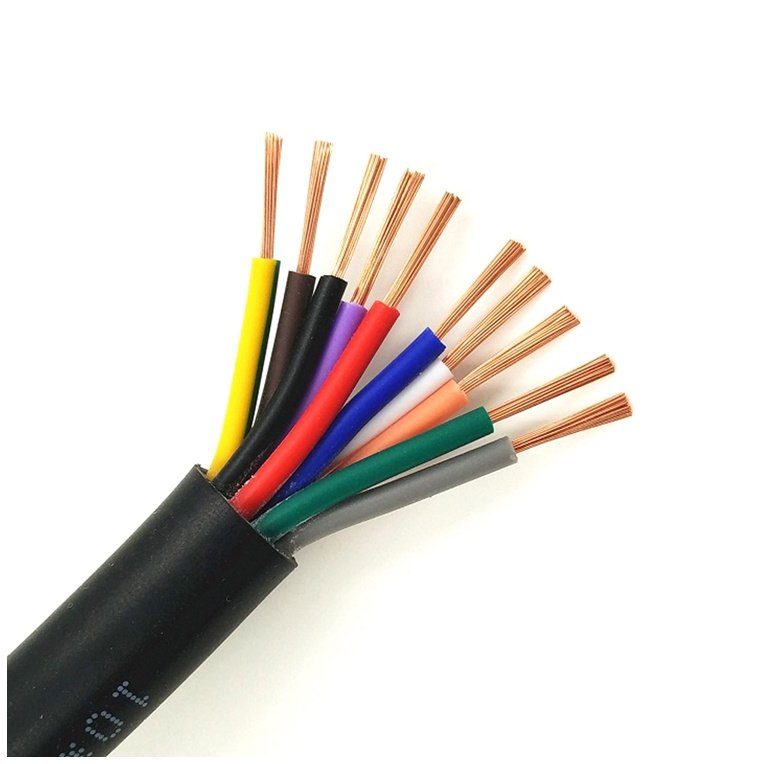
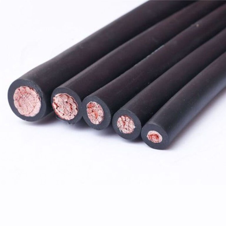
Procurement teams ordering replacement conductor without knowing which wire type is actually strung on a given span routinely end up with stock that either can’t carry the mechanical load or won’t fit existing hardware — and a line that stays out of service while someone scrambles to reorder. Maintenance crews who can’t identify a ground wire versus a neutral versus a phase conductor by sight have started re-energizing lines with the wrong terminations in place. The financial hit from a single unplanned outage on a distribution feeder runs into the tens of thousands of dollars per hour depending on load density; on a transmission corridor the consequences scale up fast. Understanding what each wire on a power line actually does, physically and electrically, is the baseline competency before any specification, procurement, or field decision gets made.
Power lines carry several distinct wire types, each with a different function: phase conductors carry the actual current (typically aluminum-based, often ACSR), a neutral conductor provides a return path on distribution systems, and one or two shield wires (also called ground wires) run at the top of the structure to intercept lightning before it hits the energized conductors. Distribution lines generally operate between 4 kV and 35 kV using a 3-phase 4-wire arrangement, while high-voltage transmission lines run from roughly 115 kV up to 765 kV on a 3-phase 3-wire configuration with no neutral at all.
What makes this more layered in practice is that modern lines can add optical ground wires (OPGW), bundled sub-conductors at transmission voltage, and bare versus covered configurations at distribution voltage — all of which look superficially similar from the ground or from a specification sheet, but behave very differently under load, fault conditions, and mechanical tension. The wiring arrangement overhead tells a surprisingly complete story about the system it serves, if you know what to look for.
Phase Conductors: The Live Wires That Actually Carry Electrical Power
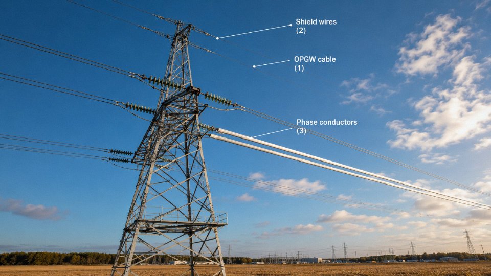
Phase conductors are the reason the tower exists. Everything else on a power line — ground wires, optical cables, hardware — serves a supporting role. Phase conductors carry the actual current at full system voltage, and on any standard 3-phase AC network, there are always three of them. That’s non-negotiable whether you’re running a 115 kV subtransmission feeder through flat farmland or a 500 kV bulk transmission corridor across mountain terrain.
The physical arrangement of those three phases depends on tower geometry. Flat configurations spread all three conductors horizontally across a crossarm and are common on lattice towers where right-of-way is wide. Vertical configurations stack them one above another on a single pole, which suits narrower corridors and is typical in distribution. Delta arrangements — a triangle pattern — split the difference and show up frequently on double-circuit towers where compactness matters. Electrically, the arrangement is less critical than maintaining correct phase-to-phase and phase-to-ground clearances; mechanically, it affects unbalanced loading and tower moment calculations significantly.
Conductor Families: Materials Drive the Trade-Off
ACSR (aluminum conductor, steel-reinforced) is still the workhorse. Roughly 50–60% of global overhead transmission installations use it, and for good reason: the steel core carries the mechanical load while the outer aluminum strands handle conductivity. It’s a practical split of labor that has held up for over a century. The downside is thermal elongation — under heavy load, the aluminum strands heat up and the conductor sags, which limits ampacity in warm climates or constrains span length.
AAC, all-aluminum conductor, has no steel core at all. That makes it lighter and gives it better conductivity per unit weight, but tensile strength suffers. In practice, AAC suits short, heavily loaded urban distribution spans where sag and tension are managed by structure spacing, not conductor stiffness. Long rural spans? AAC is the wrong tool.
AAAC swaps in an aluminum-magnesium-silicon alloy, typically 6201 series. The alloy improves strength over pure aluminum without adding steel, and corrosion resistance is noticeably better — a real advantage in coastal substations or industrial environments where salt fog or sulfur compounds attack conventional ACSR over time. If you’re specifying conductors for a coastal wind farm collector circuit, AAAC deserves serious consideration over standard ACSR.
ACCC (aluminum conductor, composite core) is the high-performance option when thermal limits are the binding constraint. The carbon-fiber composite core is lighter than steel and has a thermal expansion coefficient roughly a quarter of aluminum’s. That translates to less sag at operating temperature — commonly quoted at up to 40% sag reduction versus ACSR at the same conductor temperature — which either allows longer spans or permits higher current loading on existing tower infrastructure without requiring structural upgrades. On reconductoring projects where tower replacement is off the table, ACCC can be the difference between a viable project and one that isn’t.
Bundling, Ampacity, and What the Numbers Actually Mean
At voltages above roughly 230 kV, single conductors per phase stop being practical. Corona discharge — the ionization of air around a highly stressed conductor surface — generates radio-frequency interference, audible noise, and real energy loss. Bundling two, three, or four sub-conductors per phase reduces the surface voltage gradient dramatically. Sub-conductor spacing in a bundle typically runs 400–500 mm, maintained by spacer clamps at intervals of around 50–70 m depending on span length and wind loading requirements.
Ampacity isn’t a single number — it depends on ambient temperature, wind speed, solar radiation, and the conductor’s emissivity. ACSR Drake (795 kcmil, a widely used North American benchmark) is often rated around 900 A continuous at 75°C conductor temperature under standard IEEE 738 assumptions, but that same conductor in a still-air, high-ambient desert installation might be derated to 650–700 A without violating its thermal limits. Emergency overload ratings, typically 10–30 minutes at elevated temperature, add another layer to the sizing exercise.
ACCC conductors can reduce sag by up to 40% compared to ACSR at equivalent operating temperaturesTrue
The carbon-fiber composite core in ACCC has a coefficient of thermal expansion approximately 75–80% lower than steel, resulting in significantly reduced thermal elongation and sag at elevated conductor temperatures under load. This is documented in IEC 62219 performance data and manufacturer testing.
Standards and Specification Alignment
Phase conductors for export or cross-border projects get specified against IEC 61089 (round wire, concentric-lay overhead conductors), ASTM B232 for ACSR in North American supply chains, and IEC 62219 for ACCC. These aren’t interchangeable — wire diameters, lay ratios, and tensile requirements differ between the two systems, and a conductor built to ASTM tolerances may not satisfy an IEC-specified project’s acceptance tests. Jinda’s production lines are qualified against both IEC and ASTM requirements, which matters practically when a procurement manager is sourcing for a mixed-standard project or needs to satisfy a local utility specification that references one standard while the EPC contractor’s data sheets reference the other.
Getting phase conductor selection right early in a project avoids expensive mid-construction surprises — wrong sag tables, inadequate ampacity, or corrosion failures years down the line. The conductor type is arguably the highest unit-cost line item in overhead line materials, and it’s the one that’s hardest to change once towers are in the ground.
Neutral and Return Conductors: Why Distribution Lines Need a Fourth Wire
Look at a typical urban distribution line and you’ll count four wires, not three. That fourth wire — smaller, often bare, sometimes running below the insulated phase conductors — does more than most non-specialists assume. Getting its sizing and grounding strategy wrong produces consequences that range from annoying voltage complaints at the end of a feeder to genuine fire hazards inside customer premises.
Where the Neutral Exists — and Where It Doesn’t
High-voltage transmission lines operating at 115 kV and above almost never carry a dedicated neutral conductor. At transmission level, three-phase loads are large, largely balanced, and the system neutral is grounded at substation transformers. There is no need to run a neutral wire across hundreds of kilometers of corridor; doing so would add conductor weight and tower loading for essentially zero electrical benefit under normal operating conditions.
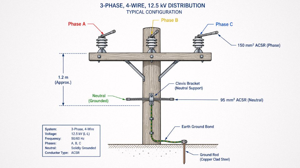
Distribution is different. Feeders operating between roughly 4 kV and 35 kV serve a mixture of three-phase industrial loads, single-phase residential drops, and commercial services that are inherently unbalanced — nobody’s neighborhood has perfectly symmetrical demand on all three phases simultaneously. Without a neutral, unbalanced return current has nowhere to go except back through the earth, which raises ground potential, introduces stray voltages on equipment frames, and can push phase-to-neutral voltages on lightly loaded phases uncomfortably high. The fourth wire solves all three problems at once.
What the Neutral Actually Does Electrically
The neutral conductor serves two simultaneous functions: it provides a low-impedance return path for unbalanced phase currents, and it anchors the system’s zero-voltage reference. That second function is less obvious but arguably more important for end-user safety. When the neutral is solid and properly grounded, customer appliances and equipment frames stay near earth potential. Lose the neutral — through a corroded connection, a broken joint, or a downed wire — and the voltage reference floats. Phase-to-neutral voltages at the service entrance can swing wildly. A 120 V appliance on a lightly loaded phase might suddenly see 180 V or more. The resulting failures are fast, expensive, and occasionally dangerous.
A broken or high-impedance neutral connection can cause overvoltage damage to customer appliances on lightly loaded phases in a split-phase or multi-wire branch circuit system.True
When the neutral is lost in an unbalanced split-phase system, the phase voltages redistribute based on load impedance ratios rather than the transformer winding ratio, causing overvoltage on the lighter load and undervoltage on the heavier load — a well-documented failure mode in utility fault investigations.
Multi-Grounded Neutral Systems and Sizing Practice
In North American distribution practice, the multi-grounded neutral (MGN) is the dominant approach. The neutral is bonded to earth at every distribution transformer and at intermediate poles spaced roughly 250–400 m apart depending on soil resistivity and utility standards. This limits touch voltages during fault conditions and gives fault current a reliable return path back to the source substation. The tradeoff is that stray current flows through the earth in parallel with the conductor — a concern in areas with buried metallic infrastructure, though manageable in practice.
Neutral conductor sizing on three-phase four-wire systems typically runs 50–100% of the phase conductor cross-section. Where the load is well-balanced and the feeder is short, utilities sometimes accept a reduced neutral — say, 70 mm² neutral on a 150 mm² phase conductor. Stretch the feeder, add more single-phase lateral taps, or feed a district with heavy residential air-conditioning load (which tends to phase-bunch), and you need a full-size neutral. Undersizing shows up as neutral overheating at connectors and measurable voltage imbalance at customers near the end of the feeder, typically in late afternoon on hot summer days.
Concentric Neutral Cables for Underground Distribution
Underground residential distribution (URD) handles the neutral differently. A concentric neutral cable wraps a set of helically applied copper wires directly around the insulated phase conductor, outside the semiconducting jacket. These wires function simultaneously as the return neutral and as an electrostatic shield, which matters for medium-voltage cable because it controls the electric field geometry and prevents localized stress concentrations that accelerate insulation aging. The copper strands are sized to carry the design neutral current, though the total cross-section is distributed across many small wires rather than one conductor — which has implications for jointing and termination practices. Get the concentric neutral connections cold-crimped rather than properly compressed and the contact resistance climbs; on a feeder that operates near thermal limit, that joint eventually fails and takes a section of cable with it.
PEN Conductors in TN-C Systems
European and Asian distribution networks frequently combine the neutral and protective earth functions into a single PEN (Protective Earth and Neutral) conductor, which is the defining feature of the TN-C earthing system. It reduces the conductor count and simplifies overhead line construction. The safety implication is real, though: if the PEN conductor is broken, equipment frames downstream lose their earth reference and can rise to a hazardous potential. Most modern practice has moved toward TN-C-S arrangements, where the combined PEN conductor is split into separate neutral and earth conductors at the service entrance, limiting the zone of exposure. The choice between these earthing philosophies is largely inherited from national standards, but procurement engineers sourcing cable for export projects need to confirm which system applies before specifying neutral conductor cross-section and insulation requirements.
Overhead Ground Wires and Shield Wires: Lightning Protection Without Carrying Load Current
Walk up to any 230 kV or higher transmission tower and look at the very top — above the phase conductors, often mounted on a short steel peak or crossarm. Those one or two wires strung at the apex are overhead ground wires (OHGW), also called static wires or earth wires depending on which utility standard you’re reading. They carry no load current under normal conditions. Their entire job is to intercept lightning before it can touch a phase conductor.
How the Shielding Angle Works
A direct lightning strike to an unshielded phase conductor injects an impulse current that the line insulation cannot tolerate — the result is a flashover, often a sustained fault, and an outage. The OHGW intercepts that strike first and routes the impulse down the tower steel and into the grounding grid at the base.
The geometry matters enormously here. The “shielding angle” is the angle formed between a vertical line through the OHGW and a line connecting the OHGW to the outermost phase conductor. IEC and IEEE design standards generally target 30–45° for conventional lines, though at higher voltages and on tall towers, designers push that angle narrower — sometimes below 20° — because a taller strike exposure zone demands tighter geometric coverage. Single-OHGW designs can work on lower-voltage lines with compact phase geometry, but on 230 kV and above, two OHGWs are effectively the industry standard. One wire positioned center-top simply cannot achieve full shielding of widely spaced phase bundles.
Materials: Galvanized Steel, Then and Now
Historically, OHGW was galvanized steel strand — EHS (extra-high strength) grade, typically 7-wire or 19-wire construction. It’s mechanically robust, accepts high tension, and handles the incidental aeolian vibration that static wires see. That’s still the dominant choice on distribution feeders and older transmission lines worldwide.
The complication is fault current. When a phase-to-ground fault occurs on the line, a portion of the return fault current flows back through the OHGW. Protective relays need somewhere between 0.1 and 0.5 seconds to clear the fault (the actual time depends on relay settings, breaker type, and system design), and during that window the OHGW must carry that current without annealing or failing mechanically. Plain EHS steel handles this adequately in most cases, but some utilities — particularly in regions with high fault-current exposure — now specify OHGW with a steel core wrapped in aluminum-clad or aluminum-alloy outer strands. The higher conductivity reduces resistive heating during fault events and also lowers power-frequency induced losses on energized segments.
Tower Footing Resistance: The Detail That Bites You Later
Here’s the piece that gets underestimated during design and causes expensive retrofits later. The OHGW only does its job properly if the impulse current actually dissipates into the ground quickly. If tower footing resistance is too high, the voltage at the tower top rises sharply during a strike — sometimes fast enough to cause a back-flashover, where the overvoltage jumps from the tower steel back to the phase conductor through the air gap. That’s the failure mode the OHGW was supposed to prevent.
IEC 60071 and IEEE Std 1243 recommend tower footing resistance below 10 ohms, with below 5 ohms preferred on high-exposure lines, to prevent back-flashover during lightning events.True
Both standards address insulation coordination and lightning performance, and the sub-10-ohm target for footing resistance is well-established in transmission line design practice. Rocky terrain and dry soils frequently push actual values well above this, requiring driven rods, counterpoise cables, or chemical grounding enhancement.
Rocky terrain and dry climates are the chronic offenders. A footing resistance of 25–40 ohms — not unusual in high-altitude or granite-heavy terrain — can negate much of the OHGW’s protection value even with perfect shielding geometry. Counterpoise cables buried radially from the tower base, or driven ground rods with conductive backfill, are the usual remedies. It’s tedious, adds cost per tower, and gets skipped when project budgets are tight. Then the line underperforms on lightning outage rates and nobody immediately connects the cause.
The Outage Rate Case for Keeping Them
The economic argument for OHGWs occasionally gets questioned during project value-engineering. The hardware — tension clamps, vibration dampers, dead-end assemblies, the additional tower loading — is real cost. On a 200-kilometer 345 kV line, that adds up.
But the outage performance data is clear enough to end that conversation quickly. Lines equipped with properly designed OHGWs typically experience 70–90% fewer lightning-caused outages than comparable unshielded lines. The range depends on local keraunic level (thunderstorm-days per year), terrain, footing resistance quality, and shielding angle achieved. In high-lightning-density corridors — parts of Southeast Asia, Central Africa, equatorial South America — unshielded transmission lines would face outage frequencies that no grid operator could accept commercially.
Segmented and Insulated OHGWs
One operational nuance worth flagging before the next section: on long lines, a fully grounded OHGW running the entire length acts as a shorted turn around the magnetic field of the energized phase conductors, inducing a circulating power-frequency current. On very long lines, those induced losses aren’t trivial — they represent real energy waste and add heat cycling to the wire.
The workaround is to section the OHGW electrically — insulators are inserted at certain towers, breaking the continuous conductor into segments while small spark gaps or surge arresters restore the ground connection for lightning purposes. The lightning protection function is preserved; the circulating current path is broken. It’s a reasonable engineering compromise, and it also opens the door to the most commercially significant evolution of the static wire concept: the OPGW, or optical ground wire, which carries fiber-optic telecommunications inside a conductor that also performs the OHGW function — covered in the next section.
OPGW and ADSS: Fiber-Optic Cables Hidden Inside and Alongside Power Lines
Not every wire on a transmission tower is there to move electrons. Two of the most technically interesting cables in modern grid infrastructure carry zero load current — yet utilities are spending heavily to install or retrofit them on lines across every continent. OPGW and ADSS are how the grid talks to itself.
OPGW: When Your Ground Wire Is Also a Fiber Highway
Optical Ground Wire replaces the conventional overhead ground wire entirely. Same tower attachment point, same mechanical tension role, same lightning shielding function — but inside the armor strands, there’s a fiber-optic tube carrying anywhere from 12 to 144 individual glass fibers. Those fibers handle SCADA telemetry, protection relay signaling, voice circuits for operations staff, and increasingly the real-time data flows that smart grid applications demand. A single OPGW span can carry more communication bandwidth than a utility’s entire legacy microwave radio network.
Construction starts at the center and works outward. The optical unit — a stainless steel or sometimes aluminum tube housing the fiber bundle in a gel-filled or dry-buffered arrangement — sits at the core. Around that tube, alternating layers of aluminum-clad steel (ACS) wires or aluminum alloy wires provide the tensile strength and, critically, the short-circuit current rating. That rating is expressed in kA²·s, which tells you how much fault energy the conductor can absorb without the core temperature spiking high enough to damage the fibers. Specify this wrong and a nearby phase fault can cook a run of fiber you cannot easily replace. Typical project specifications run from around 50 kA²·s on lower-voltage lines up to 150–200 kA²·s on 500 kV and above, depending on fault clearing time and system impedance at that point in the network.
Because OPGW is metallic, it must be bonded and grounded at every tower — which is fine on a new-build or on a line that’s being refurbished anyway. Where it gets complicated is retrofitting a distribution circuit that’s been energized for thirty years with marginal tower structures. Re-tensioning the ground wire position disturbs everything.
ADSS: Fiber With No Metal, No Grounding Headache
All-Dielectric Self-Supporting cable was developed specifically for that retrofit scenario. There are no metallic elements at all — the tensile load is carried by aramid yarn (Kevlar-type) strength members embedded in the cable jacket, and the whole assembly hangs on its own without a separate messenger wire. You can attach ADSS to an existing pole or tower at a mid-span attachment point without re-engineering the ground wire terminations.
The catch — and it’s a real one that gets overlooked by procurement teams who aren’t deep in HV engineering — is electric field placement. On a live distribution line, the space between conductors isn’t electrically neutral. Induced voltage on a dielectric cable jacket, if it exceeds the cable’s tracking resistance threshold, causes dry-band arcing that slowly erodes the sheath over years. The fix is to install ADSS in the “neutral zone” of the electric field gradient, typically calculated per the specific tower geometry and voltage level of the circuit. Get the attachment height wrong by a meter or two and you’re looking at premature sheath failure — usually discovered when the fiber attenuation starts climbing and someone eventually cuts into the cable to find carbonized tracking damage.
ADSS is the right answer when induced voltage on metallic conductors would be problematic, when tower structures won’t support re-tensioning, or when a utility needs to add fiber to an existing distribution network quickly without taking outages to rework ground wire hardware.
ADSS cable contains no metallic conductors and can be safely installed on energized power lines without grounding requirements.True
ADSS (All-Dielectric Self-Supporting) cable is constructed entirely from non-metallic materials — optical fibers, aramid strength members, and polymer jackets — which means it carries no induced current and requires no electrical bonding or grounding at attachment points, a key installation advantage over OPGW on retrofit projects.
OPGW vs. ADSS: Choosing the Right Cable for the Application
| Factor | OPGW | ADSS |
|---|---|---|
| New transmission line build | First choice | Rarely used |
| Retrofit on existing distribution line | Requires tower re-work | Preferred |
| Voltage level | All transmission, HV distribution | Typically ≤110 kV |
| Lightning shielding function | Yes — replaces ground wire | No |
| Short-circuit rating required | Yes (kA²·s specified) | Not applicable |
| Electric field placement critical | No | Yes — must verify |
| Metallic bonding at towers | Required | None |
Market Direction and What It Means for Procurement
The global OPGW market sat at roughly USD 2.1 billion in 2023, and most analyst projections have it growing at 7–9% annually through the end of the decade. The drivers are straightforward: smart grid rollouts in Southeast Asia and the Middle East, grid hardening programs in North America after storm-related outages, and renewable integration projects that need reliable protection relay communication between substations that didn’t previously talk to each other. Procurement lead times on OPGW have tightened — especially for higher fiber counts and elevated short-circuit ratings — so building buffer time into project schedules matters more than it did five years ago.
Jinda produces OPGW across short-circuit ratings from 50 kA²·s to 200 kA²·s and fiber counts from 12 to 144, manufactured to IEC 60794-4-10 and IEEE 1138. Supply has gone to overhead line projects in Southeast Asia and the Middle East, and the engineering team can work through kA²·s calculations and tower load compatibility on a project-specific basis — useful when you’re trying to match a replacement OPGW to an existing tower’s conductor attachment hardware without a full structural re-analysis.
How to Identify Each Wire Type by Position, Color Code, and Physical Appearance
Knowing what each wire does is only half the job. The other half is being able to look at a tower or pole in the field — or review a line photograph during procurement review — and confirm you’re actually looking at what you think you’re looking at. Position is your first, fastest clue.
Position as the Primary Identifier
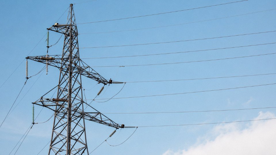
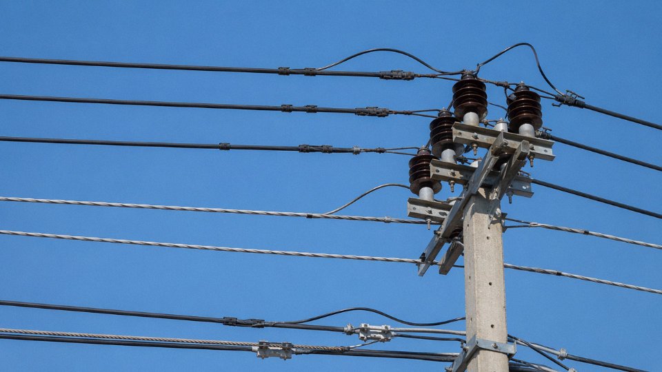
On a standard lattice transmission tower, the arrangement is almost always the same: overhead ground wires (OHGWs) or OPGW sit at the very top, either on the peak of the tower or on short arms above the main crossarms. They are there specifically to intercept lightning before it reaches the phase conductors below. The three phase conductors occupy the middle zone — arranged in a flat horizontal configuration on most double-circuit and EHV towers, or in a delta or vertical arrangement on older or more compact structures. On distribution poles (your typical wood pole street-side installation), the neutral runs below the phase conductors, often a noticeably smaller wire strung with less tension, sometimes sharing the pole with secondary service drops.
If you see a wire mounted lower than everything else on a wood pole, running more loosely than the phase conductors, it is almost certainly the neutral. On transmission lattice towers, there is no neutral — the three-wire system up there carries no return path along the line itself.
Surface Appearance and Diameter
Visual texture tells you a surprising amount, once you know what to look for.
ACSR phase conductors have a bright aluminum-silver surface with a clearly visible helical strand pattern — the outer wires wrap in a gentle helix you can see from the ground with reasonable lighting. Diameter varies widely depending on conductor rating, but a typical 477 kcmil “Hawk” ACSR is roughly 21 mm across, which is visually substantial.
Galvanized steel OHGW is duller. It has a gray-silver tone rather than the clean brightness of aluminum, and it runs at a noticeably smaller diameter than the phase conductors it protects — often 10–14 mm on lines where the phase conductors are 20+ mm. The zinc coating weathers to a flat gray fairly quickly, so an older line’s OHGW often looks distinctly different in color from the phase conductors even on a casual inspection.
OPGW is the tricky one. It is designed to look structurally similar to a small ACSR or steel ground wire, and at a distance it often does. The giveaway is diameter: OPGW is engineered to a specific tensile requirement, and for its strength class it tends to run slightly smaller in diameter than a purely steel wire of equivalent breaking load, partly because aluminum-clad steel strands are used in the outer layers. In good light you may also notice a marginally shinier surface compared to a plain galvanized wire.
Phase Identification Markers
Color coding on phase conductors is not universal, which creates real confusion on international projects. Under IEC conventions, the common sequence is brown/black/grey (newer IEC 60446 standard) or red/yellow/blue in older installations — the specific colors depend on the country, the utility, and the age of the line. North American practice often uses black for A-phase, red for B-phase, and blue for C-phase, though this varies by utility. Some conductors carry a colored tracer strand woven into the outer layer; others use spiral marking tape applied at intervals during installation.
Phase conductor color codes are standardized globallyFalse
Color coding conventions differ between IEC and North American standards, and vary further by country, utility, and installation era. Never assume a specific color means a specific phase without confirming the applicable local standard.
On bare aluminum conductors running at distribution voltages, the color tape weathers badly and can be nearly unreadable on a line that’s been up for 15 or 20 years. In practice, position and hardware type are more reliable identifiers than color on aged infrastructure.
Corona Rings and Suspension Hardware
At 345 kV and above, phase conductors typically show aluminum corona rings — toroidal rings fitted around suspension clamp assemblies and at dead-end hardware. Their function is to smooth the electric field gradient and prevent localized corona discharge that would otherwise cause radio interference and accelerate hardware degradation. They’re a reliable visual indicator that you’re looking at a phase conductor, not a ground wire. OHGW hardware has no corona rings, because the wire sits at ground potential and the field stress simply isn’t there.
Arcing horns — the horn-shaped electrodes fitted to insulators on some distribution and subtransmission lines — also appear only on energized conductors. No horn, no insulator stack: you’re probably looking at a grounded wire.
Bundled Conductors as a Voltage Indicator
Bundled conductors are one of the clearest immediate identifiers in the field. When you see spacer-damper frames holding two, three, or four parallel conductors at regular intervals — typically every 50–80 m of span, give or take depending on conductor type and wind zone — you are looking at a high-voltage transmission line, almost certainly 230 kV or above. Twin-bundle is common from roughly 230 kV up; quad-bundle appears on 500 kV and 765 kV lines where current carrying capacity and corona control demand it. Distribution lines simply don’t use bundles. A single conductor per phase position means either a distribution line or a lower-voltage subtransmission circuit.
A Necessary Safety Note
All of this identification logic is for planning, procurement review, line inspection, and educational purposes. Every overhead conductor must be treated as fully energized regardless of what it looks like or where it sits on the tower. Minimum approach distances under OSHA 1910.269 and IEC 60900 are non-negotiable, and “it looked like the ground wire” is not a defense against arc flash. Qualified line workers follow strict energized-line protocols; everyone else stays clear.
Voltage Class vs. Wire Configuration: How Transmission and Distribution Lines Differ in Wire Count and Arrangement
Walk past a neighborhood utility pole and count the wires. Then stand under a 500 kV lattice tower and look up. The difference isn’t just voltage — it’s an entirely different engineering philosophy expressed in steel, aluminum, and geometry. Understanding those differences is practical knowledge for any engineer specifying conductors or a procurement team building a BOM for a grid project.
Low-Voltage Secondary Lines (120/240 V Single-Phase, 400 V Three-Phase)
At the bottom of the voltage ladder, secondary distribution lines typically run 2 to 4 wires on wooden poles at heights of 4–8 m. In North America, the classic single-phase service drop is two insulated conductors plus a bare neutral messenger, twisted together — a configuration so familiar it barely registers as engineered. In Europe, Brazil, and increasingly across Southeast Asia, aerial bundled conductor (ABC cable) has become the standard approach: all conductors, including neutral, twisted into a compact self-supporting bundle. ABC eliminates most phase-to-neutral faults caused by contact with tree branches, reduces electrocution risk to linesmen and the public, and cuts technical losses on long rural laterals. The trade-off is slightly higher upfront conductor cost, which typically pays back within a few years on lines with meaningful fault history.
Medium-Voltage Distribution (4 kV to 35 kV)
This is where the majority of distribution infrastructure lives. A standard three-phase four-wire MV line — common at 12.47 kV, 22 kV, and 33 kV — carries three phase conductors and one neutral, usually ACSR ranging from roughly 50 mm² to 240 mm² depending on load density and span length. Phase-to-phase spacing runs 0.9 m to 2.0 m, governed by the system voltage and the applicable national standard (IEC 60038 jurisdictions space things differently than ANSI systems). In practice, a lot of older 11 kV lines in Asia are running conductor cross-sections that made sense thirty years ago but are now thermally constrained due to load growth — reconductoring with higher-capacity ACSR or ACCC is increasingly common on these circuits.
Sub-Transmission Lines (66 kV to 138 kV)
At this tier, the neutral disappears. Three-phase three-wire configurations dominate. Towers are steel or concrete, ACSR conductor cross-sections typically fall between 150 mm² and 400 mm², and one or two overhead ground wires sit at the tower peaks. Some 69 kV and 115 kV lines run as single-circuit; others share a tower with a second circuit, which starts to noticeably increase the wire count visible on any given structure.
EHV Transmission (230 kV to 500 kV)
Here the configurations get visually striking. At 500 kV, thermal and corona requirements make a single large conductor per phase impractical, so each phase position uses a bundle — twin, triple, or quad subconductors held apart by spacers at regular intervals along the span. A single-circuit 500 kV tower with quad-bundle phases and two OHGW at the peak carries 14 wires total (12 subconductors plus 2 ground wires), none of them a neutral. Double-circuit towers on the same structure can carry 26 or more visible wires, depending on bundling configuration. Phase arrangement on double-circuit towers is often optimized for low reactance (opposite-phase circuits interleaved vertically) to reduce mutual inductance between circuits.
UHV Transmission (750 kV and Above)
Bundle counts increase further — six or even eight subconductors per phase at 1,000 kV UHV AC lines is not unusual in China’s grid expansion program. Tower heights frequently exceed 50 m, and conductor cross-sections in the 400–630 mm² range are common per subconductor. OPGW almost universally replaces conventional OHGW at this voltage class, combining lightning protection with fiber-optic communications in a single ground wire position.
Reference Configuration Table
| Voltage Class | Typical System | Phase Conductors / Circuit | Neutral Present | OHGW Count | Common Conductor Type | Typical Cross-Section (mm²) |
|---|---|---|---|---|---|---|
| LV Secondary (≤1 kV) | 1-phase or 3-phase | 2–3 | Yes | None | ABC or insulated XLPE | 16–120 |
| MV Distribution (4–35 kV) | 3-phase 4-wire | 3 + neutral | Yes | 0–1 | ACSR, AAAC | 50–240 |
| HV Sub-transmission (66–138 kV) | 3-phase 3-wire | 3 | No | 1–2 | ACSR | 150–400 |
| EHV Transmission (230–500 kV) | 3-phase 3-wire | 3 (twin–quad bundle) | No | 2 | ACSR, ACCC | 300–630 per sub |
| UHV Transmission (750 kV+) | 3-phase 3-wire | 3 (quad–octet bundle) | No | 2 (OPGW) | ACSR, ACCC | 400–630 per sub |
The bundling geometry and tower configuration you specify upstream — during early project engineering — locks in conductor type and cross-section choices that procurement can’t easily reverse later. Getting the voltage class and configuration right at the specification stage is worth considerably more than squeezing unit price on the conductor itself.
A standard 500 kV single-circuit transmission tower with quad-bundle phase conductors and two overhead ground wires carries 14 total wires, with no neutral conductor present.True
500 kV EHV transmission uses three-phase three-wire configuration with no neutral. Quad-bundle means four subconductors per phase position, giving 12 phase subconductors total. Two OHGW or OPGW at tower peaks bring the visible wire count to 14 on a single-circuit structure.
Conductor Material Selection Criteria: Aluminum, Copper, Steel, and Composite Core Compared
The choice of conductor material is not a catalog decision — it drives tower spacing, foundation loads, sag clearance, maintenance intervals, and whole-life cost. Get it wrong and you are either over-building structure for no reason or watching conductors creep into minimum ground clearance after five hot summers.
Why Aluminum Displaced Copper on Overhead Lines
Aluminum conducts at roughly 61% of copper’s conductivity by cross-section, which sounds like a disadvantage until you look at density. Aluminum is about 30% as heavy as copper per unit volume. Run the numbers for a fixed weight-per-unit-length budget — which is what determines sag and tower loading — and aluminum wins decisively for long spans. You end up with a larger-diameter conductor that actually helps corona performance at high voltage, and towers spaced farther apart.
For the same weight per unit length, an aluminum conductor carries more current than a copper conductor of equivalent weight.True
Aluminum's conductivity-to-density ratio (approximately 61% IACS conductivity at ~30% of copper's density) means that weight-equivalent aluminum conductors have greater cross-sectional area and higher ampacity than copper conductors of the same linear mass, making aluminum economically dominant for overhead applications.
The shift happened gradually through the mid-twentieth century as transmission voltages climbed and span lengths grew. By the time utilities were stringing 345 kV and 500 kV lines across hundreds of kilometers, copper was simply not viable at the required sag limits without absurd tower heights.
Where Copper Still Belongs
That said, copper does not disappear. It dominates substation buswork, grounding conductors, transformer windings, and underground medium-voltage cables — anywhere compactness and connection reliability matter more than weight budget. A compact busbar running 20 meters inside a substation does not care about sag. An underground cable has the soil to support it.
One counterintuitive issue in some markets: copper’s scrap value makes it a theft target. Distribution lines in certain regions have switched to aluminum partly because stripping aluminum conductor is less economically attractive to thieves. Ironic, but real.
What the Steel Core Actually Does in ACSR
ACSR — aluminum conductor, steel reinforced — is the workhorse of global transmission, accounting for somewhere between 50–60% of installed overhead conductor worldwide, depending on the region. The concept is a clean mechanical division of labor: the aluminum strands handle the electrical current, the steel core carries the mechanical tension.
The Drake ACSR conductor, a common reference in North American and international specifications, has a rated breaking load around 140 kN. That tensile capacity is what allows spans of 400–600 m across valleys, rivers, or mountain crossings while staying within sag limits under ice and wind loading. Without the steel core, the aluminum alone would creep and sag under sustained tension at elevated temperature.
Aluminum Alloy Conductors and the Corrosion Problem
Pure 1350-H19 aluminum is excellent electrically but relatively soft and susceptible to deep corrosion when a steel core is present in aggressive environments. Galvanic interaction between the aluminum strands and the steel core — accelerated by coastal salt fog, industrial sulfur dioxide, or tropical humidity — can hollow out ACSR conductors from the inside over 20–30 years without obvious surface damage.
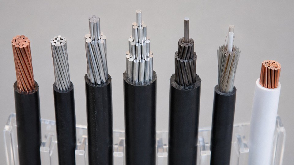
AAAC (all-aluminum alloy conductor) using 6201-T81 alloy addresses this directly by eliminating the steel core entirely. The alloy achieves around 52.5% IACS conductivity while reaching significantly higher tensile strength than pure 1350 aluminum, enough to meet the mechanical demands of most distribution and sub-transmission spans. For coastal industrial projects or tropical grid builds, specifying AAAC instead of ACSR is not over-engineering — it is avoiding a corrosion-driven reconductoring project in year 25.
Composite Core: The High-Temperature Play
Carbon-fiber and glass-fiber composite core conductors — ACCC and ACSS/TW being the most widely deployed types — change the thermal operating envelope substantially. A steel core expands significantly with temperature, which is precisely why conventional ACSR sag increases as load and ambient temperature rise. Composite cores have a coefficient of thermal expansion roughly 4–5 times lower than steel.
The practical result: composite-core conductors can operate continuously at 180–200°C with sag roughly equivalent to ACSR running at 75°C. On a congested corridor where building new towers is politically or economically blocked, that thermal headroom can effectively double the power transfer capacity on existing rights-of-way. The conductor costs more per kilometer — sometimes substantially more — but that cost is weighed against tower construction, land acquisition, and permitting, which easily run into millions per kilometer in developed markets.
Environment-Specific Selection
Arctic installations require conductors that stay ductile at -50°C without brittle fracture during stringing or ice-shedding events. Desert lines face UV degradation of any polymer components and abrasive sand working into strand interstices. Coastal salt-fog zones demand either AAAC or ACSR with grease-filled cores and boron-inhibited compound packed between layers — something worth confirming with the manufacturer’s stranding specification rather than assuming it is standard.
Jinda’s product range covers ACSR, AAAC, ACAR, OPGW, and composite-core variants, with production processes calibrated for IEC 61089 and ASTM B232 standards depending on the destination market. For projects where the environment is genuinely mixed — say, a line that runs from a coastal substation inland through industrial zones — it is worth working through the conductor selection with someone who has seen what those environments do to installations over a 30-year asset life.
Frequently Asked Questions About Power Line Wires
Why do some power lines have 3 wires while others have 7 or more?
Wire count reflects three overlapping variables: voltage class, circuit count, and whether neutral and ground wires are present. A single-circuit 3-phase transmission line in its simplest form has three phase conductors plus one or two overhead ground wires — so five wires total, though at a glance people count three “main” ones and overlook the top wires entirely. Add a second circuit on the same tower and you’re at six phase conductors. Bring it down to distribution voltage, add a neutral, and install two OHGWs, and you’re looking at eight conductors on one structure. Double-circuit distribution lines with a shared neutral or a separately run communication messenger can push that to nine or ten. The short answer: three usually means a bare transmission circuit; seven or more almost always means double-circuit, neutral-present, or a communication cable has been strung alongside.
Are the top wires on a transmission tower energized?
No. The topmost wires are overhead ground wires — either bare galvanized steel, ACSR, or OPGW — and they are bonded to the tower steel and grounded at every structure. Under normal operation they carry essentially zero current. What they can carry, briefly, is a very high fault or lightning impulse current: a direct lightning strike to a phase conductor that gets intercepted by an OHGW may divert tens of kiloamperes to ground in microseconds. That’s not “energized” in any useful operational sense, but it’s a real reason you don’t handle them as dead wire without confirming with a clamp-on ammeter and proper lockout procedures.
Overhead ground wires on transmission towers carry no normal operating voltage.True
OHGWs are intentionally grounded at every tower and operate at ground potential under steady-state conditions; they only conduct during fault or lightning events.
Why are power line conductors not insulated like household wiring?
At 500 kV, a solid XLPE insulation layer capable of withstanding full line-to-ground voltage would need to be roughly 25–40 mm thick around the conductor — and that’s before accounting for the mechanical reinforcement needed to stop it from cracking under sag and thermal cycling over a 50-year service life. The resulting cable would weigh several kilograms per meter, which is economically and structurally unworkable for spans of 300–500 m. Overhead lines use air as the dielectric. Clearance distances — from conductor to tower steel, conductor to ground, conductor to conductor — are engineered to prevent flashover at the design voltage. It’s a practical trade-off that’s been proven for over a century, not a shortcut.
What causes power lines to vibrate and hum?
Two separate phenomena, often confused. The mechanical vibration — visible as a fine, high-frequency oscillation of the conductor — is aeolian vibration, driven by wind creating alternating vortex shedding on the leeward side of the conductor. Frequency typically falls between 3 and 150 Hz depending on conductor diameter and wind speed. Stockbridge dampers, those small dumbbell-shaped weights clamped near suspension points, are specifically tuned to absorb this energy before it accumulates into strand fatigue failures. The audible hum near substations and large transformers is a different matter entirely: 100 Hz or 120 Hz noise (double the power frequency) from magnetostriction in transformer cores, plus some corona discharge from conductors in high-humidity conditions. The two are unrelated mechanically, though both get reported as “the line is humming.”
Can I tell the voltage of a power line just by looking at it?
Not with precision, but experienced linemen and engineers do it routinely as a rough sanity check. Insulator string length is the most useful indicator: each standard cap-and-pin disc insulator provides roughly 15–20 kV of dry flashover protection, so a string of 20 discs suggests somewhere in the 230–345 kV range. Conductor bundling is another signal — two conductors per phase points toward 230 kV and above; four-conductor bundles appear on 500 kV and higher. Tower height and crossarm geometry also matter, though tower designs vary enough by region and utility that they’re less reliable as voltage indicators than insulator count.
What is the difference between a power line conductor and a power cable?
A conductor, in the overhead line sense, is an uninsulated or very lightly surface-treated wire that depends entirely on air gap for dielectric isolation. A cable is a fully insulated assembly — XLPE or EPR insulation rated for the full line-to-ground voltage, with a metallic screen, bedding, and outer sheath — designed for underground or submarine installation where air insulation is unavailable. The engineering trade-offs are substantial: cables cost three to ten times more per kilometer than equivalent overhead conductors for the same voltage class, but they eliminate right-of-way issues and visual impact. Jinda manufactures both product families, which in practice means the conductor selection conversation and the cable selection conversation involve very different parameters even when the project voltage is identical.
How long do overhead conductors last, and what causes replacement?
ACSR and similar aluminum conductors are typically designed for 40–60 years of service life, though actual service life varies considerably with loading history and environment. Replacement is usually triggered by one of four conditions: annealing of the outer aluminum strands from sustained operation above roughly 75–85°C (which permanently reduces tensile strength and increases sag), corrosion of the galvanized steel core visible as rust streaking at the strand interstices, a confirmed reduction in rated breaking strength below an acceptable threshold on tensile testing, or a deliberate reconductoring project to increase line ampacity — often by replacing standard ACSR with high-temperature low-sag conductors like ACCC or TACSR that can operate at 150°C and above without violating clearance limits. In practice, the reconductoring case is increasingly common as utilities try to extract more capacity from existing transmission corridors without building new towers.
Selecting the Right Conductor for Your Project: A Practical Procurement Checklist
Getting the technical specification right before you issue a purchase order saves far more money than negotiating price after the fact. A conductor undersized for fault current, or specified without accounting for coastal salt spray, will cost you — in derating, in accelerated corrosion, in re-tensioning after unexpected sag. The checklist below is what a competent project engineer should confirm before sending an RFQ to any conductor manufacturer.
The 10-Point Specification Checklist
1. System voltage class. Start here. Whether you’re at 11 kV distribution or 500 kV transmission determines conductor bundle configuration, minimum clearances, and corona performance requirements. Don’t just write “high voltage” — specify the rated voltage, the highest system voltage, and whether the line is single- or double-circuit.
2. Ampacity at defined conditions. State the continuous current rating and the ambient temperature and maximum conductor temperature you’re designing to. A conductor rated at 800 A in a 25 °C temperate climate may derate to 650–700 A in a 45 °C desert environment — that gap has derailed more than a few projects.
3. Mechanical tension and sag limits. Specify your ruling span, maximum design ice load (if applicable), design wind pressure, and the maximum allowable sag at the conductor’s highest operating temperature. These numbers drive stringing tension and directly affect tower loading. Get this wrong and you’re either rebuilding towers or accepting clearance violations.
4. Environmental exposure class. Standard inland, coastal (salt-laden atmosphere), tropical high-humidity, arctic (−40 °C installation), or industrial (H₂S or chemical exposure). Each calls for different surface treatment or alloy selection — heavy-draw grease filling, zinc-5% aluminum alloy coating, or anodizing, depending on the standard you’re working to.
5. Conductor type and applicable standard. ACSR to IEC 61089 or ASTM B232, AAC to IEC 61089, ACCC, HTLS variants — name it explicitly. Different markets have different testing regimes, and a conductor shipped to an Australian utility under AS/NZS 1531 requires different documentation than the same physical product shipped to a European TSO under EN 50182.
6. OHGW or OPGW requirement with short-circuit rating. If you need a ground wire, specify the fault-current withstand as a thermal duty in kA²·s. Undersized OHGW has burned off during fault events. State this number; don’t leave it implicit.
7. Fiber count if OPGW is required. 24-fiber and 48-fiber are the most common in utility backbone applications, but some projects need 96 or more for substation automation and protection relay channels. Fiber count, tube count, and attenuation spec all affect the optical unit design and the overall cable diameter — which in turn affects the aerodynamic load.
8. Installation method. Standard ground stringing, helicopter installation for river crossings or mountain terrain, or pulling through existing dead-end structures all require different reel sizes, drum weights, and conductor surface finish specifications.
9. Termination and jointing hardware compatibility. Confirm whether you’re using compression or bolted-type fittings, and which manufacturer’s hardware series. A mismatch between conductor stranding geometry and compression die profile is a surprisingly common cause of joint failures in service.
10. Delivery timeline and packaging. This is often left until last and then causes the most pain. State your required ex-works or FOB date, the port of destination, and whether you need wooden reels (standard sea freight) or steel reels (long storage, rough handling). Reel diameter affects container loading — worth checking before the order is placed.
Total Cost of Ownership: The Calculation Most Buyers Skip
The conductor’s purchase price is typically 15–30% of total line project cost, depending on terrain and tower type. Over a 40-year asset life, resistive losses in the conductor frequently exceed the original purchase price several times over. A higher-conductivity ACCC or ACSR/AW conductor may cost 20–35% more per meter than standard ACSR, but reduced I²R losses — which Jinda estimates at roughly 0.05–0.12 USD per kWh of line losses avoided, depending on local electricity pricing and load factor — can recover that premium within 5–12 years on a loaded transmission circuit.
Upgrading from standard ACSR to a high-temperature low-sag (HTLS) conductor on an existing line can increase thermal capacity by 50–100% without requiring new tower structures, depending on existing sag margins.True
HTLS conductors such as ACCC and TACSR exhibit significantly lower thermal elongation than conventional ACSR, allowing operation at higher temperatures within existing clearance envelopes. The actual capacity gain depends on the original design sag margin, span lengths, and ambient conditions — a qualified line rating study is required to confirm the achievable uprate for any specific circuit.
Tower upgrades are expensive and slow. If an existing corridor can be uprated with a conductor swap, the TCO math often favors the premium conductor decisively. Run the numbers before defaulting to the cheapest ACSR quote.
Jinda’s Project Support Process
Jinda’s technical team offers conductor selection simulation as part of pre-order support — no charge, no obligation. Send span data, load profile, and ambient conditions; the team returns a conductor comparison including sag-tension outputs and loss calculations. Samples can be provided for qualification testing before commitment to a full production order.
Every shipment comes with a full documentation package: factory test certificates, material test reports (MTRs) covering chemical composition and mechanical properties for each production lot, and country-of-origin certification for customs clearance. Inspection and Test Plans (ITPs) can be aligned to customer-nominated hold and witness points, or to a third-party inspection agency of the buyer’s choice — SGS, Bureau Veritas, TÜV, and others have standing relationships with Jinda’s five production facilities.
Logistics and Lead Times
Standard ACSR and AAC: 4–8 weeks ex-works, depending on cross-section and quantity. OPGW and specialty high-temperature conductors: 8–14 weeks. Urgent partial quantities — say, a replacement drum for a damaged section mid-project — can often be fulfilled from finished-goods inventory within days. It’s worth asking; Jinda maintains stock of common sizes precisely because project emergencies don’t respect production schedules.
Jinda holds ISO 9001 quality management and ISO 14001 environmental management certifications. Products are tested to IEC, ASTM, AS/NZS, and BS standards depending on the destination market, which means test reports can be inserted directly into tender documentation without additional third-party qualification steps in most jurisdictions.
To get a technical proposal, contact Jinda’s international sales team with your project specification — even a preliminary one. Engineering support is provided at no charge as part of the long-term supply partnership model. The conversation is worth starting early; conductor specifications locked in at the design stage are far cheaper to get right than changes after tower foundations are poured.