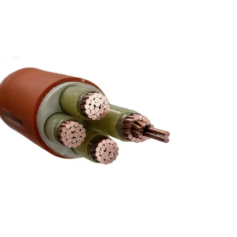
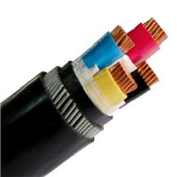
Running network cable and power conductors through the same conduit feels like a reasonable shortcut — fewer holes in the wall, one pull instead of two, faster rough-in. On a busy construction site or during a plant retrofit, that logic is hard to argue with. The problem shows up later: intermittent packet loss, a switch port that renegotiates down to 100 Mbps for no obvious reason, a SCADA link that drops exactly when a large motor starts. Chasing that kind of fault is expensive. A maintenance tech burning two days hunting a ghost in a network that was wired wrong from day one will cost more than the conduit savings ever justified.
You can run Cat6 in the same conduit as 120V power under specific conditions, but the NEC does not make it easy. Article 800.133(A)(1)(b) requires at least 50 mm (2 inches) of separation between communications and power conductors inside a shared raceway unless a permanent barrier is installed. In practice, most installers avoid it entirely — not because it’s always illegal, but because the induced noise from a 120V/60Hz circuit can push 5–15 mV onto unshielded Cat6, which is enough to erode the SNR margin that Gigabit Ethernet depends on.
What makes this genuinely tricky is that the rules and the physics are two separate problems, and satisfying one doesn’t automatically satisfy the other. A run that’s code-compliant on paper can still perform badly, and a run that tests clean at installation can degrade after load conditions change or additional circuits get pulled into the same conduit months later. The answer depends on cable type, conduit fill, circuit loading, and how much network reliability the application actually demands.
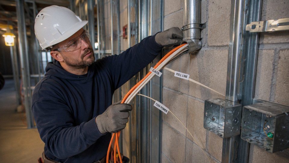
What the NEC, TIA-568, and Local Codes Actually Say About Shared Conduit Routing
The short version: the codes don’t give you a clean yes or no. What they give you is a set of conditions, and whether your installation is legal depends on which conditions you can actually satisfy on that specific run, in that specific building, with that specific inspector.
NEC Article 800.133(A)(1)(b) — The 50 mm Separation Rule
This is the clause most installers know, or half-know. It requires that communications cables — Cat6 included — maintain a minimum 50 mm (2 inches) of separation from Class 1, 2, and 3 power circuits when both occupy the same raceway without a fixed barrier between them. Class 1 circuits cover most 120 V branch circuit wiring you’d encounter in a commercial or light industrial setting, so this applies directly to the scenario.
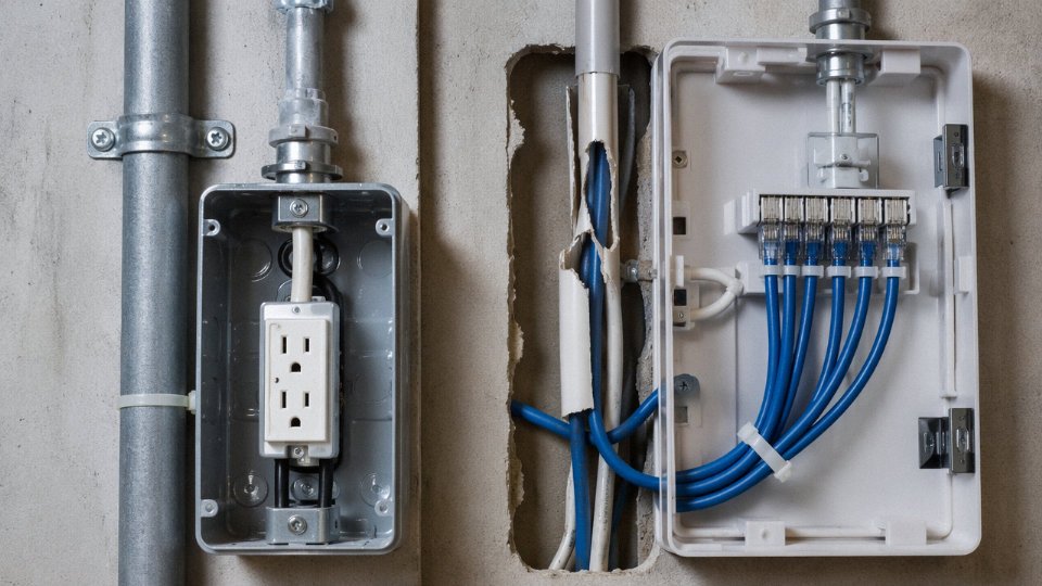
The barrier exception is real but narrow. If a listed divider or continuous partition physically separates the conductors inside the conduit or wireway, you can reduce that gap — but the barrier has to be rated and installed per the listing, not improvised with split loom or tape. In practice, conduit systems rarely accommodate true internal barriers. Rectangular wireways and cable trays are where that exception gets used.
NEC Article 800.133(A)(1)(b) requires a minimum 50 mm separation between communications cables and power conductors in shared raceways unless a listed barrier is installed.True
This requirement appears in the 2023 NEC Article 800.133(A)(1)(b) and has been consistent across recent code cycles. The 50 mm figure is a minimum, not a recommended value.
NEC Article 800.133(A)(2) — Listed Communications Raceways
This subsection opens a second path. Under specific conditions, power and communications cables may share an enclosure if the raceway is listed as a communications raceway and the power conductors are limited to those supplying communications equipment directly — not general branch circuits. That distinction matters enormously. A listed communications raceway running power to a PoE switch is a different scenario than pulling a 120 V receptacle feed alongside your Cat6 backbone. Most general-purpose EMT or PVC conduit is not listed as a communications raceway, so this exception doesn’t apply just because the conduit is plastic.
TIA-568.2-D — The Structured Cabling Perspective
TIA-568.2-D approaches this from a signal integrity angle rather than a safety angle, which means it often sets stricter practical limits than the NEC minimum. The standard calls for 50 mm separation between Cat6 UTP and power cables running parallel, and increases that to 100 mm when the cables cross at angles less than 90 degrees. A perpendicular crossing — true 90 degrees — is considered low risk and requires no enforced gap. Oblique crossings in a congested ceiling plenum are where people routinely violate this without realizing it.
OSHA 29 CFR 1910.303
In commercial and industrial settings, OSHA enters the picture through 1910.303, which governs electrical installations and references NEC compliance as the baseline standard. For plant-floor work specifically, where Cat6 might run alongside 120 V machine control circuits in the same cable tray, an OSHA citation can follow a failed inspection even if the NEC violation seems minor. The exposure isn’t theoretical — it shows up in routine safety audits.
AHJ Interpretation: The Variable Nobody Talks About Enough
The Authority Having Jurisdiction can and routinely does impose requirements stricter than the NEC baseline. Some jurisdictions require complete physical separation — separate conduits, full stop — regardless of what 800.133 permits. Before you commit a conduit layout to concrete or fasten it to structure, get a written pre-inspection ruling. A five-minute conversation with the local electrical inspector saves a complete re-pull later.
| Code / Standard | Clause | Minimum Separation | Conduit Type Allowed | Key Exception |
|---|---|---|---|---|
| NEC 2023 | 800.133(A)(1)(b) | 50 mm (2 in.) | Any listed raceway | Listed barrier eliminates gap requirement |
| NEC 2023 | 800.133(A)(2) | None specified | Listed communications raceway only | Power must supply comms equipment only |
| TIA-568.2-D | Section 6 | 50 mm parallel; 100 mm oblique crossing | All structured cabling pathways | True 90° crossing exempted |
| OSHA | 29 CFR 1910.303 | References NEC | Commercial / industrial | Stricter state plan states may override |
| AHJ (varies) | Local amendment | Varies — often full separation | Jurisdiction-dependent | Pre-inspection ruling recommended |
Electromagnetic Interference Physics: How 120V Power Lines Corrupt Cat6 Signals
Understanding why the separation rules exist matters more than just knowing the rules. An electrician who understands the physics makes better routing decisions in the field. One who just memorizes “keep them apart” will compromise the first time conduit space gets tight.
Capacitive Coupling: The Electric Field Problem
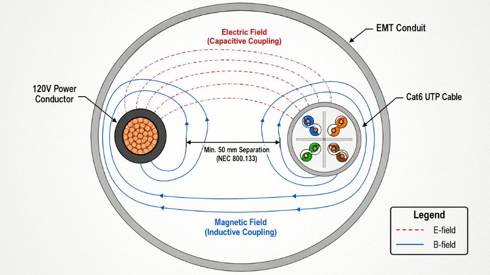
Every energized conductor surrounded by insulation acts like one plate of a capacitor. The 120V conductor’s electric field radiates outward and terminates on any adjacent conductor — including the copper pairs inside a Cat6 cable lying alongside it. The result is a noise voltage induced directly onto those data conductors.
In practice, when unshielded Cat6 shares a conduit with a 120V circuit and the physical separation is minimal — which it often is in a packed 1-inch conduit — that induced noise voltage typically runs somewhere in the 5–15 mV range. The exact figure depends on the insulation thickness of the power cable, the separation gap, the length of the parallel run, and the dielectric properties of everything between the two cables. That might not sound like much, but Gigabit Ethernet over 100BASE-T needs to maintain a signal-to-noise ratio (SNR) margin of roughly 10 dB above the noise floor. Shave that margin down with 10–15 mV of capacitively coupled interference on top of the cable’s own attenuation and near-end crosstalk, and you start seeing intermittent link drops, retransmissions, and throughput that never quite reaches what the switch reports as “1 Gbps connected.”
Inductive Coupling: The Magnetic Field Problem
Capacitive coupling is the less-discussed mechanism. Inductive coupling is usually the bigger problem in conduit runs of any real length.
A 60 Hz AC power circuit produces an alternating magnetic field that expands and collapses around the conductors 120 times per second. That changing flux cuts through the Cat6 pairs and induces a voltage according to Faraday’s law. The longer the parallel run, the more conductor length is exposed to flux linkage, and the induced voltage scales roughly linearly with run length up to the point where impedance mismatches start complicating the picture. In my experience, runs under about 15 meters in a shared conduit are often borderline — the induced noise is measurable on a good oscilloscope but may not cause obvious errors under light traffic. Once you get past 15 meters of close parallel routing, unshielded Cat6 in a shared conduit with 120V starts showing real BER degradation under sustained load, especially in anything above 40–50°C ambient (not unusual near motor drive panels or in conduit runs near industrial heating equipment).
Inductive coupling from a 60Hz power circuit scales with parallel run length and becomes measurable in unshielded Cat6 beyond approximately 15 meters of shared conduit routing.True
Faraday's law of induction predicts that induced EMF increases proportionally with the length of conductor exposed to a changing magnetic flux, consistent with field measurements and IEEE 802.3 performance testing methodology.
Why Twist Rate and Shielding Actually Fix This
Cat6 UTP manages inductive noise through the pair twist. Each twisted pair is a balanced differential system — the noise induced on one conductor of the pair is nearly identical to the noise induced on its partner, so the differential receiver at the switch or NIC subtracts them out. “Nearly identical” is doing a lot of work in that sentence. It works well for noise sources that couple symmetrically to both conductors. When a power cable is physically closer to one conductor of a pair than the other — which happens constantly inside conduit — the coupling is asymmetric, common-mode rejection fails partially, and some of that interference becomes differential noise that the receiver cannot cancel.
Cat6 FTP or S/FTP adds a metallic foil or braid that intercepts the electric field before it reaches the pairs and provides a low-impedance path to drain induced currents. That shield, when properly bonded at both ends, typically provides 15–25 dB of additional noise rejection compared to UTP in a high-EMI conduit environment. The exact improvement depends on shield continuity, bonding quality, and whether the drain wire is actually terminated to ground at the panel end — a step that gets skipped more often than it should on fast installations.
Frequency Domain: Why 60Hz Is Still a Problem at Data Frequencies
Here is something that confuses people: 60 Hz is far below the 1–250 MHz operating band of Cat6. So why does it matter?
It matters because 60 Hz doesn’t travel alone. The power waveform in any real industrial or commercial circuit carries harmonics — 120 Hz, 180 Hz, 240 Hz, and higher — generated by switching power supplies, variable frequency drives, and non-linear loads. By the time you reach the 5th and 7th harmonics (300 Hz and 420 Hz), you’re still well below the Cat6 band, but high-order harmonics from VFDs can push energy into the kilohertz range. More practically, the 60 Hz fundamental induces a low-frequency noise floor that the cable’s common-mode rejection must work against continuously. Under sustained gigabit traffic, that background noise consumes SNR margin that would otherwise absorb the cable’s own insertion loss and return loss — and cables near the 100-meter channel limit have no margin to spare.
The physics is not ambiguous. Separation rules exist because the coupling mechanisms are real, quantifiable, and cumulative with run length.
Conduit Types, Fill Ratios, and Physical Separation Strategies That Reduce Risk
The conduit you choose matters more than most installers realize — not just for code, but for how much EMI actually reaches your Cat6 pairs.
Steel Conduit vs. PVC: The Shielding Gap Is Not Trivial
Rigid Metal Conduit (RMC) and Intermediate Metal Conduit (IMC) both attenuate external magnetic fields in the 20–40 dB range, depending on wall thickness, frequency, and how well the conduit sections are bonded together. PVC ENT (the corrugated blue flex conduit you see everywhere in residential and light commercial work) offers essentially zero magnetic shielding. None. The 60 Hz field from a 120V circuit passes through it as if the conduit wall isn’t there.
In practice, this means a shared run in 1-inch Schedule 40 PVC is a fundamentally different risk profile than the same run in 3/4-inch RMC. If you’re in a plant environment with variable-frequency drives, motor feeders, or anything switching near that conduit, PVC shared routing is asking for trouble — even if the data cable is Cat6 with tight twist rates.
RMC and IMC steel conduit provide meaningful magnetic field attenuation for Cat6 runs sharing space with 120V conductors, while PVC conduit provides near-zero shielding.True
Steel conduit attenuates low-frequency magnetic fields through eddy current losses and permeability of the metal wall. PVC is non-conductive and non-magnetic, so it offers no such attenuation. This is well-established in EMC engineering and reflected in why NEC and TIA standards treat metallic raceways differently from non-metallic ones.
Conduit Fill: The Math You Need to Run Before You Pull
NEC Chapter 9, Table 1 limits fill to 40% of the conduit’s interior cross-section when three or more conductors are present. That sounds generous until you actually run the numbers.
Say you have an existing 3/4-inch EMT run carrying two 12 AWG THHN conductors for a 120V circuit. The interior area of 3/4-inch EMT is roughly 0.533 in². Two 12 AWG THHN wires at approximately 0.0133 in² each gives you about 0.0266 in² used — only around 5% fill. Looks like plenty of room. Now you want to add two Cat6 UTP cables; a typical Cat6 cable has an outer diameter of roughly 0.215 inches, so each one occupies about 0.0363 in². Adding both brings total fill to approximately 0.0992 in², or about 18.6% — still under 40%, so fill alone doesn’t prohibit it.
What that calculation does not tell you is whether the run satisfies the 50 mm separation requirement inside the conduit, or whether the EMI environment is acceptable. Fill compliance is necessary but not sufficient.
If you’re planning a longer pull — say 60+ meters — with multiple Cat6 drops branching off the same home-run conduit, the fill number can climb fast. Run the Chapter 9 math before you order conduit, not after.
Metallic Barriers Inside Large Conduit: When It’s Legitimate
For 3-inch and larger raceways, NEC 800.133(A)(1)(b) allows power and communications cables to share a conduit if a permanently installed barrier physically separates them. “Listed barrier” is the key phrase. Snap-in plastic dividers from the electrical supply house are not listed for this purpose unless the product is specifically marked and tested. Look for listed raceway dividers or dual-compartment raceway systems — manufacturers like Wiremold produce listed two-compartment surface raceway that satisfies this requirement, though those are typically for surface-mounted work rather than in-wall or underground conduit.
For large underground duct banks or industrial tray-to-conduit transitions, a steel divider plate welded or mechanically fastened into a pull box and continuing into the conduit entry is one approach field engineers use, but it requires documentation and an inspector who understands the exception. Don’t assume it’s universally accepted — call your AHJ before you design around it.
Routing When Separate Conduits Are the Only Real Answer
Sometimes you cannot share, and the constraint is physical space, not budget. Parallel runs are the worst case. If you must run data and power conduit in parallel, separation distance dominates your induced noise — even 150–300 mm of air gap between a 120V conduit and a Cat6 conduit cuts inductive coupling substantially compared to touching conduits.
Where the runs must cross, a 90-degree crossing angle is the standard recommendation from TIA-568 for minimizing coupling length. Any crossing angle above roughly 45 degrees is meaningfully better than a shallow parallel crossing. A 90-degree cross keeps the mutual inductance window to the conduit diameter, maybe 25–30 mm of exposure, versus several meters for a parallel run. Short crossing distance, short coupling path.
Grounding the Metal Conduit: Don’t Skip This
Steel conduit used as an EMI barrier only works if it’s properly grounded. NEC 250.86 requires metallic raceways to be grounded, and that bonding continuity is what allows the conduit to function as a Faraday-like shield rather than a noise re-radiator. A conduit run with a broken bond at a coupling, a corroded locknut, or a missing bonding bushing at a panel knockout can actually make interference worse in some layouts — induced currents on the conduit shell have nowhere to drain, and the conduit re-radiates toward the cable inside.
Check continuity at every coupling during installation. On long runs, use bonding locknuts rather than standard locknuts at enclosure entries.
Comparing Your Real Options
| Configuration | Code Compliance | EMI Risk | Relative Labor Cost | Relative Material Cost |
|---|---|---|---|---|
| Separate PVC conduits, minimum 50 mm apart | Compliant with separation | Moderate-High (no shielding) | Low–Medium | Low |
| Separate RMC/IMC steel conduits | Fully compliant, preferred | Low | Medium–High | Medium–High |
| Shared steel conduit with listed barrier (3-inch+) | Compliant if barrier is listed | Low–Medium | High (large conduit, barrier install) | High |
| Shared PVC conduit, no barrier | Non-compliant in most jurisdictions | High | Low | Low |
The “shared PVC, no barrier” row is what you’ll find in a lot of older light commercial buildings. It’s also what generates the most noise complaints and the most failed cable certifications. The separate steel conduit option costs more upfront — material alone might run 2–4× the PVC equivalent depending on diameter and regional pricing — but it’s the cleanest solution for any run longer than about 15 meters or any environment with load variation on the 120V circuit.
Cat6 UTP vs. Cat6 FTP vs. Cat6 SSTP: Choosing the Right Cable Construction for Mixed-Power Environments
Shield construction is where procurement decisions either protect a project or quietly set it up for failure six months after commissioning. Selecting the wrong variant isn’t just a performance issue — in a conduit shared with 120V circuits, it can mean rerunning cable through finished walls or chasing intermittent packet loss that nobody can trace back to its source.
Cat6 UTP: When Separation Is Not Negotiable
Unshielded twisted pair relies entirely on differential signaling and pair twist geometry to reject common-mode noise. That works reasonably well in a clean office environment. It does not work when power conductors are running alongside in the same raceway.
The NEC 800.133(A)(1)(b) minimum — 50 mm of air separation without a dividing barrier — exists precisely because UTP has no self-shielding. The foil is absent. The drain wire is absent. The only noise rejection mechanism is the twist rate, typically 1.5–2.5 twists per inch on a Cat6 pair, and that gives you maybe a few dB of common-mode rejection in a controlled bench setup. In a real conduit, with cables touching, routed over 30 or 40 meters, that rejection is overwhelmed. Induced noise from a 120V/60Hz circuit can push 5–15 mV onto UTP pairs depending on proximity and run length — enough to collapse your SNR margin below the 10 dB floor that Gigabit Ethernet needs to stay reliable.
Use UTP only where you can guarantee and physically verify the separation. If the separation cannot be maintained along the full route, or if the conduit fill forces cables into contact, UTP is the wrong choice regardless of cost.
Cat6 FTP (F/UTP): Practical Middle Ground for Light Industrial Runs
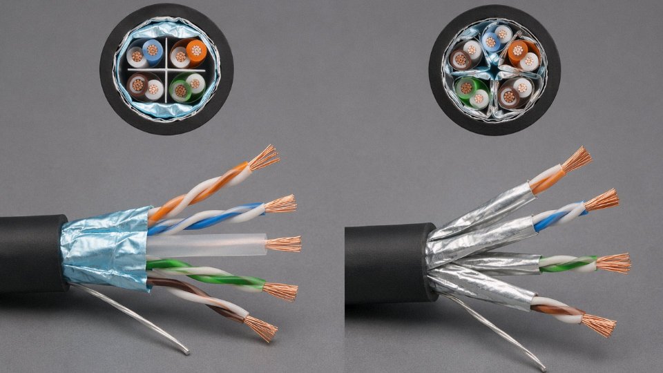
F/UTP — a single aluminum-polyester foil wrapped around all four pairs as a unit — adds meaningful shielding without the installation complexity of fully shielded constructions. Typical common-mode rejection ratio improvement runs 15–20 dB over UTP, which is enough to handle partial separation compliance or short runs in conduit near low-density 120V lighting circuits.
The foil is continuous, but it only works if the drain wire is terminated correctly at one end (usually the patch panel or switch end, to avoid ground loops). This is where FTP installations break down in practice. Installers who are used to UTP sometimes skip the drain wire termination entirely or connect both ends, which either leaves the shield floating — useless — or creates a ground loop that introduces more noise than it rejects. Neither outcome is acceptable.
FTP cable has a slightly larger outside diameter than UTP, typically 6.5–7.2 mm versus 5.8–6.2 mm for standard Cat6 UTP, so conduit fill calculations need to be revisited. It is not a drop-in swap for fill purposes.
Cat6 SSTP / S/FTP: The Correct Choice for Confirmed Mixed-Power Conduit
S/FTP — individual foil on each of the four pairs plus an overall braided outer shield — is the appropriate construction when 120V conductors are confirmed to be sharing the conduit, especially on runs longer than roughly 15–20 meters. The individual pair foils handle the differential noise coupling; the outer braid handles common-mode interference and provides mechanical protection for the foil layers during pulling.
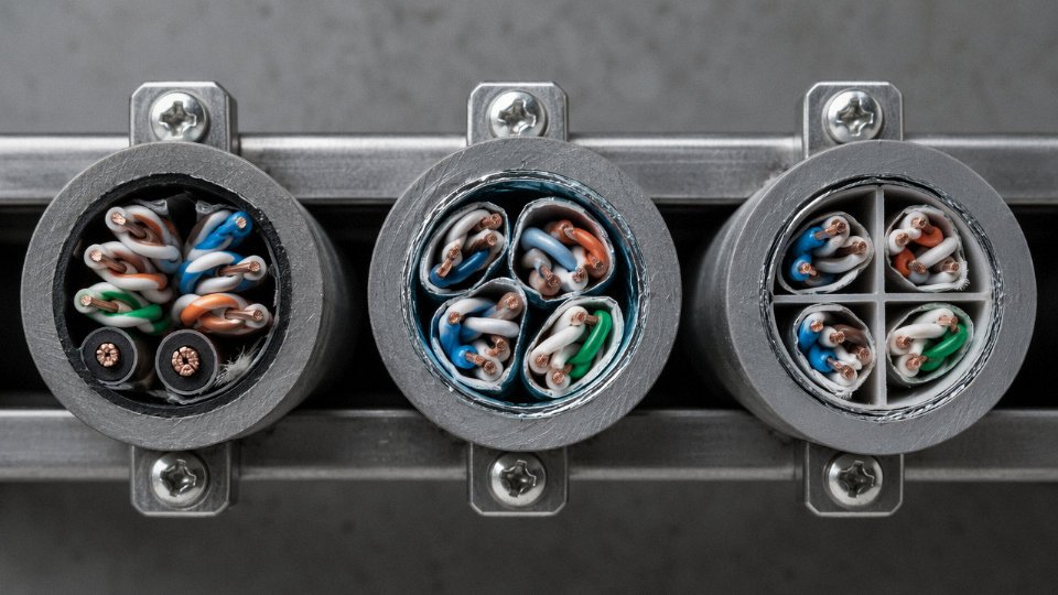
Shielding effectiveness for a properly grounded S/FTP cable typically exceeds 90 dB at 100 MHz in standardized transfer impedance tests. That is a qualitatively different level of protection than FTP, not just incrementally better. The tradeoff is real: SSTP cable outside diameter ranges from 7.5 mm to 8.5 mm depending on construction and jacket, the braid termination requires a proper shielded plug or tooled termination at both ends, and the drain wire must maintain continuity across every connection point. A single improperly crimped shielded connector drops the shield effectiveness dramatically — in my experience, to roughly the level of unshielded cable at the fault point.
The outer braid also needs a solid, low-impedance earth ground reference. Without it, the braid can act as an antenna rather than a shield. In industrial plants where grounding is inconsistent between panels, this is not a hypothetical — it is a commissioning problem that shows up regularly.
Jacket Material: LSZH vs. PVC in Conduit Applications
For conduit-routed cable, jacket choice affects fill, temperature rating, and fire code compliance. PVC jackets handle continuous temperatures up to roughly 60–75°C depending on the compound specification, which matters in conduit bundles where ambient derating applies — a fully loaded 1-inch EMT in a warm mechanical room can see sustained conductor temperatures 15–20°C above ambient. LSZH jackets typically rate similarly or slightly lower for continuous temperature but emit significantly less toxic gas in a fire event, which matters under NFPA 90A in air-handling spaces and in occupied buildings where code authorities are increasingly enforcing LSZH requirements regardless of what the minimum standard technically allows.
LSZH jackets are also somewhat harder and less flexible, which raises pulling tension requirements in long conduit runs with multiple bends. Not dramatically, but enough to matter on a 60-meter pull with three 90-degree sweeps.
Cat6 SSTP cable with a properly grounded braid shield provides adequate EMI rejection for in-conduit runs alongside 120V circuits when installed per NEC and TIA-568 termination requirements.True
S/FTP shielding effectiveness exceeds 90 dB at 100 MHz in transfer impedance testing, and NEC Article 800.133 permits shielded communications cables in closer proximity to power conductors than unshielded types when shield grounding requirements are met.
Jinda Cat6 FTP and SSTP Construction Details
Jinda’s Cat6 FTP and S/FTP cables are manufactured with precision foil overlap — minimum 25% foil overlap on the pair wraps and overall screen — and drain wire continuity is tested as a production-line parameter, not just a batch check. Both UL-listed and CE-marked jacket compounds are available depending on destination market requirements. The SSTP construction uses a tinned copper braid rather than bare copper to maintain shield integrity in humid conduit environments where bare copper braid can oxidize at termination points over time — a small detail that becomes a troubleshooting headache on a five-year-old installation.
Procurement Decision Table
| Parameter | Cat6 UTP | Cat6 FTP (F/UTP) | Cat6 SSTP (S/FTP) |
|---|---|---|---|
| Shielding effectiveness | None (0 dB) | 15–20 dB CMRR improvement | >85–90 dB at 100 MHz |
| Max operating temperature (in-conduit) | 60–75°C (PVC dependent) | 60–75°C | 60–75°C |
| NEC type listing | CM, CMR, CMP options | CM, CMR, CMP options | CM, CMR, CMP options |
| Typical OD range | 5.8–6.2 mm | 6.5–7.2 mm | 7.5–8.5 mm |
| Conduit fill impact vs. UTP | Baseline | ~10–15% larger cross-section | ~25–40% larger cross-section |
| Recommended use case | Full 50mm separation guaranteed | Partial separation, light 120V proximity | Confirmed shared conduit with 120V+ circuits |
The table is a starting point. Real conduit fill calculations need actual cable ODs from the manufacturer’s datasheet, not nominal values — manufacturing tolerances and jacket options shift the numbers enough to change whether a conduit fill calculation passes or fails.
Step-by-Step Installation Protocol for Compliant Cat6 and 120V Conduit Runs
Getting this right the first time saves you from re-pulls, failed inspections, and the special misery of chasing an intermittent network fault six months after the walls are closed up. Here is how to actually do it in sequence.
Step 1 — Site Survey and Conduit Mapping
Walk the full proposed pathway before you order anything. Measure every existing conduit you plan to share: use a conduit fill gauge or pull the existing cables and measure the OD of each conductor, then calculate occupied cross-section against NEC Chapter 9 Table 4 allowable fill. Note every 120V branch circuit in each conduit — not just the active ones, but any decommissioned conductors still present, because inspectors count them.
Document the parallel run length between power and data cables. This matters more than most installers realize. A 3-meter parallel section is a nuisance; a 30-meter parallel run at close separation can push induced noise into a range that degrades link margin. Record it all: conduit size, existing fill percentage, parallel run length, and the approximate load on each 120V circuit. That last item is relevant because a 15A circuit running close to full load produces a stronger alternating magnetic field than one idling at a few amps.
Step 2 — Code and AHJ Confirmation
Submit a written pre-installation request to the Authority Having Jurisdiction before pulling a single cable. This does not need to be elaborate — a one-page memo with a conduit layout sketch, the NEC articles you are relying on (Article 800.133 for communications, Chapter 9 for fill), and a clear description of the separation method you intend to use. Turnaround from most AHJs is roughly 5–15 business days, though jurisdictions with heavy permit backlogs can run longer. Get the response in writing. If the AHJ wants a specific separation method or additional barrier, you want that instruction before procurement, not during rough-in.
Step 3 — Material Specification
For conduit, prefer RMC or IMC steel over EMT where budget allows — the heavier wall provides better magnetic shielding and is more resistant to mechanical damage in industrial environments. EMT is acceptable for commercial work under lighter-duty conditions. For the Cat6 cable itself, use FTP as the minimum in any shared conduit run; SSTP if the parallel power run exceeds roughly 15 meters or if the circuit loading is high. Specify a pulling string rated for data cable (braided polyester, break strength appropriate to your expected tension). List bushings at every conduit entry to prevent jacket abrasion — this is one of those small details that consistently bites installers who skip it.
Step 4 — Conduit Fill Calculation
A worked example: two 12 AWG THHN power conductors (each approximately 8.6 mm²) plus four Cat6 FTP cables (each approximately 22–25 mm² depending on manufacturer). Total occupied area works out to roughly 105–117 mm². A 1-inch EMT has an allowable fill for three or more conductors of approximately 129 mm² per NEC Chapter 9 Table 4. That puts you right at the edge — around 81–91% of the limit depending on actual cable ODs. In practice, step up to 1¼-inch conduit to give yourself pulling clearance and a sensible safety margin.
Adding more cables to a conduit that is already at 40% fill does not automatically violate codeTrue
NEC Chapter 9 Table 1 permits up to 40% fill for three or more conductors; a conduit already at 40% is at the limit, not in violation — but adding any cable beyond that threshold does violate the fill rule.
Step 5 — Cable Pulling Technique
TIA-568 sets a maximum pulling tension of 110 N (25 lbf) for Cat6. That is not a lot. A snug conduit with a 90-degree sweep can eat through that budget fast, especially on runs over 20 meters. Use a pulling lubricant specifically rated for data cable jackets — standard wire-pulling compounds can swell or degrade PVC jackets over time. Keep bend radii at patch panel entries and junction boxes at a minimum of 25 mm (1 inch) for Cat6; tighter bends deform the pair geometry and introduce return loss problems that no amount of retesting will fix after the fact. Pull the data cables separately from the power conductors; do not bundle them together and drag them through simultaneously.
Step 6 — Termination, Grounding, and Bonding
For FTP and SSTP, terminate the drain wire at the patch panel end only. Single-end grounding is the correct practice — ground both ends and you create a ground loop that can actually introduce more noise than it eliminates. The shield needs a solid, low-impedance connection to the panel’s ground bar; a loose or corroded crimp here defeats the entire purpose of the shielded construction. The steel conduit itself must be bonded per NEC Article 250, with listed bonding bushings at each enclosure entry. A conduit that is physically continuous but not properly bonded at terminations is a liability for both safety and EMI performance.
Step 7 — Post-Installation Testing
Test every Cat6 link to TIA-568.2-D. The parameters that will expose EMI influence from adjacent 120V circuits are insertion loss, NEXT (near-end crosstalk), PSNEXT (power-sum NEXT), return loss, and PS ACRF (power-sum attenuation-to-crosstalk ratio, far end). If your tester shows marginal NEXT or PSNEXT results — passing, but within a few dB of the limit — that is almost always a wiring practice problem rather than a cable defect, but it can also indicate inductive coupling from the power conductors. A result that shows degraded SNR at 60 Hz harmonics is a direct fingerprint of power-line interference. Document all test results and retain them for the AHJ and for the building owner’s maintenance records. A passed test report from a Fluke DSX or equivalent field tester is the practical proof that the installation meets the channel performance requirements — and it is the only real defense you have if someone complains about network reliability six months down the line.
Industrial and Commercial Case Studies: When Shared Conduit Worked and When It Failed
Real installations rarely match the clean diagrams in certification guides. The four scenarios below represent composite patterns from actual field work — the kind of outcomes you get when decisions are made well before pulling starts, and when they aren’t.
Case Study 1 — Small Office Retrofit: Compliant Success
A 12-drop Cat6 installation in a two-story commercial office building shared 1½-inch IMC steel conduit with existing 120V fluorescent lighting circuits. Run lengths averaged 28–34 meters. The installer specified Cat6 FTP with foil shield, grounded at the patch panel end only via a drain wire terminated to the panel’s isolated ground bar — correct single-end grounding, which avoids the ground loop problem that kills a lot of otherwise decent FTP installs.
The steel IMC itself provided meaningful attenuation of external fields, and the foil shield handled residual coupling. Every drop certified to TIA-568-C.2 on first test, with insertion loss and NEXT margins comfortably above the pass threshold. What made this work: metallic conduit (not PVC), correct shield termination discipline, and run lengths short enough that cumulative noise pickup stayed manageable. The lighting load was also relatively stable — no variable-frequency drives, no switching dimmers on those circuits.
Case Study 2 — Residential Home-Run Failure: UTP Through PVC with a Kitchen Circuit
This one is instructive because the installer thought the twist rate in Cat6 UTP would be enough. Pulled standard unshielded Cat6 through ¾-inch Schedule 40 PVC conduit alongside a 20A kitchen branch circuit — dishwasher, refrigerator, microwave on the same run, roughly 18 meters parallel length. The PVC offers zero magnetic shielding. Within a week of occupancy, the homeowner reported intermittent Gigabit link drops under sustained throughput: file transfers stalling, VoIP breakup during peak kitchen use.
Diagnosis via a network analyzer showed 180Hz harmonic noise artifacts, which pointed straight to the nonlinear loads on that kitchen circuit generating odd-order harmonics. Induced noise measured in the 8–12 mV range — right at the edge of, and occasionally below, the SNR margin needed to sustain 1 Gbps reliably. Remediation required pulling the Cat6 out and re-routing through a separate PVC conduit on the opposite wall. Total remediation cost, including labor, ran to roughly 3–4× what a separate conduit would have added to the original job.
Nonlinear household loads such as microwaves and variable-speed refrigerators generate harmonic distortion that induces noise on adjacent Cat6 UTP at higher amplitudes than a simple resistive 120V load at the same current.True
Nonlinear loads draw non-sinusoidal current, producing harmonic frequencies (180Hz, 300Hz, etc.) that couple inductively into adjacent conductors. These harmonics can exceed the fundamental coupling level depending on harmonic content and proximity.
Case Study 3 — Industrial Control Panel: SSTP with Metallic Barrier
A mid-size discrete manufacturing facility ran Cat6 SSTP (braided outer shield plus individual pair foils) sharing conduit with 120V control power feeding solenoid valves and indicator lights inside a panel enclosure. The conduit was steel, and a physical barrier separated power and data conductors per NEC 800.133 exception requirements. Measured noise floor on the data side stayed below 2 mV across all test points — well inside acceptable SNR margin for Gigabit operation, even accounting for inductive spikes from solenoid switching. The SSTP construction was arguably over-spec for this environment, but given the switching noise profile, not unreasonably so.
Case Study 4 — Data Center Edge: AHJ Rejection Despite NEC Argument
The installer had a technically defensible NEC 800.133 argument and proper materials specified. The AHJ rejected the shared conduit design anyway, citing local amendments and internal policy on data center-class installations. The re-route to separate conduit stacks added roughly 15–22% to conduit materials cost and about two additional days of labor on a mid-size edge deployment. Not catastrophic, but entirely avoidable if the AHJ had been consulted during design — not during inspection.
Early AHJ engagement is not bureaucratic courtesy. It is schedule protection.
Common Failure Patterns Across All Cases
Shield grounding errors account for a disproportionate share of post-install failures — floating shields, both-end grounding on long runs, drain wire routed near noise sources. Using UTP where FTP is warranted is the second most common mistake, usually a procurement decision made without EMI context. Conduit fill violations matter more in mixed runs than in data-only runs because tight packing increases thermal rise and physical proximity between power and data cables. Parallel run lengths beyond roughly 20 meters without any mitigation (separate conduit, metallic conduit, shielded cable, or barrier) consistently produce marginal or failing noise performance.
| Case | Conduit Type | Cat6 Type | Run Length | 120V Load | Outcome | Primary Factor |
|---|---|---|---|---|---|---|
| Office retrofit | 1½” IMC steel | FTP, single-end ground | 28–34 m | Lighting circuits | Pass — first test | Metallic conduit + correct shield grounding |
| Residential kitchen | ¾” PVC Schedule 40 | UTP | ~18 m | 20A nonlinear loads | Fail — intermittent link drops | No shielding, harmonic-heavy load |
| Industrial panel | Steel, with barrier | SSTP | Short (<10 m) | Control power, solenoids | Pass — noise floor <2 mV | Barrier compliance + SSTP construction |
| Data center edge | Separate (after re-route) | — | Variable | Mixed | Pass after redesign | AHJ not consulted early; avoidable cost impact |
Frequently Asked Questions About Running Cat6 and 120V in the Same Conduit
Is it ever completely safe and code-compliant to run Cat6 in the same conduit as 120V?
Yes, but the conditions matter enormously. NEC Article 800.133(A)(1)(b) permits the cohabitation only when a physical barrier separates the conductors inside the raceway, or when the communications cable is listed for use in such environments. Without that barrier, you need at least 50 mm of separation — which is physically impossible inside most standard conduit runs. In practice, the path to a legal installation almost always runs through your Authority Having Jurisdiction. An AHJ can grant written approval for a specific installation if you demonstrate adequate shielding, separation strategy, and cable listing. Get that approval in writing before you pull a single foot of cable.
NEC Article 800.133(A)(1)(b) requires a minimum 50mm separation between communications cables and power conductors when no barrier exists inside a shared racewayTrue
This requirement is explicitly stated in the National Electrical Code Article 800.133(A)(1)(b) governing communications wiring in shared raceways with power conductors.
Does the type of 120V load matter — lighting versus motor circuits versus receptacles?
It matters more than most installers expect. A simple resistive load — incandescent or basic LED lighting — produces a fairly clean 60 Hz sine wave. Nuisance interference, yes, but manageable with shielded cable and proper grounding. Motor loads are a different animal entirely. Variable-frequency drives, HVAC compressors, and even smaller single-phase motors generate harmonics that ride up well past the fundamental 60 Hz — 3rd, 5th, and 7th harmonics landing at 180 Hz, 300 Hz, 420 Hz — and that harmonic content can land squarely inside Cat6’s operating bandwidth. A shared conduit feeding a conveyor motor controller in a light-assembly plant, for instance, is a genuinely hostile environment for unshielded Cat6 in a way that a lighting branch circuit simply is not. If your 120V circuit feeds any inductive or switching load, budget for shielded cable from the start.
What is the maximum parallel run length where shared conduit is still considered low risk?
TIA-568 guidance and practical field experience converge around 15 meters as a rough threshold for parallel runs where induced noise stays tolerable — assuming proper shielding and separation. Beyond that, cumulative inductive coupling compounds. The 15-meter figure is not a hard code number; it depends on the power conductor’s load current, the cable’s twist rate, and whether you’re running UTP or FTP. Shorter parallel runs with 90-degree crossings where possible. Every crossing is a fraction of the coupling you’d accumulate in a long parallel segment.
Can I use Cat6A instead of Cat6 to get better EMI rejection in a shared conduit?
Cat6A’s primary improvement over Cat6 is alien crosstalk performance — the pair-to-pair coupling between adjacent cables in a bundle. That’s a different mechanism from power-line EMI. Running Cat6A UTP next to a 120V circuit does not meaningfully improve your immunity to 60 Hz inductive coupling compared to standard Cat6 UTP. What actually helps is the shield. If EMI is your concern, Cat6 F/UTP or S/FTP construction addresses the problem directly. Spend the money on shielding, not on a higher category rating that solves a different problem.
Does running Cat6 next to low-voltage DC power — PoE, 12V, 24V — carry the same restrictions?
No, and this distinction trips up a lot of people. NEC Article 725 governs Class 2 limited-energy circuits, which covers most 12V and 24V DC control wiring. DC circuits produce no 60 Hz alternating magnetic field, so inductive coupling into your Cat6 pairs is negligible. PoE (whether 802.3af, at, or bt) runs on the data pairs themselves or spare pairs, so it’s already inside the cable — not an external coupling source. You still need to observe Class 2 separation rules from a code standpoint, but the EMI physics are fundamentally different from AC power proximity. In practice, a mixed Cat6-and-24V-DC conduit is rarely a performance problem.
How do I test whether EMI from a 120V circuit is affecting my installed Cat6 link?
Start with a cable certifier that has at least 1 GHz bandwidth — a Fluke DSX series unit or equivalent. Run a full certification sweep and look specifically at the SNR margin plot. A healthy Gigabit link needs roughly 10 dB of SNR headroom; if you’re seeing compressed margins in the 50–300 Hz range or intermittent fail flags on NEXT, power-line coupling is a likely culprit. For a more granular diagnosis, bring a spectrum analyzer to the patch panel with the power circuit energized and de-energized alternately. The difference in the noise floor between those two states tells you exactly what you’re dealing with. Load the circuit during testing — an unloaded motor circuit can look deceptively clean.
What are the liability implications for an electrician who installs Cat6 with 120V in a single PVC conduit without AHJ approval?
Significant, and often underestimated. A code violation under NEC 800.133 can trigger a failed rough-in inspection, mandatory rework at the installer’s cost, and a re-inspection fee that varies by jurisdiction but typically runs $150–$500 per visit. More consequentially, if a wiring fault — fire, equipment damage, data corruption — occurs in that conduit run, the absence of AHJ approval becomes a liability exposure in any insurance claim or litigation. General liability policies for electrical contractors commonly exclude losses tied to documented code non-compliance. The paper trail matters.
Can Jinda supply shielded Cat6 cables pre-cut and labeled for conduit installations with specific EMI requirements?
Yes. Jinda manufactures Cat6 F/UTP, U/FTP, and S/FTP constructions and can supply custom-cut lengths, specific jacket materials (LSZH, PVC, or CPE for industrial environments), and OEM labeling for project-specific identification. For international procurement on infrastructure or industrial projects, custom reel lengths reduce field waste and cut pulling labor. Lead times and minimum order quantities depend on the specification and destination — the technical team can work through shield construction, jacket rating, and compliance documentation (CE, RoHS, IEC 11801) for your specific project scope.
Specifying and Sourcing the Right Cat6 Cable for Conduit Installations: A Buyer’s Guide
Procurement gets treated as an afterthought on too many conduit projects. The routing plan is solid, the electrician knows the code, and then someone orders whatever Cat6 is cheapest on the distributor’s shelf. That’s where the problems start — because not all Cat6 is the same, and in a conduit run that shares a raceway with 120V circuits, the difference between a properly specified cable and a bargain-bin substitute can be the difference between a network that passes certification and one that doesn’t.
Critical Parameters to Put on Your Purchase Order
Start with shield construction. For runs anywhere near power conductors, specify F/UTP at minimum — that’s a single overall foil shield with a drain wire. If the 120V load is anything above 15A, or if you’re in an industrial environment with variable-frequency drives or ballasted lighting nearby, step up to S/FTP (individually shielded pairs plus an overall braid). Specifying “Cat6” alone on a PO tells a supplier almost nothing about EMI performance.
The drain wire matters more than people think. Specify minimum 24 AWG tinned copper. Bare copper drain wires corrode inside conduit in humid environments — I’ve seen this kill shield continuity within 18 months in a food-processing facility where condensation was a seasonal issue. Tinned is not optional for anything other than a climate-controlled office.
Foil overlap is another spec that rarely appears on a PO but absolutely should. Per IEC 61156, minimum 15% overlap is required for the foil to maintain 360-degree coverage through bending. Cable pulled through conduit gets stressed at every bend; a foil with inadequate overlap will open up at those points. Ask your supplier for the actual overlap percentage, not just a statement of compliance.
Jacket material and NEC type listing need to match your installation environment. CMR (riser) is the baseline for most commercial vertical runs. CMP (plenum) is required in air-handling spaces and costs noticeably more — roughly 30–60% premium over CMR depending on market conditions. Don’t over-specify CMP for conduit runs that don’t pass through plenum spaces; you’re paying for a flame rating you don’t need. For outdoor or direct-sun conduit, confirm the jacket carries a UV-resistance rating and an operating temperature range that covers your climate — typically −20°C to +60°C for general commercial, wider for industrial outdoor installations.
Quality Verification: What to Ask For Before You Sign the PO
Request third-party test reports for NEXT (near-end crosstalk), insertion loss, and return loss per TIA-568.2-D at 250 MHz. Not the manufacturer’s own summary sheet — the actual test data, ideally from a Spirent, Fluke Networks, or equivalent instrument. UL or ETL listing confirmation should come as a file number you can verify independently, not just a mark printed on the jacket. For projects shipping into the EU or any RoHS/REACH-regulated market, get the compliance documentation in writing before the order ships; retrofitting this paperwork after the fact is a genuine headache.
A Cat6 F/UTP cable with a 24 AWG tinned copper drain wire and minimum 15% foil overlap provides measurably better shield continuity after conduit installation than a cable without these specifications.True
Shield continuity depends on foil integrity through bending and the drain wire maintaining contact; tinned copper resists corrosion, and adequate overlap ensures coverage is maintained at bend radii typical of conduit installations.
Evaluating a Manufacturer’s Production Capability
Any serious supplier should be able to provide electrical performance data at 250 MHz, not just a marketing spec sheet. Ask specifically for pair twist rate consistency reports from production QC — twist rate is what drives NEXT performance, and a manufacturer that doesn’t track it lot-to-lot is cutting corners somewhere. Shield continuity test pass rates from production records are another useful signal; a well-run line should be running above 99.5% first-pass.
Vertical integration matters for consistency. A manufacturer that draws its own copper from rod stock controls the conductor diameter tolerance end-to-end. Nominal 23 AWG conductor should measure 0.573mm ± 0.005mm. Undersized conductors are the most common quality failure in low-cost Cat6 — the jacket looks right, the print says 23 AWG, but the actual copper is lighter and the insertion loss fails at longer runs or elevated temperatures.
Watch for these red flags specifically: foil overlap below 15%, drain wire absent on an FTP cable (this happens — the foil is there but it’s floating), jacket wall thickness under 0.5mm (measure it on a cross-section, not just the OD), and conductor diameter that measures light on a micrometer. A low price that depends on one of these shortcuts isn’t a deal.
Jinda manufactures Cat6 cable across five production bases in China with ISO 9001 and ISO 14001 certification and handles copper drawing through finished cable in-house — which means conductor diameter consistency is controlled at the source rather than bought in from a third party. With export experience across 50-plus countries and the ability to handle custom OEM packaging and project-specific labeling, they’re set up for the kind of bulk procurement and documentation requirements that international projects and regulated markets actually demand.
What to Send When You Request a Quote
Give the supplier real information: conduit type and trade size, total run length and number of drops, the 120V load characteristics (circuit amperage, load type — resistive, inductive, or switching), and your local code requirements or inspection authority. A supplier who responds to that with a specific product recommendation and supporting test data is one worth dealing with. A supplier who just sends a price per foot without asking any of those questions is probably not thinking about your application at all.