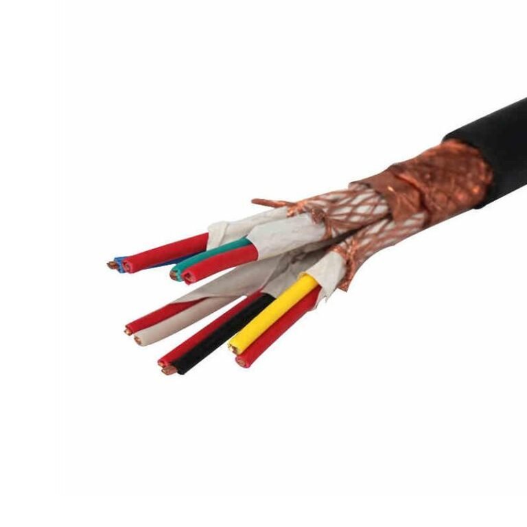
Wiring crews under schedule pressure — and frankly, most of them are — will sometimes pull power and control conductors through the same conduit simply because there’s room. On the surface it looks fine. Then the 24 V DC PLC inputs start reading phantom signals during motor starts, a proximity sensor misfires, and the maintenance team spends a shift chasing a fault that isn’t mechanical at all. Induced noise on control wiring causes nuisance trips, corrupted fieldbus data, and in worst cases, unintended actuator movement. The rework cost to re-pull separated conduits after commissioning routinely runs several times the original labor saving.
Under NEC Article 300.3(C)(1), power and control wires can share a conduit, but only when every conductor in that raceway is insulated for the highest voltage present. IEC 60364-5-52 sets a minimum 50 mm separation for parallel tray runs above 1 kV; in practice, most industrial motor-control installations maintain 150–300 mm between 480 V feeders and 24 V DC control circuits to keep induced interference within acceptable limits.
What makes this genuinely complicated isn’t the code language — it’s the gap between what’s technically permitted and what actually holds up on a running production line with variable-frequency drives, solenoid coils switching at 10 Hz, and a cable tray that was never quite laid out the way the drawings said it would be. The answer depends on voltage class, cable type, grounding practice, and how noise-sensitive your control architecture really is.
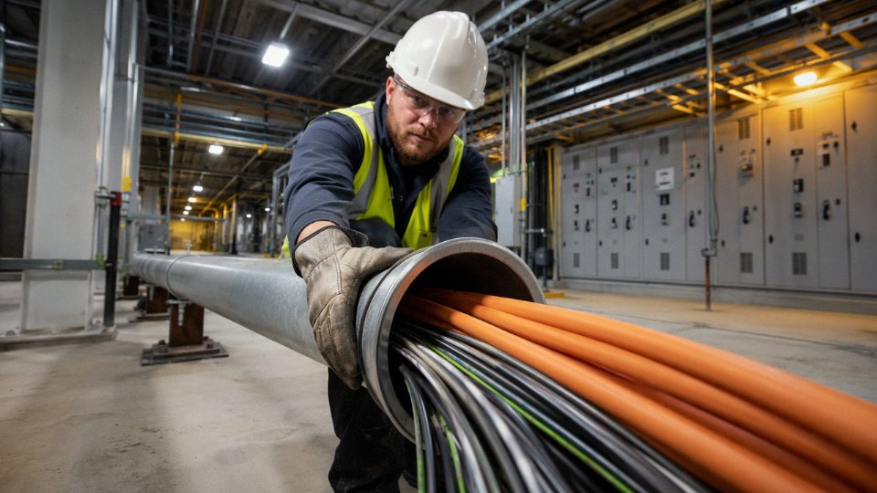
Defining the Two Circuit Types: What Counts as Power Wiring Versus Control Wiring
Getting this classification wrong is where most installation mistakes start. Not at the conduit-fill calculation, not at the separation distance — at the point where someone looks at a wire and makes an incorrect assumption about what category it belongs to.
Power Circuits: Current That Does Work
Power circuits are conductors carrying current directly to a load that consumes it — motors, resistance heaters, luminaires, VFDs, compressors, welding equipment. Voltage ranges typically run from 120 V AC on single-phase branch circuits up through 480 V AC (the most common industrial utilization voltage in North America), 600 V, and into medium-voltage territory from roughly 2.4 kV to 15 kV AC for large motors and distribution feeders. Current can be anywhere from a few amperes on a small fractional-horsepower motor to thousands of amperes on a main service entrance or bus tie.
In the NEC framework, these circuits are governed by Articles 210 (branch circuits), 215 (feeders), 230 (services), and 600 (electric signs and outline lighting, where it gets messy). IEC 60364-4 covers the equivalent ground internationally. The defining characteristic isn’t just voltage — it’s that the conductor is delivering energy to produce physical output: rotation, heat, light.
Control Circuits: Signals That Command Power Equipment
Control circuits carry low-energy signals whose job is to tell power equipment what to do — start, stop, reverse, ramp up, hold position. Relay coils, PLC discrete outputs, solenoid valve actuators, pilot lights, motor starter auxiliary contacts. Typical operating voltages are 120 V AC (still very common in older panels and heavy industrial relays) and 24 V DC, which has become the de facto standard for most modern PLC I/O. Some legacy systems still use 48 V DC or 125 V DC in substation control.
NEC Article 430, Part VI specifically addresses motor control circuits and sets the rules for overcurrent protection of the control conductors themselves — a detail that surprises people who assumed a 14 AWG control wire just follows the same rules as a 14 AWG branch circuit conductor. IEC 60204-1 (Safety of Machinery — Electrical Equipment) covers control circuit requirements in a machine context and is the standard most machine builders exporting to Europe will be working against.
The Third Category That Causes the Most Problems
Here’s where the classification question gets genuinely complicated: instrumentation and signal cables. These are not control wiring in the usual sense. A 4–20 mA analog loop operates at millivolt-level signal differentials across a 250-ohm burden resistor. An RS-485 communications cable carries differential voltages in the range of 1.5 V to 5 V. Thermocouple extension leads may be resolving temperature differences that correspond to signal changes of microvolts. These circuits are categorically more sensitive to electromagnetic interference than a 24 V DC discrete control wire, and treating them as interchangeable is a reliable way to produce sensor drift, communication faults, or outright instrument damage.
An engineer who runs a shielded 4–20 mA flow transmitter cable alongside a 480 V drive output in the same conduit — rationalizing it as “they’re both low-current signal wires” — may find that the drive’s switching noise couples into the analog loop and turns a clean process signal into something that looks like the process is hunting continuously. The DCS operator sees instability. The process engineer suspects the transmitter. The maintenance tech replaces the transmitter. Nothing changes, because the cable routing was the problem the whole time.
NEC Article 430 Part VI governs overcurrent protection requirements for motor control circuits separately from the branch circuit conductors feeding the motorTrue
NEC 430.72 establishes specific overcurrent protection rules for control circuit conductors that differ from standard branch circuit protection rules under Article 210, based on conductor size and whether the control circuit leaves the motor control enclosure.
Quick-Reference Classification Table
| Circuit Type | Typical Voltage | Typical Current | Primary Standard | Noise Sensitivity |
|---|---|---|---|---|
| Power (branch/feeder) | 120 V AC – 15 kV AC | 15 A – several kA | NEC Art. 210/215/230; IEC 60364-4 | Low |
| Control (discrete) | 24 V DC, 120 V AC | 10 mA – 5 A | NEC Art. 430 Part VI; IEC 60204-1 | Low–Moderate |
| Instrumentation/signal | mV – 5 V DC (signal level) | 4–20 mA or less | ISA-5.1; IEC 60364-4-444 | High |
Why the Product Families Reflect These Divisions
Cable manufacturers that take this seriously — and any manufacturer supplying to real industrial projects should — structure their product families around these three categories rather than lumping them together. Jinda’s catalogue separates power cables (YJV, XLPE-insulated constructions for energy distribution), control cables (KVV, KYJV — designed for the mechanical and electrical demands of panel wiring and multi-conductor control runs), and instrumentation cables (DJYPVP and similar shielded twisted-pair constructions built specifically for signal integrity). That’s not marketing segmentation; it reflects the fact that the shielding, insulation grade, conductor stranding, and jacket compound are genuinely different between a cable that needs to survive 600 V continuously and one that needs to preserve a 4 mA signal in an electrically noisy enclosure.
Misclassifying a circuit at the design stage usually doesn’t announce itself as a classification error. It shows up later as a nuisance fault that takes three shifts to trace, or as an instrument calibration that drifts every time the adjacent VFD ramps up. Getting the taxonomy right before pulling wire is the cheapest fix available.
NEC and IEC Code Requirements: What the Regulations Actually Permit and Prohibit
The short answer most engineers want is “yes, sometimes” — but the conditions attached to that answer are where installations go wrong, inspections fail, and interference problems get blamed on the wrong thing for months.
NEC 300.3(C)(1): The Insulation Voltage Rule
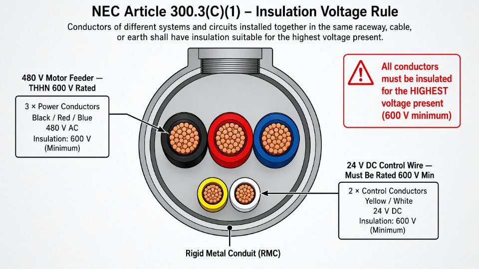
NEC Article 300.3(C)(1) is the foundational permission. Conductors of different systems — different voltage levels, different circuit types — may share the same raceway, cable, or enclosure, but only when every conductor inside that raceway is insulated for the highest voltage present. Not the voltage of its own circuit. The highest voltage in the assembly.
Work through it concretely: a 480 V, three-phase motor feeder sharing a rigid metal conduit with 24 V DC control wiring. The 24 V wire must carry insulation rated for at least 600 V — which in North American practice typically means THHN or THWN, both rated 600 V. Standard 24 V instrument wire pulled from a drum of unrated or 300 V-rated cable does not qualify. This is the mistake that gets caught at rough-in inspection more than any other on mixed-voltage projects, and fixing it after conduit is embedded in a slab is a genuinely ugly situation.
NEC Article 725: Class Matters More Than Voltage
Article 725 draws a hard line based on circuit class, not just voltage. Class 1 remote-control and signaling circuits — rated up to 600 V — are permitted to share a raceway with power conductors under the 300.3(C)(1) conditions above. That covers most PLC output wiring to motor starters, solenoid valves, and similar industrial loads.
Class 2 and Class 3 circuits are a different story. These are the low-power instrumentation circuits — typically ≤150 V and ≤100 VA for Class 2 — that power sensors, 4–20 mA analog loops, and similar field devices. They generally cannot share a raceway with power wiring. The reasoning is partly EMC, partly shock hazard (a fault from a power conductor into an unprotected Class 2 circuit could energize field devices or instrument enclosures at dangerous voltages), and partly the inherent energy-limitation that defines Class 2 in the first place. There are specific exceptions, but they require either physical barriers inside the raceway or the use of cable specifically listed for mixed installation.
Class 2 and Class 3 circuits cannot share a conduit with power wiring under NEC Article 725 without specific listed exceptions.True
NEC 725.136 restricts Class 2 and Class 3 circuit cables from occupying the same cable, enclosure, or raceway as Class 1, electric light, power, or non-power-limited fire alarm circuits, with enumerated exceptions.
NEC 430.74: The Motor Control Exception
This one gets overlooked. NEC 430.74 explicitly permits motor control circuit conductors to share an enclosure, raceway, or cable with the motor circuit conductors they control. So running the 120 V control transformer secondary wiring — the coil circuit for the motor starter — in the same conduit as the 480 V motor feeder is code-compliant, provided the insulation voltage rule is still satisfied. In practice, this exception is what makes compact MCC wiring possible. Without it, every motor feeder conduit would need a parallel raceway just for the coil circuit, which is neither practical nor necessary.
IEC 60364-5-52 and IEC 60204-1: Performance-Based Segregation
IEC takes a noticeably different philosophical approach. Where NEC gives you specific rules per circuit class, IEC 60364-5-52 and IEC 60204-1 ask whether the installation achieves adequate safety and electromagnetic compatibility — and then offers separation distances as one acceptable method to get there.
IEC 60204-1 Clause 14 categorizes cables into voltage bands: Band I covers extra-low voltage (≤50 V AC or ≤120 V DC), and Band II covers circuits up to 1 kV. The standard specifies that Band I and Band II cables should be separated unless the Band I cables are rated for the higher band voltage or are individually screened. For parallel runs in cable trays, IEC 60364-5-52 recommends a minimum 50 mm separation between power cables above 1 kV and control or signal cables. In industrial motor control applications running 480 V feeders alongside 24 V DC control wiring, accepted practice — and what most experienced machine builders specify by default — sits in the 150–300 mm range, depending on run length, whether the power conductors are shielded, and what level of noise immunity the control system demands.
The IEC performance-based framework gives more flexibility than NEC in some respects, but it also puts more engineering judgment on the designer. That can be a problem when documentation is thin or when a machine ships internationally and the receiving country’s AHJ applies its own interpretation.
The AHJ and Insurance Layer
Even when both NEC and IEC permit co-routing, the local Authority Having Jurisdiction can impose stricter requirements, and in industrial facilities with process insurance underwriters involved, those underwriters sometimes go further still. Pharmaceutical plants, chemical facilities, and anywhere with a process safety management program tend to have internal standards — engineering standards, not codes — that prohibit mixing power and control wiring entirely, regardless of insulation ratings. Getting a verbal approval from an AHJ inspector is not documentation. Get it in writing before you pour conduit or seal a raceway.
The Physics of Electromagnetic Interference: Why Proximity Between Power and Control Wires Causes Real Damage
Most engineers who have spent time on a working plant floor have seen it: a perfectly commissioned PLC analog loop starts drifting after a VFD gets installed nearby, or a 4–20 mA level transmitter reads high every time a large motor starts. The instinct is to blame the instrument. Usually, the real culprit is the cable routing.
Capacitive Coupling: The Invisible Plate Capacitor
Any two conductors separated by an insulating medium form a capacitor. When a 480 V power conductor runs parallel and close to a 24 V DC control wire, the power conductor acts as one plate, the control wire as the other, and the insulation (plus any air gap) as the dielectric. Under steady-state 60 Hz conditions, the coupled current is small enough to be ignorable in most cases. The problem is transients.
Variable frequency drives are the worst offenders here. A modern VFD switching at a carrier frequency of 4–16 kHz — common in HVAC-duty and conveyor drives alike — produces voltage rise times well under 1 microsecond on the motor feeder. The noise voltage injected into an adjacent control conductor is proportional to the mutual capacitance and the rate of voltage change (dV/dt). With a fast-switching drive, that dV/dt can be 10 to 100 times greater than what a plain 50/60 Hz sine wave produces. The capacitively coupled noise spikes don’t look like a clean offset; they look like sharp, irregular transients that can false-trigger digital inputs or corrupt analog readings in ways that are genuinely hard to reproduce during troubleshooting.
Inductive Coupling: Why Long Parallel Runs Are a Specific Problem
A current-carrying conductor generates a magnetic field around it. When that current alternates, the field collapses and rebuilds sixty times per second — or thousands of times per second in a VFD circuit. Any nearby conductor sitting inside that changing flux will have a voltage induced into it. The magnitude depends on the mutual inductance, which is directly proportional to the length of the parallel run and inversely proportional to the spacing between conductors.
This is why the 150–300 mm separation rule for motor control applications isn’t arbitrary. Halving the spacing roughly doubles the mutual inductance. Running a 10-meter parallel segment instead of 2 meters multiplies the induced voltage by roughly five. A 480 V, 30 A motor feeder running 10 meters alongside an unshielded 4–20 mA analog cable at 50 mm separation can realistically induce noise in the range of several millivolts to tens of millivolts into that signal loop. On a 20 mA full-scale signal — where 1 mA represents 5% of span — even 1–2 mA of noise current works out to a ±1–5% measurement error. For a flow meter driving a PID loop, that’s not a nuisance; that’s a process control problem.
A VFD-driven motor feeder produces significantly higher electromagnetic interference in adjacent control wires than a direct-on-line starter at the same voltage and current rating.True
VFDs switch at carrier frequencies of 2–16 kHz with sub-microsecond rise times, producing dV/dt values orders of magnitude higher than the gradual sinusoidal voltage changes from a DOL starter. This dramatically increases capacitive coupling into nearby control and signal cables.
Conducted Interference: The Ground Reference Problem
Capacitive and inductive coupling are the mechanisms most engineers think about. Conducted interference through shared grounding is less intuitive and more insidious. In a plant where multiple panels share a common ground bus, the return current from a large motor or a bank of solenoids flows back through the ground conductor. If the analog common or signal reference for a sensitive instrument shares any portion of that ground path, the voltage drop caused by high return currents raises the noise floor of the entire measurement system. You’ll see this as a slowly drifting zero, an apparent offset that changes with production load, or false triggering on a 24 V DC input that works fine during a weekend shutdown. Ground-loop-induced errors are among the harder faults to trace without a current clamp and some patience.
Why Shielded Cable Helps — and Where It Falls Short
A foil or braided shield, properly grounded at a single point, does attenuate capacitive coupling effectively. The shield intercepts the electric field and drains the induced charge to ground before it reaches the signal conductor. Against magnetic field induction, though, a simple foil shield offers limited protection — you’d need a heavy braided shield or a dedicated instrument cable with a steel armor layer to make a meaningful dent in the inductive component. In practice, shielded cable is a necessary mitigation, not a substitute for separation. Running a shielded analog cable at 25 mm from a VFD output feeder is still a bad idea, even with a perfect single-point ground. The physics doesn’t care about your cable spec sheet if you ignore the spacing.
Physical separation is the primary defense. Everything else — shielding, filtering, twisted pairs — is a supplement.
Practical Separation Rules and Installation Methods That Satisfy Both Code and EMC Requirements
The cleanest answer to the shared-conduit question is also the simplest: run separate conduits. One metallic conduit for power feeders, a second for control and signal wiring. Steel IMC or rigid conduit does provide a measurable degree of magnetic shielding — the ferrous wall attenuates low-frequency fields — and it gives you a continuous, low-impedance ground path that helps with fault clearing. But do not let that reassure you too much when a VFD is involved. Variable-frequency drives generate high-frequency switching transients (typically in the 2–20 kHz range, with harmonic content well above that) that propagate along the output conductors regardless of conduit material. Distance is the real mitigation there, not the conduit wall. In practice, I’ve seen plants route VFD output cable in grounded steel conduit right alongside 24 V DC PLC I/O wiring and then spend weeks chasing phantom input faults before someone finally separates them. Separate conduits, routed with at least 300 mm of air between them where they run parallel, would have prevented the entire episode.
Cable Tray Zoning When Conduit Isn’t Practical
Open ladder tray is common in process plants and large motor control installations, and it’s perfectly code-compliant — as long as you zone it properly. IEC 61537 (cable tray systems) and NEMA VE 1 both recognize that mixed-voltage installations require either physical dividers or enforced separation distances within a tray. The practical standard for industrial motor control environments: maintain at least 150–300 mm of horizontal separation between 480 V AC power bundles and 24 V DC control cables. Where that gap isn’t achievable, a grounded metal divider plate running the full length of the tray run is the correct fix. The divider needs to be bonded at both ends; a floating divider is largely decorative from an EMC standpoint.
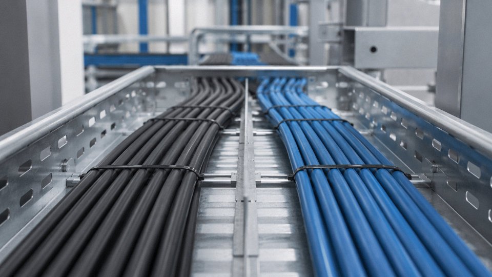
Crossing at Right Angles
When power and control cables have to cross — and in any real plant, they will — route them perpendicular to each other. A 90° crossing minimizes the length of parallel run to essentially zero, which collapses mutual inductance to near nothing. This costs nothing beyond the discipline to enforce it during installation. Mark it on your routing drawings, call it out in your installation specification, and check it during walkdown. It’s one of those rules that’s easy to ignore when a cable puller is working fast at the end of a shift.
Conduit Fill and Derating — an Important Distinction
NEC Table 310.15(B)(3)(a) requires ampacity derating when more than three current-carrying conductors share a conduit. Adding 18 AWG control conductors carrying a few milliamps of PLC signal current to a conduit that already has three power conductors does not materially affect heat buildup — those wires carry negligible current and contribute almost nothing to thermal load. Technically they are current-carrying conductors if they carry load current, so classify carefully. The derating problem shows up when you add parallel power circuits, not when you pull in a handful of control leads.
Adding low-current control conductors (signal or 24 V DC) to a conduit already containing three power conductors does not trigger meaningful NEC ampacity derating in typical industrial installations.True
NEC Table 310.15(B)(3)(a) derating applies to current-carrying conductors; low-level control/signal wires contribute negligible heat load. However, all conductors must be counted for conduit fill calculations, and any conductor carrying load current is technically current-carrying — classification matters.
Cable Selection: Getting the Spec Right Before the Wire Goes In
For any control wiring that shares a raceway with power conductors, specify 600 V-rated insulation regardless of the operating voltage. NEC 300.3(C)(1) is explicit: all conductors in a shared conduit must be insulated for the highest voltage present. Running a 24 V DC wire with 600 V-rated insulation isn’t over-engineering; it’s the minimum code-compliant choice.
For analog signals — 4–20 mA loops, thermocouples, RTD circuits — and for any serial communication cable running near power wiring, individually shielded twisted pairs (ISTP) are not optional. An overall shield alone won’t protect individual pairs from cross-talk in a multi-pair cable. Jinda’s DJYPVP instrumentation cable series addresses exactly this: individual foil shields on each pair plus an overall shield, designed for precisely these mixed-environment routing situations where you can’t always achieve ideal separation.
For VFD output runs specifically, use a dedicated VFD-rated cable with symmetrical ground conductors and a continuous overall shield bonded at the drive end. This contains high-frequency noise at the source rather than letting it radiate into adjacent control wiring. Jinda’s KVV and KYJV control cable series carries 600 V-rated PVC or XLPE insulation across the range, meeting the voltage-withstand threshold required by both NEC 300.3(C)(1) and IEC 60364-5-52 for shared-raceway installations — which matters when your project has to satisfy an international certifier and a North American AHJ on the same installation.
Special High-Risk Scenarios: VFD Output Cables, Hazardous Locations, and High-Voltage Systems
The general guidance covered so far — maintain separation, match insulation ratings, follow code — gets you through maybe 80% of industrial installations. The remaining 20% involves conditions where the consequences of getting it wrong aren’t a nuisance trip or a noisy signal. They’re arc flash incidents, SIL certification failures, and explosions. These scenarios demand their own treatment.
VFD Output Cables: The Most Electrically Aggressive Wire in Your Plant
A variable frequency drive output cable is not a normal power conductor. Between the drive’s output terminals and the motor, you have high-frequency switching transients superimposed on the fundamental AC waveform — pulse-width modulation switching at anywhere from 2 kHz to 16 kHz depending on the drive and its configuration. The common-mode voltages and dV/dt rates on that cable can reach several hundred volts per microsecond. Put a 24 V DC control wire within 150 mm of that cable in a shared tray and you will induce noise that causes erratic PLC inputs, false encoder counts, and analog signal drift that’s genuinely difficult to diagnose because it appears intermittent.
IEEE 519 and most VFD manufacturer installation guidelines require VFD output cables to run in dedicated conduit or tray, isolated from all other wiring.True
IEEE 519 addresses harmonic limits and VFD manufacturers such as ABB, Rockwell, and Siemens explicitly state in their drive installation manuals that output cables must be segregated from control and signal wiring to prevent EMI coupling.
In practice, this means a separate conduit. Not a separate compartment in the same tray, not a divider plate — a separate conduit, grounded at both ends through a low-impedance path. Shielded VFD cable (with a dedicated symmetrical ground conductor) is the correct cable type; standard THHN pulled through conduit is a poor substitute even if it’s the cheaper option at procurement time.
Hazardous Classified Locations
NEC Articles 500–516 and the IEC 60079 series impose explosion protection requirements that make co-routing impractical even in cases where it isn’t outright prohibited. In a Division 1 or Zone 1 area — where flammable atmosphere can be present during normal operation — conduit seals are mandatory at specific intervals and at enclosure entries. Stuffing more conductors into that conduit to share it between power and control circuits increases fill, complicates seal installation, and can void the ATEX or IECEx certification of the explosion-proof equipment if the sealing compound isn’t applied correctly for the actual conductor count and sizes present.
Beyond the mechanical issue, the certifications for intrinsically safe (IS) circuits explicitly prohibit running IS control wiring in the same conduit as non-IS power wiring. That’s not a gray area.
Medium-Voltage Systems
At voltages above 1 kV, the physics and the code converge on the same answer: separate raceways, full stop. NEC Article 310 and IEC 60364-4-41 both establish creepage and clearance requirements at medium voltage that simply cannot be satisfied inside a shared conduit with low-voltage control wiring. The fault energy available on a 4.16 kV or 13.8 kV feeder is high enough that an insulation failure doesn’t just damage equipment — it destroys it, and potentially injures people nearby. There is no installation method that makes co-routing acceptable here.
SIL-Rated Safety Circuits
IEC 61508 and IEC 62061 create a category of circuit that most plant electricians don’t encounter until a safety systems integrator shows up and starts asking uncomfortable questions about cable routing. Emergency stop loops, safety relay circuits, and fire suppression triggers that carry a SIL 2 or SIL 3 rating must be routed to prevent common-cause failures — meaning a single event (a power fault, a ground fault, induced noise) cannot simultaneously affect both the hazardous process and the safety function designed to stop it.
Running an e-stop circuit alongside a 480 V motor feeder in the same conduit creates exactly that vulnerability. If a fault on the power conductor induces a spurious signal that masks a genuine fault condition, or if a ground fault disables both circuits, the SIL certification of the entire safety loop is compromised. Insurance auditors and TÜV assessors will ask to see the routing documentation. If it doesn’t exist, the certification doesn’t hold.
Document the Rationale, Every Time
For any installation that doesn’t fit cleanly into standard guidance — a borderline separation distance, a shared tray near a VFD, a classified location with mixed circuit types — write it down. A brief separation rationale in the project’s electrical design basis or EMC plan, referencing the applicable code clauses and the decision made, protects the installing contractor, the engineer of record, and the plant owner when the facility inspector shows up, when the insurance carrier reviews a claim, or when a process safety audit starts pulling cable routing drawings. In my experience, the installations that cause the most expensive disputes are rarely the obviously wrong ones — they’re the undocumented borderline calls that nobody can reconstruct two years later.
Step-by-Step Decision Framework: How to Evaluate Any Conduit Sharing Scenario Before You Pull Wire
Most wiring mistakes happen before a single conductor enters the raceway. Someone makes a judgment call at the conduit schedule stage — “it’s just control wire, it’ll be fine” — and three months later the maintenance crew is chasing phantom faults in a PLC analog input at 2 a.m. The framework below turns the technical content from the earlier sections into a repeatable checklist you can run through on any project, from a single conduit stub-up to a full MCC room home-run design.
Step 1: Classify Every Circuit Proposed for That Conduit
Write it down. Do not do this in your head. List every circuit you are considering routing together, then assign three attributes to each: voltage class (extra-low voltage below 50 V AC / 120 V DC, low voltage up to 1 kV, medium voltage above 1 kV), circuit type (power feeder, motor branch circuit, NEC Class 1/2/3 control, instrumentation/signal, or safety/emergency), and sensitivity level (immune, susceptible, or highly susceptible to interference).
A 480 V motor feeder is low-voltage by definition but it is a power circuit and it generates significant inductive and capacitive fields. A 24 V DC proximity sensor signal cable is extra-low voltage but highly susceptible — a few millivolts of induced noise can corrupt a measurement. Getting the sensitivity classification right matters more than most engineers expect, especially with analog signals below 5 V or 4–20 mA loops running over long distances.
Step 2: Check Hard Prohibitions Before Anything Else
This step has no nuance. Pull up NEC Article 725 and verify the class restrictions for every control circuit. NEC 300.3(C)(1) requires that all conductors sharing a raceway be insulated for the highest voltage present — no exceptions, no cost-benefit discussion. If you have a 480 V circuit and a Class 2 control circuit proposed for the same conduit, the answer is separate conduits, full stop. Similarly, IEC 60364-5-52 and IEC 60204-1 both contain segregation clauses for certain circuit combinations. Check which standard governs your project and read the relevant clause rather than relying on memory. If a hard prohibition applies, stop here and redesign. There is nothing to optimize.
Step 3: Assess EMC Risk
If any power circuit in the proposed conduit is a VFD output, assign maximum EMC risk immediately and treat the entire run as incompatible with any signal or control wiring — period, regardless of run length or shielding. For conventional power circuits, parallel run length drives risk more than almost any other variable: runs beyond roughly 3 meters between a power feeder and a signal cable will almost always produce measurable coupling. Shorter runs in the 1–2 meter range are sometimes acceptable with proper mitigation, but that judgment depends on the signal type and frequency. Any analog measurement cable — thermocouple extension, 4–20 mA transmitter, RTD lead — should be classified as highly susceptible by default.

Step 4: Apply the Mitigation Hierarchy in Order
Start with the highest protection level and work down only as far as the risk level genuinely permits. Separate metallic conduits give you the best isolation and are often the right answer even when technically not required — conduit is cheap compared to a troubleshooting call. If a shared tray is unavoidable, a metal divider between compartments handles most low-voltage situations. Minimum separation distances of 150–300 mm between 480 V feeders and 24 V DC control wiring apply when sharing an open tray; that range depends on whether the control cable is shielded and whether the power circuit carries steady-state or switched load. Crossing at 90° where runs must intersect reduces coupling dramatically. Shielded and properly grounded conduit is a supplemental measure, not a substitute for separation.
Do not let cost pressure collapse this hierarchy prematurely. One failed temperature sensor in a batch process can cost more than the labor to pull a separate conduit.
Step 5: Verify Insulation Voltage Ratings
Pull the data sheets for every cable proposed for the shared conduit. Confirm the voltage rating stamped on the insulation meets or exceeds the highest voltage present in that raceway. Document the rating — manufacturer, part number, rated voltage — in the conduit schedule. This sounds obvious but gets skipped regularly on fast-moving projects where someone substitutes a cable from stock without checking the spec sheet.
NEC 300.3(C)(1) requires all conductors sharing a raceway to be insulated for the highest voltage present in that racewayTrue
NEC 300.3(C)(1) states that conductors of different systems occupying the same raceway must all have insulation rated for the maximum circuit voltage present, ensuring no conductor is underrated for the electrical stress it will experience.
Step 6: Record, Document, and Get It Reviewed
Complete a conduit schedule — a real one, not a markup on a napkin — showing every circuit in every conduit, the voltage class and insulation rating of each conductor, and the separation or mitigation method selected. Before any wire gets pulled, that schedule should be reviewed by the engineer of record. On permitted projects, submit it to the authority having jurisdiction as well. Changes made after installation are expensive. Changes made after a failed inspection or a nuisance-trip investigation are more expensive still.
Run this six-step sequence on every conduit grouping that mixes anything other than identical circuit types. It takes maybe fifteen minutes per conduit group on a typical motor control project. That is a reasonable investment given what a wiring error can cost in rework, downtime, or regulatory delay.
Frequently Asked Questions About Running Power and Control Wires Together
Can 24 V DC control wires share a conduit with 120 V AC power wires?
Technically, yes — but the answer has conditions attached that matter in practice. NEC 300.3(C)(1) permits it as long as every conductor in that conduit is insulated for the highest voltage present, which in this case is 120 V AC. Most quality control cables are already manufactured to a 600 V insulation rating, so that hurdle is usually easy to clear.
The part engineers underestimate is the EMC side. A 120 V AC power conductor running parallel to a 24 V DC signal circuit will induce noise through capacitive and inductive coupling, and the longer the parallel run, the worse it gets. On a 3 m run feeding a single relay, you probably won’t notice anything. On a 30 m run feeding a PLC analog input card reading a 4–20 mA process signal, you may spend days chasing ghost faults before realizing the conduit is the problem. Assess the sensitivity of the control circuit before you decide, not after.
Is it ever acceptable to run VFD output cables with control wiring?
No. This is one of the few areas where the answer is unambiguous regardless of conduit material, cable shielding, or run length. VFD output cables carry high-frequency switching noise — carrier frequencies typically in the 2–16 kHz range with fast voltage rise times — and that noise couples aggressively into anything nearby. Even a short shared run of a few meters can corrupt PLC I/O signals, cause erratic sensor readings, or in some cases damage instrument inputs. VFD output cables belong in their own dedicated conduit, full stop.
VFD output cables should always run in a dedicated conduit, separate from control and signal wiring.True
VFD drives generate high-frequency switching transients that couple strongly into adjacent low-voltage control circuits; this is documented in IEC 61800-3 and consistently recommended by drive manufacturers and EMC engineers.
Does metal conduit eliminate the need for cable separation?
It helps, but it is not a substitute. Steel conduit provides a low-impedance ground return path and does reduce capacitive coupling. What it does not do is block magnetic fields from power conductors, and magnetic induction is the dominant interference mechanism in most industrial power situations. In a high-noise environment — near large motors, switchgear, or anything VFD-driven — physical separation is still necessary even with all-metal raceways.
What insulation rating should control cables have in a mixed conduit?
The NEC requirement is simple: rated for the maximum voltage present. In most low-voltage industrial panels, that means 600 V rated insulation covers you for virtually any mixed-conduit scenario you’ll encounter. Jinda’s KVV and KYJV series control cables are manufactured to 600 V insulation rating as standard, which is exactly why that rating became the baseline for general-purpose industrial control cable procurement. Verify the rating on the cable’s print line — don’t assume.
How far apart should power and control cable trays be in a large facility?
IEC 60364-5-52 sets 50 mm as a minimum with barriers between trays. Most industrial best-practice guidance — from IEEE, NEMA, and typical EPC contractor specifications — lands at 150–300 mm for standard applications. When VFDs are in the picture, 300–600 mm is the working figure, depending on drive power rating and cable length. For safety-critical systems, those numbers should come out of an actual EMC analysis, not a rule of thumb copied from a spec sheet.
Do shielded control cables allow shorter separation distances from power cables?
Shielding helps with capacitive interference and is genuinely worth specifying in mixed environments. But shielded cables do not address magnetic induction, which is the mechanism that dominates at power frequencies and VFD carrier frequencies. You can reduce separation somewhat for non-safety signal circuits when shielded cable is used, but physical separation still matters. Shielding is an additional layer of protection, not a replacement for routing discipline.
What happens if you fail a conduit separation inspection?
The authority having jurisdiction can require you to rewire the non-compliant runs entirely. In an operating facility, that typically means cutting into finished walls or ceilings, re-routing through active production areas, and potentially shutting down sections of the plant. Realistic remediation costs in that scenario run well into the thousands of dollars — often far more — depending on how deeply the conduit is buried and how much production time is lost. The original savings from sharing that conduit rarely look compelling in hindsight.
Selecting the Right Cable Products to Support Compliant Mixed-Conduit and Separated Installations
All the routing logic and code analysis in the world collapses the moment someone pulls the wrong cable. Procurement decisions made on price alone — substituting a standard PVC-jacketed control cable where a shielded, flame-retardant product was specified — are responsible for a surprising share of the EMI complaints and failed inspections that show up six months after commissioning. Getting the cable selection right from the start is cheaper than the rework. Always.
Power Cable Requirements
For industrial feeders and branch circuits, conductor sizing follows NEC Table 310.15 (North American projects) or IEC 60364-5-52 ampacity tables, with derating applied for conduit fill, ambient temperature, and grouping factors — all of which get worse when you’re sharing a conduit with control wiring and running cables closer together than you’d like. XLPE insulation handles continuous operating temperatures up to 90 °C and is the practical choice for motor feeders, direct burial, or any run where a PVC-insulated cable would be operating near its thermal limit. LSZH outer jackets are mandatory in occupied buildings, tunnels, and any location where toxic smoke from a cable fire creates an evacuation hazard — and frankly, specifying LSZH everywhere on a large project is becoming the default for contractors who don’t want to track two jacket types through procurement.
Jinda’s YJV and YJLV series addresses this tier directly: 0.6/1 kV rated, XLPE insulated, available in single-core through five-core configurations, with conductor options from roughly 1.5 mm² up through large cross-sections for distribution feeders. The YJLV variant uses aluminum conductors where weight or cost on long runs is a constraint.
Control Cable Requirements
Control cables sharing space with power circuits need insulation rated at 600 V minimum — not because 24 V DC logic signals are running at that voltage, but because NEC 300.3(C)(1) requires all conductors in a shared raceway to be rated for the highest voltage present. A cable rated to only 300 V has no business in a conduit that also carries 480 V feeders, regardless of what the control circuit voltage actually is.
Conductor cross-sections in the 0.75 mm² to 6 mm² range cover the vast majority of industrial control panel wiring. Multi-core counts from 2 up to 61 cores let you consolidate field wiring into a single cable run rather than bundling a dozen smaller cables — which matters both for conduit fill calculations and for keeping the installation maintainable years later.
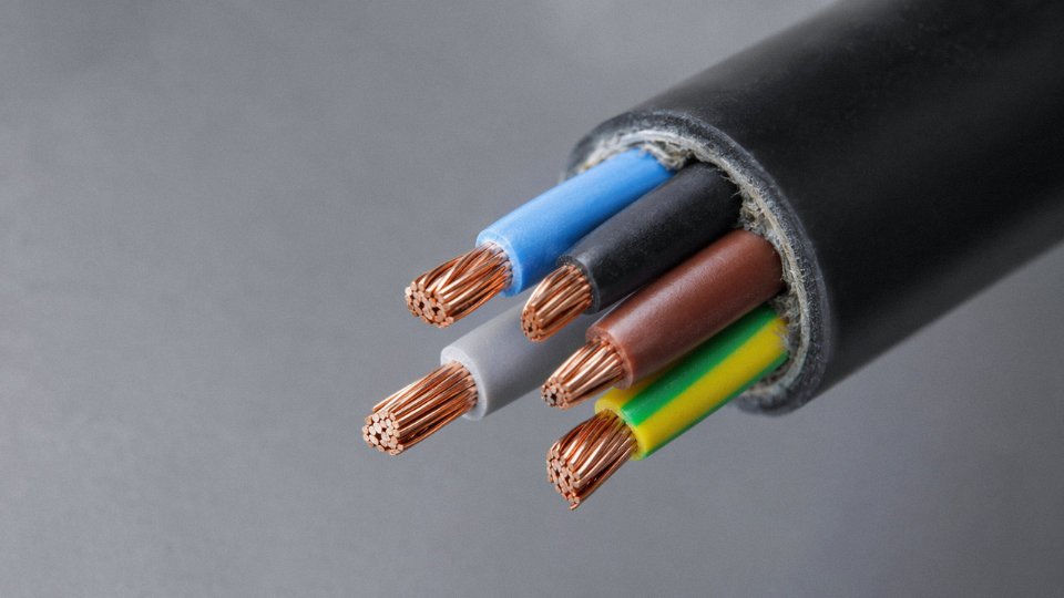
Jinda’s KVV series (PVC insulated and jacketed) covers standard industrial environments. The KYJV series uses XLPE insulation, which is worth the modest price premium in higher-temperature installations or where the control cable runs adjacent to hot equipment. Both series are available with flame-retardant (FR) and fire-resistant (FRS) jacket options — FR limits flame propagation; FRS maintains circuit integrity during a fire, which matters for emergency shutdown and safety circuits.
Instrumentation and Signal Cable Requirements
Analog signals — 4–20 mA loops, thermocouple pairs, RTD circuits, fieldbus — are where cheap cable choices create the most insidious problems. You won’t necessarily see a failure; you’ll see a 4–20 mA signal that wanders by half a milliamp, or a temperature reading that drifts during motor starts, and you’ll spend days chasing a process control problem that’s actually a cabling problem.
Individual shielded twisted pairs (ISTP construction) are the minimum for analog instrumentation near power circuits. An overall shield on top of that provides additional rejection of high-frequency noise. The drain wire from each shield terminates at a single-point ground — not both ends, not floating, not “connected wherever convenient.” PE or XLPE insulation offers lower dielectric constant than PVC, which reduces signal distortion on longer runs.
Connecting shield drain wires at both ends of an instrumentation cable eliminates ground loops and improves noise rejection.False
Grounding both ends of a shield creates a ground loop — any potential difference between the two ground points drives a current through the shield that induces noise directly into the signal conductors. Single-point grounding at the control panel end is the standard practice for analog instrumentation.
Jinda’s DJYPVP series provides individual copper foil shielding per pair plus an overall braided shield — the right construction for 4–20 mA, thermocouple, RTD, and most fieldbus applications running near power circuits.
VFD Cable Requirements
Variable frequency drive output cables are in a category of their own. The steep voltage rise times (dV/dt) from modern IGBT drives — often in the range of 5–10 kV/µs — generate high-frequency ground currents that will find any path back to the drive, including bearing grease films, instrumentation cable shields, and building steel. Standard power cable is not adequate here.
Proper VFD cable uses symmetrical three-phase conductors with three symmetrically placed ground conductors — not a single ground wire offset to one side. That symmetry is what cancels the circulating ground currents. Low-capacitance construction reduces leakage current to ground and bearing current. An overall copper braid shield provides low-impedance high-frequency containment. Jinda’s VFD-rated cable series is built to IEC 60502-1 and is compatible with the installation requirements of major drive manufacturers — which increasingly specify cable type by name in their warranty documentation.
Procurement and Quality Assurance
For international projects, confirm that cables carry third-party certification for the destination market before the order ships. UL listing for North America, CE marking for Europe, CCC for China, KEMA or BASEC where required — these are not interchangeable. Request full test reports: insulation resistance, Hi-Pot (voltage withstand), and conductor resistance per IEC 60228. On large projects, Jinda offers factory inspection appointments, third-party witness testing, and drum-by-drum test certificates as standard project supply documentation.
The total cost calculation is straightforward. A control cable upgrade from standard PVC to shielded FR-XLPE might add 15–40% to the per-meter material cost, depending on core count and shield construction. One EMI-driven process shutdown in a continuous production environment — lost product, maintenance labor, root-cause investigation — typically costs multiples of the entire cable budget for the affected circuit. Specifying correctly the first time is not over-engineering. It’s arithmetic.