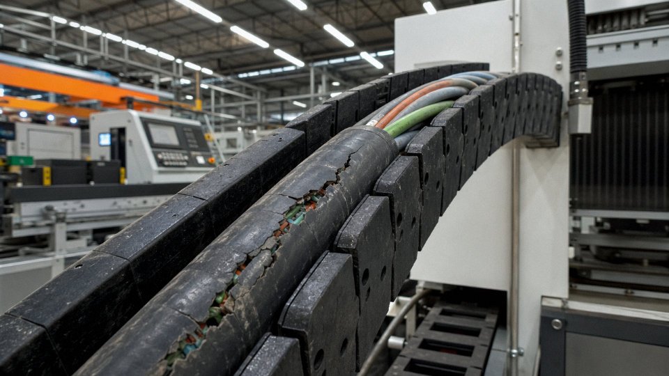
A machine stops mid-cycle. The PLC shows a fault but the drive itself is fine, the power supply reads nominal, and you’ve already swapped the sensor twice. After two hours of chasing ghosts, an electrician finds a cracked jacket on a flexing control cable — one conductor intermittently opening under movement. That’s not a cable failure, that’s a design mismatch: the wrong cable in a flex application. The downtime cost on a high-output line easily runs into thousands of dollars per hour, and the root cause fits in your hand.
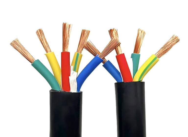
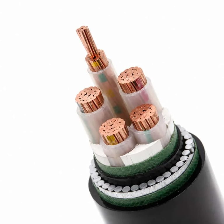
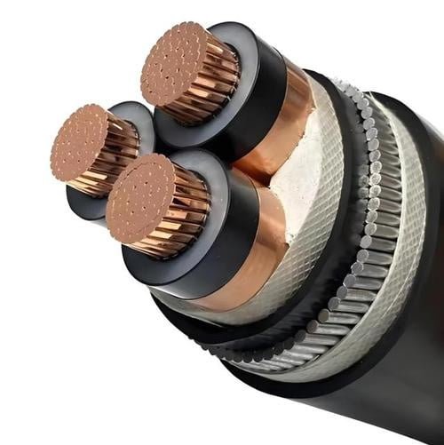
A control cable transmits low-voltage electrical signals and switching commands between control devices — PLCs, sensors, relays, and actuators — rather than delivering bulk power. Conductor cross-sections typically run 0.5 mm² to 10 mm², rated at 300/500 V or 450/750 V. Construction layers — conductor, insulation, screening, sheath — are each engineered to protect signal integrity under the mechanical and electrical conditions of industrial environments.
What makes control cables genuinely interesting, from an engineering standpoint, is that every layer in the construction is doing a specific job — and when you understand what each one is actually resisting (EMI, flex fatigue, chemical ingress, capacitive crosstalk), cable selection stops being a purchasing formality and starts looking more like a short materials-engineering problem. The rest of this article works through that layer by layer.
Conductor Design: How Electrons Actually Move Through a Control Cable
The conductor is where everything starts. Get it wrong and you’re chasing ghost faults — intermittent relay chatter, PLC input cards that read erratically, solenoids that cycle slowly because the control voltage has dropped below threshold. None of that shows up obviously on a multimeter at the panel end. You have to understand what’s happening inside the wire itself.
Copper Purity and Why It’s Not Optional
Virtually all industrial control cable conductors are electrolytic-grade copper, minimum 99.9% purity, and that standard exists for a real reason. The resistivity of high-purity copper sits at roughly 1.72 × 10⁻⁸ Ω·m. Drop below that purity threshold — through recycled or lower-grade copper, which does appear in cheaper cable from less scrupulous suppliers — and resistivity climbs, resistance per meter rises, and in a 24 VDC control loop running 50 or 80 meters of cable, you can lose enough voltage to push a relay into its dropout zone under load.
Tinned copper is the right choice for marine installations, chemical plants, food processing environments, anywhere condensation is a seasonal or daily reality. The tin coating prevents surface oxidation. Without it, copper oxide builds up at terminations and under ferrules, raising contact resistance over months or years — not dramatically, just enough to cause problems that are genuinely hard to diagnose in winter on a wet production floor.
Electrolytic-grade copper conductors must achieve a minimum purity of 99.9% to meet the resistivity specification underpinning IEC 60228 resistance limits.True
IEC 60228 specifies maximum DC resistance per unit length for each conductor class and cross-section. Meeting those limits requires copper of at least 99.9% purity, as lower-purity alloys have higher resistivity that pushes resistance per meter over the allowed ceiling.
Stranding Class: The Decision That Determines Service Life
IEC 60228 defines conductor classes, and the choice between them is a practical engineering decision, not just a catalog detail.
Class 1 is solid wire. Fine for fixed installations in conduit where nothing moves — it’s cheaper, holds a terminal connection cleanly, and won’t loosen easily under vibration-free conditions. But put it in a cable tray that sees even modest vibration from nearby machinery, and work-hardening cracks the conductor at bending points over months. I’ve seen 2.5 mm² solid conductors in MCC trunkings that looked fine externally but had fractured internally at the tray support edges after three or four years.
Class 2 is standard stranded — the workhouse of most panel wiring and fixed multi-core runs. More flexible than Class 1, tolerates occasional reconfiguration.
Class 5 is fine-wire stranded, and it’s what you want for anything that moves or flexes in service. A 1.5 mm² Class 5 conductor typically consists of around 30 wires of approximately 0.25 mm diameter each. That geometry distributes bending stress across dozens of individual filaments. Each individual wire deflects a tiny amount; none sees enough cyclic strain to fatigue. A solid 1.5 mm² conductor in the same application would crack within a few hundred flex cycles. For drag chains, robotic arm connections, or any cable that moves with the machine, Class 5 isn’t a premium upgrade — it’s the correct specification.
Cross-Section Selection by Circuit Type
The 0.5 mm² to 10 mm² range in control cables isn’t arbitrary. In practice, most of the work is done by four or five sizes:
| Circuit Type | Typical Cross-Section | Governing Constraint |
|---|---|---|
| Indicator lamp, pilot light | 0.5 mm² | Current well under 1 A; length is the real variable |
| PLC digital I/O wiring | 0.75 mm² | IEC and UL both accept this for low-current signal circuits |
| Relay coils, solenoid valves | 1.5 mm² | Inrush and coil-hold current, typically 0.5–2 A depending on device |
| MCC control wiring, motor starters | 2.5–4 mm² | Inrush to auxiliary contactors; 4 mm² where runs exceed 40–50 m |
| High-inrush or longer MCC runs | up to 6–10 mm² | Usually a site-specific voltage drop calculation drives this |
The IEC 60228 resistance ceiling for a 1.5 mm² copper conductor is 13.3 Ω/km at 20 °C. That translates to about 13.3 mΩ per meter. On a 60-meter round-trip circuit (30 m of cable out, 30 m return), you’re looking at roughly 0.8 Ω total conductor resistance. At 100 mA coil current that’s only 80 mV of drop — fine. At 500 mA with a marginal 24 VDC supply sitting at 22 V after rectifier losses, that same resistance matters. Relay coils rated to drop out at 18 V don’t have much margin left, and if the cable has aged and resistance has crept up through oxidized ferrules, you’ll see relay chatter under cold-start inrush conditions.
Undersizing is the more common error in practice, but oversizing creates its own headaches — harder to dress neatly in terminal rails, ferrules that don’t fit the block, and in multi-core cables, unnecessary weight and bend radius increases.
Color Coding: Faster Commissioning, Safer Maintenance
IEC 60446 defines conductor identification by color, and the principle is simple: consistent, unambiguous identification across every core in a multi-core cable reduces both commissioning time and the risk of incorrect terminations during maintenance. In a 12-core or 24-core cable, if cores 9 through 12 are all the same color because the manufacturer cut corners, an electrician tracing faults at 2 AM will eventually make a wiring error. It’s not a hypothetical.
North American practice under NEC and CSA conventions differs — black insulation with numbered sleeves is common in MCC panels, while IEC installations in Europe and much of Asia rely more heavily on the full color sequence. When you’re sourcing cable for a mixed installation, or for export to multiple regions, confirm color coding convention explicitly in the purchase specification. “Per IEC 60446” and “per local practice” are not the same thing, and finding that out during FAT is late.
Insulation and Jacket Materials: How the Cable Protects Its Own Signal Path
The conductor does the electrical work, but the insulation and jacket system is what keeps that work reliable over a 20-year service life in a hostile environment. Get this selection wrong and you’re looking at premature insulation breakdown, nuisance trips from ground faults, or — in the worst case — a fire that the cable itself propagates.
PVC: The Baseline Material and Its Real Limits
Polyvinyl chloride dominates control cable insulation worldwide for straightforward reasons: it’s cheap, self-extinguishing, easy to extrude consistently, and rated to 70°C conductor temperature under IEC 60227. For the vast majority of indoor cable trays, switchgear panels, and sheltered outdoor conduit runs, it does the job without drama.
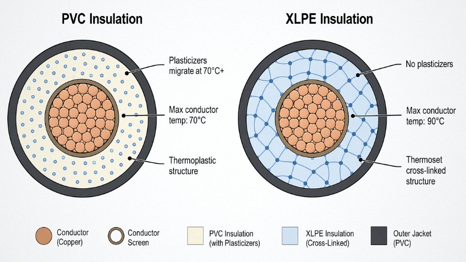
The aging mechanism is plasticizer migration. PVC is a rigid polymer on its own; manufacturers add phthalate or adipate plasticizers to make it flexible. Over time — accelerated by heat — those plasticizers volatilize or leach out, leaving the insulation brittle and prone to cracking under vibration or thermal cycling. In a room-temperature panel room, a quality PVC control cable might last 25–30 years. Run the same cable through a conduit bank above a steam header where ambient regularly hits 55–60°C, and you could be looking at insulation that’s visibly checking and stiff in under a decade. That’s not a hypothetical; any maintenance engineer who’s pulled old PVC cables out of a hot utility tunnel has seen exactly this.
XLPE: When Temperature Ratings Actually Matter
Cross-linked polyethylene solves the plasticizer problem by eliminating plasticizers entirely. The cross-linking process — either peroxide-initiated or electron-beam irradiation — creates covalent bonds between polyethylene chains, converting a thermoplastic into a thermoset structure. The practical result: temperature rating rises to 90°C, the material doesn’t soften and deform under sustained heat load, and dielectric losses drop compared to PVC.
This matters in specific scenarios. Cables routed near induction furnaces, through conduit embedded in sun-exposed concrete in the Middle East (where conduit internal temperatures can spike well above ambient), or in direct-burial runs where soil thermal resistivity is high — these are the applications where PVC’s 70°C limit is genuinely marginal rather than a theoretical concern. XLPE’s higher cost — roughly 15–35% more than equivalent PVC, depending on conductor cross-section and order volume — is usually justified in those conditions.
XLPE insulation eliminates plasticizer migration because it contains no plasticizers and its cross-linked molecular structure is stable at elevated temperatures.True
PVC requires plasticizers for flexibility; XLPE achieves flexibility through its polymer chain structure. Cross-linking prevents the thermal softening and chemical leaching mechanisms that degrade PVC over time in hot environments.
LSZH: The Non-Negotiable Choice for Enclosed Spaces
When PVC burns, it releases hydrogen chloride gas. HCl is corrosive — it will destroy unprotected electronics in a control room within hours of a fire event — and it’s toxic in confined spaces where evacuation is slow or difficult. Tunnels, offshore platform accommodation areas, data centers, and metro rail installations have largely standardized on LSZH (low-smoke zero-halogen) compounds for exactly this reason.
LSZH insulation uses mineral-filled polyolefin blends, typically with aluminum trihydrate or magnesium hydroxide as flame retardants. These release water vapor when heated, absorbing energy and diluting combustion gases. The tradeoff: LSZH compounds are generally less flexible than PVC in cold temperatures, and some formulations are harder to terminate cleanly because they don’t strip as predictably. Worth knowing before you spec them for a cold-climate outdoor installation without checking the low-temperature flexibility rating in the datasheet.
Compliance benchmarks are IEC 60332-3 for flame spread and IEC 61034 for smoke density. Both must be met for the cable to be genuinely LSZH-rated, not just marketed as low-smoke.
Bedding, Armor, and Outer Jacket: The Mechanical Stack
Beyond the insulation, most industrial control cables add two or three more layers, each doing a specific job.
Bedding tape — usually a non-woven polyester or rubber compound — sits between the cabled cores and the armor. It prevents the armor wires from cutting into insulation under load and provides a degree of radial stability. Thin layer, often overlooked, genuinely important.
Armor type drives the bulk of the mechanical selection decision:
| Environment | Typical Armor Type | Reason |
|---|---|---|
| Indoor cable tray, no mechanical risk | Unarmored | Weight and flexibility priority |
| Direct burial, rodent risk | Steel wire armor (SWA) | Crush and gnaw resistance |
| Tray with occasional maintenance traffic | Steel tape armor (STA) | Lighter than SWA, adequate crush resistance |
| Offshore topside, weight-sensitive | Aluminum wire armor (AWA) | Corrosion resistance, ~40% lighter than SWA |
| Chemical plant, acidic splash zones | PVC or PE oversheathed SWA | Armor protected from chemical attack |
| Food processing, wash-down areas | Smooth PVC outer, no crevices | Hygiene, chemical resistance to cleaning agents |
The outer jacket is the last line of defense — typically PVC or polyethylene for general use, with polychloroprene (neoprene) or polyurethane used where abrasion or hydrocarbon exposure is a concern. On offshore installations, you’ll commonly see a red or orange outer sheath for identification; in food plants, white or light grey for visual contamination checks. These aren’t just cosmetic preferences — they’re embedded in the facility safety and housekeeping standards.
One practical warning: don’t assume that because a cable carries a steel wire armor designation it’s automatically suitable for direct burial. The armor protects against mechanical damage; moisture ingress through the cable ends, through improperly sealed joints, or via capillary action through the bedding is a separate failure mode. Moisture barriers and proper gland sealing are the armor’s necessary partners, not optional extras.
Shielding Mechanisms: How Control Cables Reject Electrical Noise
A 24 VDC control signal sounds robust until you do the arithmetic. If the logic threshold sits at 10 V, you only have 14 V of margin — and a nearby variable-frequency drive switching at 8 kHz can induce several volts of noise onto an unshielded cable run in under a meter. That’s not a theoretical edge case. In practice, unshielded control cables routed in the same tray as VFD output conductors cause nuisance trips and ghost inputs on a regular basis. The shield is not an optional upgrade; it’s load-bearing.
Why Control Circuits Are More Vulnerable Than You’d Expect
The noise sources in a modern factory are getting worse, not better. VFDs are the main offender — switching harmonics typically fall in the 2–20 kHz range, and the energy is real enough to saturate short cable runs. Inductive loads switching (contactors, solenoid valves, relay coils without proper snubbers) generate sharp transients with rise times under a microsecond, which translates to broadband high-frequency content. Smart factory environments add radio-frequency emitters — wireless sensors, RFID readers, even poorly suppressed servo drives. Low-level analog signals, 4–20 mA loops especially, are disproportionately affected because the affected signal range is narrow and the receiving circuitry is sensitive.
Three Mechanisms, One Practical Answer
Shielding works through three distinct physical mechanisms, and understanding which one matters for your application prevents bad purchasing decisions.
Electrostatic shielding (the Faraday cage effect) is what most people picture — a conductive layer surrounding the conductor pair intercepts capacitively coupled electric fields before they reach the signal conductors. An aluminum-polyester foil with a drain wire does this at essentially 100% coverage. For analog instrumentation runs in a cable tray that’s well separated from power conductors, this is often enough.
Magnetic shielding — attenuation of H-fields using ferromagnetic materials — is theoretically possible but largely irrelevant for flexible industrial cables. Mu-metal and similar materials are brittle, heavy, and expensive. You won’t find them in standard control cable catalogs for good reason.
The practical answer for magnetic noise rejection is twisted pairs. When a conductor pair is twisted uniformly, each half-twist experiences equal and opposite induced voltages from an external magnetic field. Those voltages cancel differentially at the receiver. Tighter twist lay = better rejection at higher frequencies, which is why instrumentation-grade cables spec their twist lay explicitly. Don’t assume all “twisted pair” cables are equivalent — a sloppy 50 mm lay is not the same as a precision 25 mm lay near a servo cabinet.
Foil, Braid, or Both
Aluminum-polyester (Al/PET) foil shields are lightweight, add minimal diameter, and deliver 100% coverage. Their weakness is mechanical — repeated flexing cracks the foil, which is why you’ll find them in fixed installations and cable trays rather than on robot arms or festoon systems. The drain wire is non-negotiable; it’s your actual electrical connection to the shield.
Tinned copper braid gives you 85–95% coverage depending on braid angle and density, measurably lower DC resistance than foil, and far better flex life. On a cable that moves — drag chains, machine tools, anything cycled thousands of times — braid is the correct choice. The coverage gap is real but usually acceptable for digital I/O; it starts to matter if you’re running high-impedance analog signals near aggressive noise sources.
Combined foil-plus-braid construction addresses both: the foil handles high-frequency capacitive coupling, the braid handles lower-impedance grounding and provides physical protection for the foil. Cable running within two meters of a VFD cabinet deserves this construction. The cost premium over foil-only is typically 15–35% depending on conductor count and braid coverage spec, and it’s almost always worth it in that application.
A braided shield provides 100% electromagnetic coverage equivalent to foil shieldingFalse
Tinned copper braid typically achieves 85–95% optical coverage depending on braid angle and pick count. Foil provides geometric 100% coverage but has higher resistance and poor flex life. Neither is universally superior — the right choice depends on frequency range, flex requirements, and noise environment.
Grounding: Where Most Installations Go Wrong
The shield does nothing floating. But how you ground it matters as much as whether you ground it.
Single-end grounding — connecting the shield drain wire to earth at one end only, usually the control panel end — breaks the capacitive coupling path effectively for most analog signal cables. It’s the right default for 4–20 mA loops and thermocouple circuits. The reason to avoid both-end grounding in those cases is ground loops: if the panel earth and the field device earth are at even slightly different potentials (and in large plants, they often are, by 1–5 V or more), current flows through the shield and induces noise directly onto the signal conductors. Ironic, but real.
Both-end grounding does have a place. At high frequencies — think digital fieldbus, fast digital I/O near VFDs — a single-end ground leaves the shield’s far end floating, which can actually allow it to act as an antenna. Grounding both ends lowers shield impedance across the frequency band where the noise exists. If you go that route, bond both ends to a common low-impedance ground plane and keep ground potential differences below 50 mV. That requires proper plant earthing infrastructure, which is a separate conversation entirely.
Overall Shield Versus Individually Shielded Pairs
A 12-pair control cable with one overall shield is cheaper and smaller in diameter than the same cable with individually shielded pairs (ISP). For a run carrying only digital I/O, the overall shield is probably fine. Run that same cable with four 4–20 mA analog loops and eight digital channels mixed together, and you have a problem.
Inter-pair crosstalk is the mechanism. A fast-switching digital signal on pair 3 capacitively couples into pair 7, which happens to carry your analog pressure transmitter signal. An overall shield protects against external noise but does nothing about internal crosstalk between pairs. ISP construction gives each pair its own foil shield, isolating pairs from each other. For mixed analog/digital cables, ISP is not optional — it’s the difference between a stable 4–20 mA reading and a loop that drifts ±0.3 mA every time a nearby output switches. Most experienced panel builders know this, but procurement teams buying cable on price alone frequently miss it.
Multi-Core Layouts and Pair Counting: How Cable Architecture Matches System Complexity
The number of cores in a control cable isn’t arbitrary — it’s a direct reflection of the control topology it feeds. Get it wrong and you’re either pulling a second cable through a conduit that barely had room for the first, or you’re running a 37-core trunk when a 12-core would have done the job with change to spare.
Core Count as a Mirror of System Complexity
At the simple end: a two-core cable handles a single two-wire sensor circuit, a dry contact, or an on/off solenoid. Clean, easy, nothing to overthink. Four-core opens the door to redundant two-wire circuits — common in safety-instrumented systems where you need a primary and backup signal path in the same run but still want physical separation within the jacket rather than pulling two separate cables.
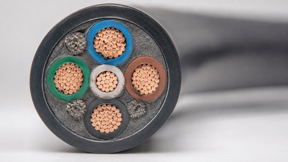
Seven-core and twelve-core cables are the workhorses for junction box home-runs in field instrumentation. A typical P&ID node with four or five 4–20 mA loops, a thermocouple input, and a discrete alarm output lands squarely in the 7–12 core range. Installers and commissioning engineers know this range well; it’s where most of the real wiring work happens.
Above that, 19-core through 61-core cables are marshalling trunk cables — the ones that run from a remote I/O panel or marshalling cabinet back to a DCS or PLC rack room, sometimes covering 200–400 meters in a large petrochemical plant or offshore topsides installation. These are heavy, stiff, and expensive per meter, so over-specifying the core count matters more than it does on a short field run.
Pair, Triple, and Quad Logic
Twisted pairs exist for a reason. Differential signaling — where the receiver reads the voltage difference between two conductors rather than a single conductor referenced to ground — rejects common-mode noise by design. The twist rate (typically 12–25 mm lay length for instrumentation pairs) means any induced electromagnetic interference hits both conductors in nearly equal measure and cancels at the receiver. Cut corners on lay length consistency across a drum and you degrade the balance; that shows up as elevated common-mode rejection failure in high-noise environments like variable-frequency drive installations.
Triads serve a different purpose. PT100 resistance temperature detectors genuinely require a three-wire connection to compensate for lead resistance — run them on a two-core pair and your temperature reading drifts with cable temperature, which is embarrassing in a food processing plant where a 2°C error matters. Three-phase motor feedback encoders similarly need triad groupings. Quads — four conductors in a group — appear in pilot wire protection schemes in substation control cabling and in some teleprotection circuits; the geometry allows both a current loop and a metallic return path within the same twisted unit.
Core Identification: Color, Number, or Both
Up to about 12 cores, color coding per IEC 60446 or DIN VDE 0293 usually suffices. Standard sequences (brown, black, grey for the first triad, then repeating with a tracer stripe) give technicians a fast visual reference during termination. Above 12 cores, colors inevitably repeat, and the only reliable system is sequential numbering printed or embossed directly on the insulation — typically in white ink on dark insulation or vice versa. Most practical cables above 19 cores use both: a base color sequence for the first rotation, then numbers from core 1 through N. A commissioning engineer working in a dim marshalling cabinet at 2 AM will thank whoever specified the numbered option.
Uniform vs. Mixed Cross-Section Designs
Standard multi-core cables like a 12×1.5 mm² suit homogeneous I/O loops perfectly well. But offshore topsides projects frequently benefit from mixed cross-section designs — for example, 4×2.5 mm² conductors for solenoid power feeds combined with 8×0.75 mm² instrumentation cores in a single overall jacket. This reduces conduit fill, cuts installation labor, and simplifies cable tray management in platforms where tray space is genuinely constrained. The trade-off is that mixed cables require more careful procurement specification and tighter production control; if the 2.5 mm² conductors aren’t properly separated from the 0.75 mm² signal cores during cabling, crosstalk and mechanical stress concentrations become real problems.
Jinda's five manufacturing bases operate dedicated extrusion and cabling lines that maintain consistent lay length control across full drum lengths for multi-core counts from 2 to 61 cores.True
Consistent lay length throughout a complete cable drum is a production discipline requirement, not just a design spec — variation along the drum length degrades the electrical balance of twisted pairs and can cause differential signal errors in sensitive instrumentation loops. Dedicated cabling lines with controlled take-up tension and lay pitch monitoring are what make this achievable at scale.
How Control Cables Perform Under Real Operating Stresses: Temperature, Flex, and Chemical Exposure
A cable that passes every datasheet specification can still fail prematurely if it was selected against lab conditions rather than the actual stresses on your plant floor. This is where materials chemistry and mechanical engineering stop being abstract and start costing you downtime.
Temperature Cycling in High-Heat Environments
The problem with PVC insulation in steelworks and foundries isn’t steady-state heat — it’s the cycling. Copper has a coefficient of thermal expansion around 17 × 10⁻⁶ /°C. PVC sits somewhere between 80 and 100 × 10⁻⁶ /°C depending on plasticizer loading. That’s a roughly five-to-six-fold mismatch. Every time a cable near a furnace tap heats up and cools back down, the insulation expands and contracts far more than the conductor beneath it. Over hundreds of cycles — which happens within a single year in most melt-shop environments — the interface develops micro-cracks. You won’t see them on a visual inspection. You’ll see them as an insulation resistance reading that keeps drifting downward until you get nuisance trips or worse, a ground fault that takes out a whole control loop.
XLPE handles this far better. The cross-linked thermoset network constrains molecular movement; the effective CTE is tighter, and the material doesn’t soften and flow the way thermoplastic PVC does above roughly 70–75°C. If you’re routing control cables anywhere within a few meters of ladles, induction furnaces, or reheat furnace zones, XLPE insulation is worth the cost premium — which in practice runs 15–30% higher per meter depending on conductor count and cross-section.
Flex Life in Cable Carriers and Robotic Cells
Robotic welding cells and gantry crane cable track systems are brutal environments for cables. A typical automotive body-shop robot running two shifts will accumulate somewhere between 5 and 10 million flex cycles over its service life, and the cable has to survive every one of them without conductor fracture or jacket cracking.
Standard Class 2 or Class 5 stranded conductors simply aren’t built for this. You need Class 6 fine-wire construction — individual wire diameters at or below 0.1 mm — which distributes the bending stress across a much larger number of smaller wires. But conductor design is only part of it. The bedding layer between the cores and the outer jacket needs to be soft and low-compression, otherwise the cores bind against each other during flex and work-harden locally. Jacket compound matters too: elongation at break needs to be above 300%, and in my experience 350–400% is a more comfortable target for high-cycle applications. Some PUR-jacketed flex cables spec out above 450%. Skimp on any one of these three elements and you’ll be pulling a new cable through the drag chain in 18 months instead of running the full equipment lifecycle.
Oil, Coolant, and Chemical Exposure
Standard PVC with conventional plasticizer systems will swell visibly in mineral oil within a matter of weeks. The plasticizers leach out, the jacket softens, and the dimensional stability of the cable deteriorates — which eventually compromises the insulation underneath. In CNC machining centers where coolant and cutting oil are essentially part of the atmosphere, or on offshore drilling rigs where hydraulic fluid contamination is constant, this isn’t a theoretical concern. It’s a routine failure mode.
CPE (chlorinated polyethylene) and PUR jackets are the practical answers here. CPE offers solid resistance to oil, fuel, and many hydraulic fluids at a moderate cost premium over PVC. PUR goes further — it resists abrasion exceptionally well on top of chemical resistance, which makes it the default choice for machine tool environments where cables drag across chip conveyors or sit in coolant sumps. Neither material is universally better; PUR costs more and can be harder to strip cleanly in the field.
PVC-jacketed control cables are adequate for long-term use in mineral oil environmentsFalse
Standard plasticized PVC absorbs mineral oil, causing plasticizer extraction, jacket swelling, and progressive insulation degradation. CPE or PUR jackets are required for sustained oil-contact applications.
UV, Ozone, and Outdoor Durability
Outdoor cable runs — whether along pipeline rights-of-way, in solar farm cable trays, or on port infrastructure — expose PVC to a combination of UV radiation and atmospheric ozone that standard formulations simply aren’t stabilized against. Typical unprotected PVC will show surface chalking and micro-cracking within two to three years outdoors in mid-latitude climates; in high-UV environments like the Middle East or Australia, degradation starts faster.
Carbon-black stabilized polyethylene and properly UV-stabilized PVC compounds are a different story. The carbon black acts as a UV absorber and free-radical scavenger. Well-formulated outdoor-grade compounds can maintain insulation resistance above 100 MΩ·km across a 20–25 year outdoor service life — though that upper bound depends heavily on installation practice, whether the cable sees standing water, and whether it’s in conduit or direct-exposed.
Mechanical Protection: Armor Ratings and Crush Resistance
Cable trays in underground ducts, tunnels, and busy industrial cable routes need mechanical protection that insulation alone can’t provide. Steel wire armor (SWA) under IEC 60502-1 is rated to handle lateral crush forces in the range of 4 kN per the standard test — enough to survive incidental mechanical traffic from maintenance foot loads and equipment in shared cable routes. Flat steel tape armor offers similar crush resistance and is sometimes easier to pull through conduit, though it’s less effective in applications requiring tensile protection.
The table below gives a practical comparison across common armor types.
| Armor Type | Crush Resistance (approx.) | Tensile Load Capability | Best Fit Application |
|---|---|---|---|
| Steel wire armor (SWA) | ~4 kN lateral (IEC 60502-1) | High | Underground ducts, tray with mechanical risk |
| Flat steel tape armor | ~3.5–4 kN lateral | Moderate | Fixed conduit runs, tunnels |
| Aluminum wire armor (AWA) | ~2.5–3 kN lateral | Moderate | Weight-sensitive applications, some marine |
| Braided steel over-braid | Variable, typically lower | Low–moderate | Flexible installations needing moderate protection |
Values vary with armor wire diameter and lay; always verify against the specific manufacturer’s test data for the cable construction you’re specifying.
An operational note: armor provides mechanical protection, not EMI shielding. A common procurement error is assuming SWA substitutes for a copper braid shield in noisy environments. It doesn’t. If your application needs both, specify both.
Testing and Quality Verification: How You Confirm a Control Cable Will Work Before Installation
Receiving a cable reel on site and assuming it meets spec is a gamble. It happens constantly — procurement pressure, tight schedules, a supplier you haven’t used before. The tests below are how you stop guessing and start knowing.
Conductor Resistance per IEC 60228
This is the first thing to check, and it catches more problems than most engineers expect. Measure DC resistance at 20°C (or correct to 20°C if your lab is warmer) and compare against the class maximum in IEC 60228. For a 1.5 mm² conductor, the limit is 13.3 Ω/km. Exceed that and the conductor cross-section is almost certainly underweight — meaning the manufacturer drew the wire thinner than declared, saving copper at your expense.
A 1.5 mm² conductor measuring above 13.3 Ω/km per IEC 60228 indicates insufficient copper cross-section and non-compliant construction.True
IEC 60228 Table 1 sets a maximum DC resistance of 13.3 Ω/km at 20°C for Class 1 and Class 2 conductors at 1.5 mm². Exceeding this value directly indicates the conductor has less copper than specified, which increases voltage drop and heat generation in service.
Underweight conductors show up more often in lower-cost product from non-audited sources than most buyers realize. The consequence in service isn’t always dramatic — it’s a slow burn: higher voltage drop on 24 V DC control loops, nuisance trips, relay coils running warm. Not a failure you can trace easily.
High-Voltage Withstand (HV) Test
Apply 2000 V AC or 3000 V DC between conductors and screen for one full minute per IEC 60502. No breakdown, no flashover. This is a go/no-go test — the cable either holds or it doesn’t. Any puncture during this test means the insulation has a weak spot: a void, a contaminant particle, a thin-wall section from poor extrusion control. Installing that cable means the fault is sitting in your conduit waiting for a transient spike to find it.
Insulation Resistance
Use a 500 V or 1000 V DC megohmmeter. IEC 60502 requires a minimum of 1000 MΩ·km at 20°C for PVC-insulated cables. Values well below that threshold — say, 50–200 MΩ·km on a new drum — usually mean one of three things: moisture ingress through a jacket defect, insulation compound with excessive plasticizer or filler substitution, or a cable that’s been stored badly. In practice, a good factory-fresh PVC control cable should read several thousand MΩ·km, not barely scraping the minimum. If it’s just over 1000, ask questions.
Capacitance and Inductance for Shielded Pairs
For shielded twisted pairs carrying fast digital I/O or instrumentation signals, mutual capacitance between conductors should stay within roughly ±10% of the design value, measured per IEC 60885-1. Capacitance imbalance affects signal timing and common-mode rejection. This matters less for a simple on/off dry contact and a great deal more for anything running at higher data rates across long cable runs. Check this spec when you’re buying for a PLC remote I/O network or a distributed control system — it’s often omitted from basic datasheets and worth requesting explicitly.
Flame Propagation and Fire Performance
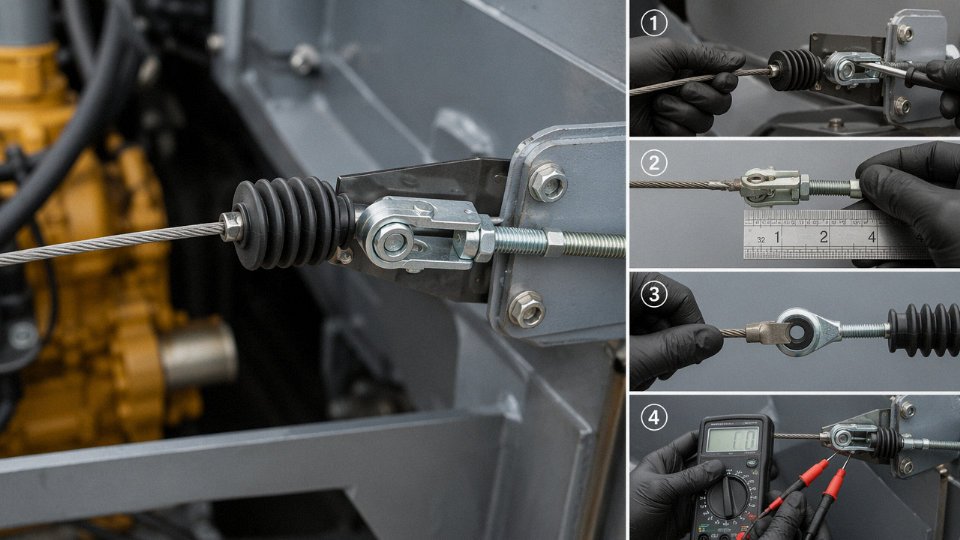
IEC 60332-1 covers single-cable vertical flame — the cable must self-extinguish within 60 seconds after the burner is removed. For bundled installations (cable trays with multiple cables grouped together), IEC 60332-3 applies, and it’s significantly more demanding because the thermal mass of multiple cables changes burn behavior substantially.
For LSZH-jacketed cables, two additional tests matter: IEC 61034 for smoke density and IEC 60754 for HCl emission. A cable labeled “LSZH” without test reports for both is just a label. Smoke density below a minimum transmittance level and HCl content below 0.5% by weight are the thresholds that actually define low-smoke, halogen-free performance — not the compound trade name.
Third-Party Certification and Factory Audit Support
Certificates from SGS, TÜV, Bureau Veritas, or national bodies like CCC and UL Listing are documented evidence that an independent party tested production samples against the standard. They’re not a substitute for incoming inspection, but they shift the baseline risk substantially. The certificate number should be verifiable on the issuing body’s website — if it isn’t, treat it as paper.
For major projects, factory audit access matters as much as the certificate itself. Jinda supports customer and third-party factory inspections and provides full test reports traceable to specific production batches, which is the documentation level that project engineers and EPC contractors typically need to close out material submittals.
Installation Practices That Determine Whether a Control Cable Works as Designed
Good cable, badly installed, fails. That sounds obvious, but a significant share of the intermittent faults I’ve seen diagnosed as “PLC noise issues” or “faulty sensors” trace back to installation decisions made during commissioning — often under deadline pressure, by contractors who installed power cables all their lives and treat control cable as just thinner wire.
Separation from Power Cables
Route control cables in their own dedicated trays, physically separated from power runs by at least 200 mm — this is the IEC 61918 recommendation for industrial network environments, and it’s a reasonable floor for general control wiring too. Where tray separation isn’t practical, a grounded metallic barrier between the trays achieves the same result.
The reason isn’t abstract. A 480 V three-phase feeder running parallel to an unshielded control cable for even a few meters can inductively and capacitively couple noise voltages into that control circuit. At 24 VDC logic levels, induced spikes of 5–10 V are enough to cause spurious digital inputs, and in analog 4–20 mA loops, even 1–2 V of noise translates directly into measurement error. Crossings are acceptable — run them perpendicular, not parallel, and the coupling length drops to near zero.
Minimum Bend Radius
Most control cables are rated for a minimum installation bend radius of 6–10× the overall cable diameter. Flex cables used in cable tracks or robotic applications typically need 15× OD or more during continuous motion — check the manufacturer’s data sheet, because the number varies with jacket material, conductor stranding class, and whether the cable has a steel braid.
Violating this during pulling is the insidious failure mode. The cable looks fine at commissioning. Four to six weeks later, intermittent conductor breaks start producing faults that are nearly impossible to locate with standard continuity tests, because the strand fractures only make and break contact under temperature cycling or vibration. Insulation cracking at tight bends takes longer to show up but eventually causes phase-to-ground faults inside conduit where you can’t see them.
Shield Termination Discipline
A shielded cable grounded poorly is sometimes worse than no shield at all — it can act as an antenna rather than a barrier. The rule is 360° shield contact at the termination point, achieved with a proper cable gland that incorporates an integral shield clamp, or a dedicated EMC termination bar with metallic saddle clamps. Pigtail terminations — where the shield braid is twisted into a wire tail and landed on a terminal — should be kept under 50 mm. Beyond that length, the pigtail itself picks up high-frequency interference and defeats the shield’s purpose entirely.
A shield pigtail longer than 50 mm significantly degrades high-frequency noise rejection in control cable installations.True
At frequencies above roughly 1 MHz, a 50+ mm unshielded conductor tail has enough inductance to re-radiate or pick up interference, undermining the shield's attenuation. IEC and EMC engineering references consistently recommend 360° shield termination with the shortest possible connection to ground.
Ground the shield at one end only for analog signal cables to avoid ground loop currents. For cables in noisy environments or longer runs, grounding at both ends with a low-impedance reference plane is sometimes necessary — but that’s a system design decision, not something to sort out on the cable tray.
Conduit Fill and Heat Management
NEC Table 1 (Chapter 9) and equivalent IEC guidance cap conduit fill at roughly 40% of internal cross-sectional area when running three or more conductors. This isn’t bureaucratic conservatism. Packed conduit traps heat, and elevated temperature accelerates insulation aging at a rate that roughly doubles for every 10 °C rise above the cable’s rated operating temperature. A conduit that’s 70% full might run 15–20 °C hotter than one at 40% fill, depending on load and ambient. That difference can cut insulation service life by half or more.
Drum Handling and Storage
Unreeling cable off the end of a stationary drum — pulling the end out axially rather than rolling the drum forward — introduces one twist per meter. On a twisted-pair control cable, that permanently disrupts the lay geometry, degrading the pair’s noise rejection and, on longer runs, increasing capacitive imbalance. It also stresses the jacket. Roll the drum forward on a proper unreeling stand.
Store drums upright on their flanges, not lying flat. A drum stored flat develops flange distortion and oval deformation in the wound layers over months — particularly in warm warehouses. Seal cut ends with tape or heat-shrink end caps immediately after cutting. Moisture wicking into the conductor bundle over weeks of open storage causes corrosion at terminals and can degrade insulation resistance enough to fail a megger test before the cable is even installed.
Frequently Asked Questions About Control Cable Operation and Selection
What is the difference between a control cable and a power cable?
The short answer: purpose, construction priority, and the nature of the signal being carried.
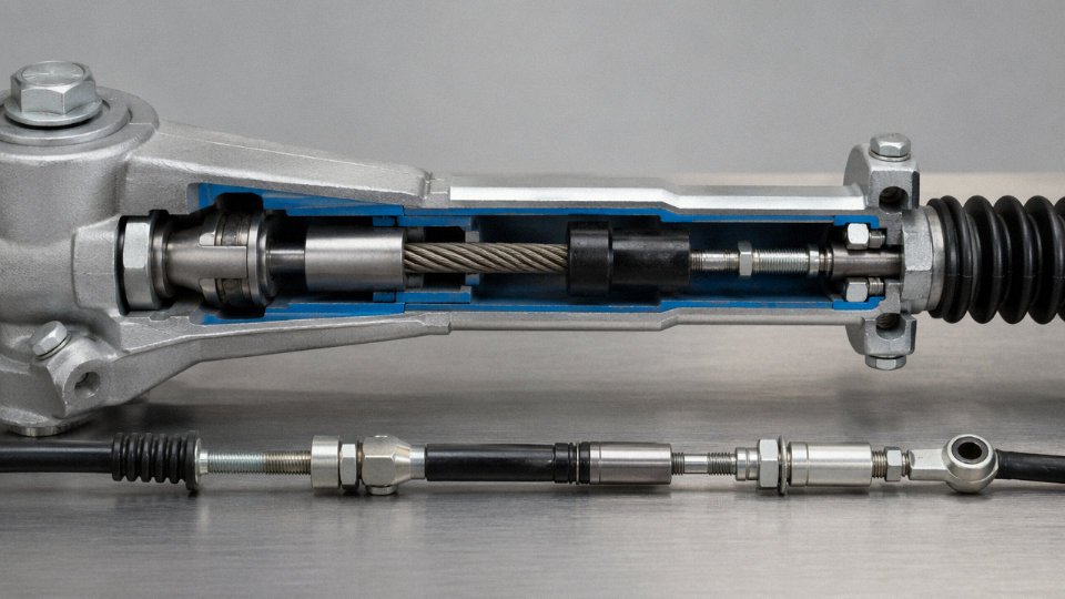
Power cables move bulk energy — think medium-voltage feeders at 6 kV to 35 kV, or low-voltage mains at 400 V carrying 50 A or more to a motor starter. Every design decision in a power cable points toward ampacity, voltage clearance, and dielectric strength. Control cables operate well under 750 V and typically carry switching signals, command loops, or interlock circuits where current rarely exceeds 3–5 A. The engineering priorities flip completely: instead of maximizing conductor cross-section, you optimize multi-core identification, noise immunity, flexibility, and — in many plants — the ability to run dozens of circuits in a single conduit without cross-interference. Physically, a power cable has few cores with large conductors; a control cable has many cores with small conductors, usually 0.5 mm² to 2.5 mm², each individually color-coded or numbered. Mixing the two up during procurement is a surprisingly common error on fast-moving projects, and it tends to surface only after the cable tray is already full.
Can I use a control cable for a 4–20 mA analog signal loop?
Yes, with a condition. The cable must be individually shielded — a single overall braid or foil across a multi-core cable is not adequate for analog signal integrity — and the shield must be grounded at one end only, at the receiver end. Grounding both ends creates a ground loop that injects exactly the kind of low-frequency noise that corrupts a 4–20 mA reading.
For routine process control loops (a temperature transmitter feeding a DCS input card, say), a shielded control cable with good insulation resistance performs acceptably. Where you run into trouble is high-accuracy instrumentation: flow computers, custody transfer meters, precision weighing systems. In those cases, a dedicated instrument cable specified to tighter capacitance balance requirements — per IEC 60544 or ISA-S5.1 guidance — is the right call. The capacitance difference between a standard control cable and a proper instrument cable can matter when your loop has significant cable length, typically above 300–400 m depending on transmitter output impedance.
A shielded control cable grounded at the receiver end only can serve adequately for most standard 4–20 mA process loopsTrue
Single-end shield grounding eliminates ground loops that introduce 50/60 Hz common-mode noise; this is consistent with IEC and ISA wiring practice for instrumentation circuits in industrial environments
How many cores does a typical control cable have?
Standard multi-core counts are 2, 4, 7, 12, 19, 27, 37, and 61 cores, though 2-, 4-, and 7-core designs cover probably 60–70% of what actually gets installed on a typical machine. A small PLC cabinet feeding a conveyor section might use a 7-core or 12-core cable for the entire local I/O run. Large DCS projects are a different story — marshalling cables between field junction boxes and the control room often run 24-pair or 37-pair designs, and a single cable tray segment can carry eight or ten of these in parallel. Getting the pair count wrong at the cable schedule stage usually means a change order, so it pays to add a 15–20% spare core margin at design.
What does XLPE insulation offer over standard PVC in a hot environment?
PVC insulation has a continuous conductor temperature limit of around 70°C. Cross-linked polyethylene (XLPE) raises that to 90°C, and unlike PVC, it does not depend on plasticizer compounds that gradually volatilize or migrate over time. In enclosed cable trays, engine rooms, or anywhere ambient temperature consistently exceeds 40°C, PVC cables are slowly degrading in ways that don’t show up on a megohmmeter until the insulation is already brittle. XLPE also maintains higher insulation resistance across the full service life, which matters for any application where you are running regular IR checks as part of a preventive maintenance program.
The trade-off is cost — XLPE control cables typically run 15–30% higher in unit price than equivalent PVC designs, depending on conductor cross-section and core count. Usually worth it for fixed installations in hot environments; less compelling for a temperate-climate office building.
How do I test whether a control cable shield is working?
Start with a low-resistance ohmmeter across the shield conductors, end to end. For a typical site run of 100–200 m, shield resistance should come in under 5 Ω; higher values suggest a damaged drain wire or a bad termination. Then use a 500 V megohmmeter to check shield-to-core insulation — anything below 100 MΩ is a red flag and warrants investigation before energizing.
During live commissioning, the most direct check is an oscilloscope on a 24 VDC control loop with the machine running. If you see noise spikes above roughly 1 V peak-to-peak, the problem is almost always either an improperly grounded shield (double-grounded, or floating entirely), inadequate physical separation from power cables, or a shield with a mechanical break somewhere along the run. In practice, a significant share of noise complaints on newly commissioned systems trace back to a technician who grounded both shield ends “just to be safe.”
What certifications should I require for an export project?
It depends entirely on where the cable is going, which sounds obvious but is frequently overlooked until a customs hold or a third-party inspection flags the gap.
| Destination | Required Certification |
|---|---|
| European Union | CE marking, CPR (Construction Products Regulation) for fixed installations |
| North America | UL listing or CSA certification (UL 508, CSA C22.2 No. 96) |
| Australia / New Zealand | AS/NZS compliance |
| Russia / CIS countries | GOST-R |
| Hazardous areas (global) | IECEx or ATEX, depending on jurisdiction |
Always request the original test report — not just a certificate copy — and verify the certificate number against the issuing body’s public database before the cable ships. It is not unheard of for documentation to be fabricated or for a certificate to belong to a different product than what was actually manufactured. A five-minute database check before order placement is far less painful than a compliance rejection on-site.