
Misidentifying wire voltage class is one of those errors that usually looks like a minor shortcut right up until it isn’t — a maintenance tech probes the wrong conductor, a procurement team spec’s the wrong insulation grade, or a panel builder routes a circuit through a cable rated for control signals rather than power. The downstream effects range from nuisance tripping to insulation breakdown, arc flash, and failed inspections that push a commissioning date back by weeks. Getting this classification right early, whether you’re sourcing cable, troubleshooting a live panel, or inheriting someone else’s unlabeled installation, is genuinely foundational work.
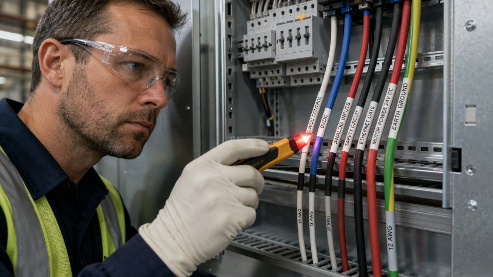
A wire is considered low voltage when it operates in an AC system up to 1,000 V or a DC system up to 1,500 V, per IEC 60038. You can identify low-voltage wiring by checking insulation thickness (typically 0.6–1.2 mm for 1.5–16 mm² conductors), reading cable markings and color codes, or using a non-contact voltage tester, which detects AC fields from as low as 12 V without direct conductor contact.
What makes this trickier in practice is that low voltage is not a single, obvious thing. The category spans a surprisingly wide range — a 24 V control loop and a 400 V three-phase motor feed are both technically low voltage, yet they demand very different handling, termination hardware, and safety precautions. Understanding what actually distinguishes a low-voltage wire, physically and electrically, is what separates a confident identification from an expensive guess.
Understanding the Voltage Classification System: Where Low Voltage Begins and Ends
Before any identification method makes sense, you need a working mental model of how the electrical industry actually carves up the voltage spectrum — because “low voltage” is not just a casual label. It has legally binding definitions that directly govern how wire is built, insulated, and marked.
The Three Tiers That Matter in the Field
IEC 60038, the international standard most of the world’s cable specifications trace back to, draws the lines this way: Extra Low Voltage (ELV) covers AC systems below 50 V and DC systems below 120 V. Low Voltage (LV) spans from those thresholds up to 1,000 V AC or 1,500 V DC. Anything above 1,000 V AC is Medium Voltage or High Voltage territory — a completely different class of equipment, construction, and hazard.
NEC Article 100, which governs North American installations, uses slightly different language but lands in nearly the same place. It defines “600-volt class” as the traditional LV ceiling for most building wiring, though the 2020 NEC cycle has been incrementally aligning with the IEC 1,000 V boundary as solar and EV infrastructure push system voltages higher.
Why does this matter when you’re standing in front of a cable tray trying to figure out what you’re looking at? Because the classification tier is literally baked into the physical wire in front of you.
How Voltage Class Shapes the Wire You’re Holding
Insulation material selection isn’t arbitrary. PVC (polyvinyl chloride) is the workhorse material for standard LV cables — economical, flexible enough for most installation conditions, and rated typically to 70°C continuous conductor temperature. XLPE (cross-linked polyethylene) handles higher thermal loads, usually rated to 90°C, and is the default choice for heavier industrial LV feeders and cables that need better resistance to moisture or chemical exposure. EPR (ethylene propylene rubber) shows up in mining cables and marine applications where flexibility at low temperatures or resistance to ozone matters more than cost.
Insulation wall thickness tracks directly with voltage rating. For conductors in the 1.5 mm² to 16 mm² range — the bread-and-butter sizes for branch circuits and control wiring — typical insulation thickness runs roughly 0.6 mm to 1.2 mm. Push into MV cable (think 6 kV or 10 kV systems) and that wall jumps to 3 mm or more, sometimes considerably more depending on the voltage and standard. That’s a visible, physical difference a trained eye catches immediately.
Real Applications Anchored to Real Numbers
Abstract thresholds become concrete fast when you map them to installations you’ve actually seen:
| Voltage Range | IEC Classification | Typical Application | Typical Insulation Wall (1.5–16 mm²) |
|---|---|---|---|
| 12–50 V AC | ELV | Outdoor landscape lighting, LED drivers | 0.5–0.7 mm |
| 24 V DC | ELV | Industrial PLC/control wiring, sensors | 0.5–0.7 mm |
| 120/240 V AC | LV | Residential branch circuits (North America) | 0.6–1.0 mm |
| 208/480 V AC | LV | Commercial three-phase distribution | 0.8–1.2 mm |
| Up to 1,000 V AC | LV (upper boundary) | Industrial feeders, renewable energy strings | 1.0–1.2 mm |
Thickness ranges depend on conductor cross-section, applicable standard (IEC 60227, IEC 60502, UL 83, etc.), and insulation material. These are field-reference estimates, not design values.
What “0.6/1 kV” on a Cable Drum Label Actually Means
Jinda’s standard LV cable lines are rated to 0.6/1 kV — the most common rating on the global market. That notation means the cable’s insulation is designed to withstand 0.6 kV between any conductor and earth, and 1 kV between any two conductors. It is not a casual marketing figure; it’s the rated voltage the cable is qualified to operate at continuously under IEC 60502-1. When you see “0.6/1 kV” printed on a drum or extruded into a cable jacket, you’re looking at a confirmed low-voltage product that sits well within the IEC LV ceiling.
IEC 60038 defines the upper limit of low voltage as 1,000 V AC and 1,500 V DCTrue
IEC 60038:2009+AMD1:2012 Table 1 explicitly lists these thresholds as the boundaries of the low-voltage classification, and this definition is referenced in IEC 60502-1 for rated cable voltages.
One practical note: ELV systems (your 12 V landscape lighting, your 24 V DC control cabinet) are often overlooked in voltage identification discussions because they feel “safe.” They mostly are, from an electrocution standpoint — but the wiring still fails, still causes fires when undersized, and still needs to be identified correctly before you splice into it.
Reading Cable Markings, Print Lines, and Color Codes: The Fastest Non-Tool Method
Before you reach for a meter, the cable itself is usually trying to tell you what it is. Most modern cables carry enough printed information to confirm voltage class, conductor size, insulation type, and the standard governing their construction — all without touching a single instrument. The catch is knowing how to read it.
What a Standard Cable Print Line Actually Contains
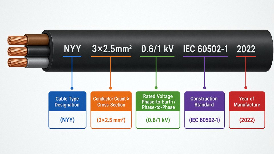
On any IEC-compliant low-voltage power cable, the jacket print line follows a consistent sequence: manufacturer or brand identifier, cable type designation, conductor configuration and cross-section, rated voltage, applicable standard, and typically the year of manufacture or a meter-mark counter. It runs continuously along the jacket, usually repeating every 500 mm to 1,000 mm depending on the manufacturer and cable diameter.
Take a real example: NYY 3×2.5 mm² 0.6/1 kV IEC 60502-1 2022
Breaking that down — NYY is the German-origin designation for a PVC-insulated, PVC-sheathed power cable (widely adopted across Europe, the Middle East, and parts of Asia). 3×2.5 mm² means three conductors, each 2.5 mm² cross-section. 0.6/1 kV is the rated voltage: 0.6 kV phase-to-earth, 1 kV phase-to-phase — both solidly within the low-voltage band defined by IEC 60038. IEC 60502-1 identifies the construction and test standard. The year tells you when that reel was manufactured, which matters if you’re trying to match an existing installation or assess insulation age.
Once you internalize this logic, you can decode almost any cable designation you encounter, whether it’s a LSZH-sheathed variant, a British BS 6004 reference, or an Australian AS/NZS 5000 marking.
Color Codes and What Deviations Mean
IEC harmonized colors — brown, black, and grey for the three line conductors, blue for neutral, green-yellow for protective earth — are the baseline in most of Europe, the Middle East, and large parts of Asia. In North American NEC installations, you’ll see black, red, and blue for ungrounded (hot) conductors, white or grey for neutral, and bare or green for ground.
The problem shows up in older plants and retrofit jobs where someone pulled whatever was available. A red conductor in an IEC system, for example, isn’t standard — it might be a repurposed cable from a North American shipment, a pre-harmonization European installation (red was a phase color under the old BS system before roughly 2004), or just a non-standard re-wire. That kind of deviation doesn’t automatically mean the voltage class is wrong, but it does mean you can’t trust the color alone. Cross-check the jacket marking.
Control and Instrumentation Cables Look Different
Low-voltage signal and control cables — shielded twisted pairs, multi-core instrumentation cables — are easy to distinguish from power cables if you know what to look for. Jackets are typically grey or light blue. Conductor gauges are small, often 0.5 mm² to 1.5 mm², compared to the heavier conductors in power runs. You’ll usually find a foil or braid shield under the outer jacket, sometimes both. These cables carry 24 V DC signals, 4–20 mA loops, or similar — genuinely low energy — but misidentifying them as decommissioned power cables and reusing them in a power circuit causes failures that are frustrating to trace.
When the Marking Is Gone
Faded, abraded, or heat-damaged markings are common in plant environments, especially on cables that have been in service for 15 or 20 years, or routed near heat sources. In those situations, check the conduit schedule, panel directory, or as-built drawings first — that documentation should exist and should reference cable type and voltage class by circuit. If drawings are missing or outdated (it happens more than anyone admits), a non-contact tester is your next step, not a guess.
Jinda laser-prints voltage ratings and standard references at regular intervals along every cable meterTrue
Laser printing ensures markings remain legible after years of UV exposure, abrasion, and handling on site — a practical field advantage over ink-stamped alternatives that fade faster in outdoor or high-temperature environments.
That readability detail matters more than it sounds. On a large installation with hundreds of cable runs, an illegible jacket marking during a maintenance shutdown can add real time to a job — someone has to trace, test, and confirm what should have been readable from the start.
Physical Inspection Techniques: Insulation Thickness, Jacket Texture, and Conductor Size Clues
Physical inspection won’t replace a meter, but it gives an experienced technician enough information to form a working hypothesis before any instrument comes out. Done systematically, it also catches labeling errors and counterfeit cable — both real problems in global procurement.
Using a Digital Caliper to Estimate Insulation Wall Thickness
Grab a digital caliper — a basic ±0.02 mm unit is plenty — and measure the overall outer diameter of the cable at a cut cross-section. Then measure the conductor diameter (or calculate it from the stamped conductor size). The difference, divided by two, gives you approximate insulation wall thickness per side. It’s not a lab measurement, but it’s close enough to flag anomalies.
Per IEC 60502-1 and UL 83, expected insulation walls for common conductor sizes run roughly as follows:
| Voltage Class | Conductor Size | Typical Insulation Wall (PVC or XLPE) |
|---|---|---|
| 300/500 V | 1.5 – 6 mm² | 0.6 – 0.8 mm |
| 0.6/1 kV | 6 – 16 mm² | 0.8 – 1.2 mm |
| 0.6/1 kV | 25 – 95 mm² | 1.2 – 1.8 mm |
| 3.6/6 kV (MV) | 25 – 150 mm² | 3.4 – 4.5 mm |
| 8.7/15 kV (MV) | 50 – 240 mm² | 5.5 – 7.5 mm |
Actual values depend on the standard the cable was manufactured to, the insulation compound, and whether it carries a voltage uprating. A wall thickness under roughly 2 mm on a reasonably large conductor is a strong indicator of low-voltage construction. Anything approaching 4 mm or more on the core insulation alone — you’re likely holding medium voltage.
What the Insulation Surface Tells You
Run your thumb along the cable. Standard low-voltage PVC insulation feels soft and slightly pliable at room temperature — it will yield slightly under fingernail pressure without cracking. In cold weather (below roughly 5 °C), budget PVC gets noticeably stiffer, which can fool you, but it still lacks the surface character of XLPE.
XLPE insulation feels firmer and has a faintly waxy or matte surface. It resists fingernail indentation more than PVC and doesn’t feel greasy. Medium-voltage XLPE cables go further: peel back the outer jacket on a cut end and you’ll find a visible semi-conductive screen layer — usually a dull black, slightly conductive compound — bonded directly to the insulation surface. That inner screen is absent on low-voltage cables entirely. If you can see or feel a distinct black inner layer under the jacket that isn’t just a color filler, that cable is almost certainly medium voltage or above.
Conductor Size as a Voltage Signal
Conductor cross-section isn’t a definitive voltage identifier on its own, but it narrows the field considerably. Residential and light commercial low-voltage circuits rarely run single-core conductors larger than 35 mm² — above that you’re typically in industrial LV feeder territory. A multi-core cable with individual conductors at 95 mm² or larger is almost certainly a low-voltage power feeder, not a control or instrumentation circuit. Control cables almost always stay below 6 mm² per core, usually 1.5 or 2.5 mm².
Armoring Type as a Differentiator
Single wire armour (SWA) and double wire armour (DWA) on 0.6/1 kV cables look and feel like a layer of individual galvanized steel wires you can flex slightly between fingers. Medium-voltage cables built to IEC 60502-2 or similar often carry a lead sheath or a thick extruded semi-conductive bedding layer instead — heavier, less flexible, and distinctly different in hand feel. If you’re looking at a cable with what appears to be a smooth metallic sheath rather than wound wires, treat it as potentially medium voltage until proven otherwise.
The Bending Radius Field Check
A 4-core 16 mm² low-voltage cable — the kind you’d route to a distribution board — bends easily by hand into a curve of maybe 150–200 mm radius with moderate effort. A medium-voltage cable of similar outer diameter resists that bend noticeably; the thick insulation walls and semi-conductive layers add stiffness that you feel immediately. This isn’t a test you’d document in a report, but on a cluttered cable tray with missing labels, the bending resistance difference is genuinely useful for a first sort.
Physical inspection of insulation thickness and texture can reliably identify low-voltage cables without instrumentsFalse
Physical inspection narrows down voltage class and flags obvious anomalies, but it cannot confirm whether a conductor is live, confirm exact voltage rating, or substitute for electrical testing with a calibrated instrument before any work on potentially energized conductors.
One operational warning worth stating plainly: physical inspection tells you what the cable was built to carry, not what it’s carrying right now. A cable stamped and sized for 0.6/1 kV could be connected to a 415 V system or could have been repurposed and tied into something else entirely during a plant modification. Always follow physical inspection with a non-contact voltage test and, for any work on conductors, a full lockout/tagout procedure. The caliper and your fingers are a starting point, never a clearance.
Electrical Testing Methods: Multimeters, Non-Contact Testers, and Insulation Resistance Meters
Physical clues and cable markings get you most of the way there. Electrical testing gets you the rest — and it’s the part you cannot skip before touching anything in an unfamiliar panel or a cable run that someone else installed.
Non-Contact Voltage Testers: Your First Move on Any Unknown Wire
A non-contact voltage (NCV) tester works by detecting the AC electric field radiating from an energized conductor through its insulation — no contact required, no circuit to break. Most quality NCV pens (Fluke 1AC-A1-II, Klein NCVT-1, and similar) reliably detect AC fields from roughly 12 V up to 1,000 V, which covers the entire low-voltage range as defined by IEC 60038.
Correct technique matters more than people admit. Hold the tester tip within about 10–20 mm of the insulation surface and sweep slowly along the cable length — not just at one point. Bundled cables can mask each other’s fields, so separate conductors where possible. A single pass that produces no response does not confirm the wire is dead; it means it may be dead, or it may be a DC circuit (NCV testers do not detect DC), or the field is being shielded by metallic conduit or armoring. That caveat is worth memorizing.
Multimeter Voltage Measurement: Reading Actual System Voltage
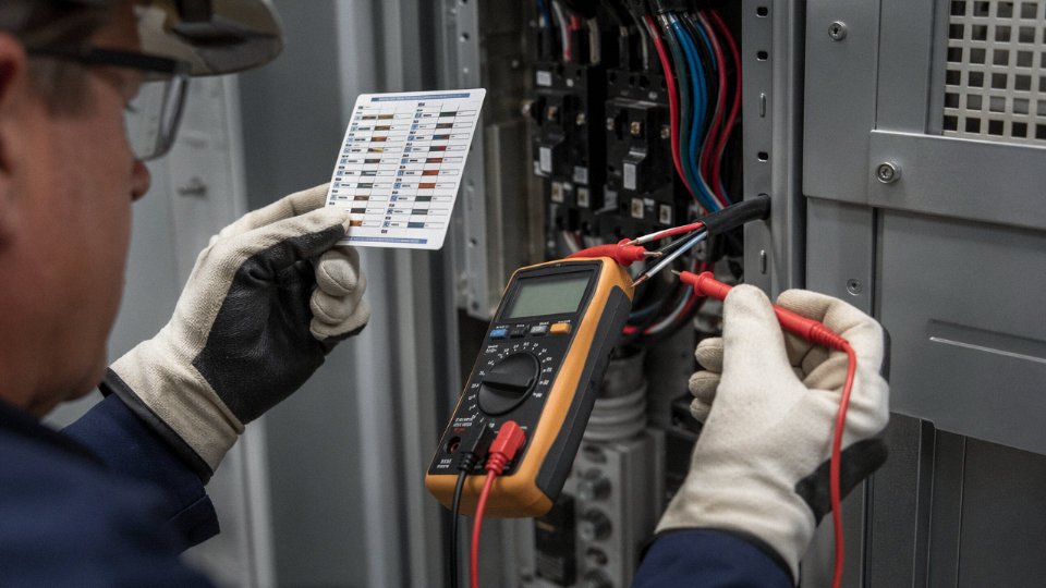
Once the NCV confirms the presence of AC voltage — or once you’ve followed LOTO and need to verify absence — a multimeter gives you the actual voltage figure. Set the meter to AC voltage above the expected maximum before probing: if you suspect a 400 V three-phase system, set to the 600 V or 750 V range, not the 200 V range.
Use the one-hand rule. Keep your free hand behind your back or in your pocket. Both hands on probes in a live panel is how current finds a path across your chest. Probe the phase-to-neutral voltage first — for a standard European LV system you expect roughly 220–240 V; phase-to-phase should read somewhere around 380–415 V depending on the installation. If you’re measuring a North American 120/240 V split-phase system, phase-to-neutral will be near 120 V and phase-to-phase near 240 V. Readings significantly outside these bands suggest either a non-standard supply, a voltage drop problem, or that you’re not looking at a standard LV circuit at all.
Clamp-On Ammeter as a Sanity Check
A clamp meter wrapped around a single conductor tells you the load current without breaking the circuit. This is a secondary check, not a primary identification method, but it’s useful: a 2.5 mm² conductor carrying 18–20 A is consistent with a normal LV distribution load. That same conductor carrying 80 A would be an overload alarm, and a reading of zero on a supposedly live circuit suggests a broken conductor or that the circuit isn’t what the label says.
Insulation Resistance Testing with a Megohmmeter
IR testing is where you confirm the quality of low-voltage insulation, not just the presence of voltage. The test voltage you apply depends on the cable’s rated voltage class: 250 V DC for extra-low-voltage cables, 500 V DC for standard LV cables up to 1 kV, and 1,000 V DC for cables rated at or approaching the 1 kV ceiling. Apply the test voltage for a full 60 seconds before reading.
IEC 60364 requires a minimum insulation resistance of 1 MΩ for low-voltage fixed installations.True
IEC 60364-6 specifies that the minimum acceptable IR value for LV circuits (up to 500 V) is 1 MΩ, measured with a 500 V DC test voltage applied for 1 minute. Circuits between 500 V and 1,000 V are tested at 1,000 V DC with the same 1 MΩ floor.
In practice, healthy new LV cable insulation reads well above 1 MΩ — often hundreds of megaohms. A reading that barely clears 1 MΩ on a relatively new installation warrants a closer look at splice points and terminations. Degraded insulation that reads below 1 MΩ could indicate moisture ingress, thermal damage, or wrong-class insulation installed in the wrong application. IR testing also helps expose a cable that looks like LV construction but has insulation too thin or too compromised to safely handle system voltage — something physical inspection alone can miss on aged or dirty cable.
TDR for Buried and Inaccessible Cables
Time Domain Reflectometry sends a fast electrical pulse down a cable and measures the time until the reflected signal returns. From that, you can calculate distance to a fault or impedance discontinuity. TDR is not a routine identification tool — it requires equipment that most maintenance teams rent rather than own, and interpreting the trace takes some practice. But on buried cable runs where the jacket markings are gone and the installation records are missing or unreliable, TDR can tell you cable type, approximate length, and whether there’s a fault point that might explain anomalous readings from earlier tests. Think of it as the escalation step when every other method leaves ambiguity.
A Hard Rule on Safety Before Any of This
No instrument replaces PPE and procedure. Insulated gloves rated for the voltage class you’re working in — Category II or III for most LV panel work — plus safety glasses are the minimum. For any work inside a panel where arc flash is possible, arc-rated clothing is not optional. Never trust a cable label or a circuit directory alone; labels get transposed, directories get out of date. Follow LOTO per OSHA 29 CFR 1910.147 before physical contact with any conductor you haven’t personally verified as de-energized with a calibrated tester. The few minutes that takes are not negotiable.
Identifying Low-Voltage Wiring in Specific Installation Environments: Residential, Commercial, and Industrial Contexts
Every identification method covered earlier — markings, physical inspection, electrical testing — has to be applied differently depending on where you’re standing. A 24 V doorbell transformer and a 480 V motor feeder are both technically “low voltage” under IEC 60038, but the field conditions, cable types, and real hazards around them are nothing alike. Context changes what you look for first.
Residential Settings
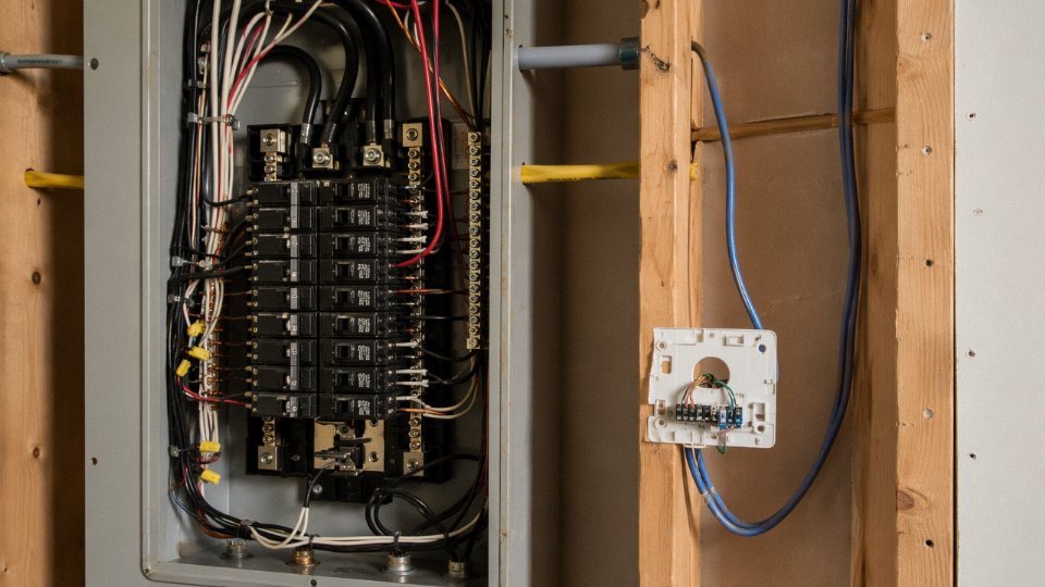
In a typical North American home, NM-B cable (the flat, gray or white sheathed product most people call Romex) dominates. Its characteristic flat jacket, printed AWG conductor size, and stamped voltage rating of 600 V make it among the easiest cables to identify on sight. Tracing a circuit from the breaker panel is usually the fastest approach: a 15 A single-pole breaker feeds a 14 AWG NM-B branch circuit at 120 V; a 20 A breaker means 12 AWG. The breaker ampere rating is a reliable secondary indicator of voltage class in residential work, because 120/240 V LV residential circuits almost never exceed 200 A service entrance size.
The pitfall in residential work is the low-voltage control wiring that runs alongside line-voltage cables inside the same wall cavities. Doorbell and thermostat circuits — typically 18–22 AWG, operating at 24 V AC off a small plug-in or hardwired transformer — look thin and unassuming. Electricians sometimes staple them right next to NM-B. A non-contact tester will still beep near the transformer output, which surprises some technicians who assume anything that thin must be dead. Always verify with a meter before cutting.
Commercial Buildings
Commercial electrical rooms are where things get more layered. You’ll typically see tray cable (TC), metal-clad cable (MC), and THHN conductors pulled in conduit, often mixed across multiple voltage levels in the same room. Panel schedule cross-referencing is the disciplined way to confirm LV status: pull the schedule, match the circuit number on the breaker or disconnect label to the load description, and trace conductors from there. Conduit fill and wire color also help — in a 277/480 V three-phase system, black, red, blue, and gray conductor colors (per NFPA 70) indicate the 480 V legs.
Here is where a common misunderstanding bites people: 277/480 V systems are still classified as low voltage under IEC and NEC definitions, but phase-to-phase exposure at 480 V is genuinely dangerous — far more so than touching a 120 V residential circuit.
277/480 V three-phase wiring is classified as low voltage under IEC 60038 and NEC definitions despite its higher shock hazard compared to residential 120 V circuits.True
IEC 60038 sets the LV upper boundary at 1,000 V AC; 480 V falls well within that range. The classification governs insulation and equipment ratings, not relative physiological danger.
The LV label does not mean low risk. Arc flash incident energy at 480 V bus can be catastrophic even in systems that never exceed the 1,000 V threshold.
Industrial Facilities
Industrial environments are where cable segregation becomes a life-safety issue, not just good practice. PLC and instrumentation wiring — 24 V DC two-wire loops, 4–20 mA analog signals, discrete I/O — frequently runs in the same cable tray rooms as 480 V motor feeders. NFPA 79 and IEC 60204-1 both require physical segregation between power and signal circuits, typically enforced through tray dividers or separate dedicated trays. In practice, gray conduit or gray tray sections typically carry signal and instrumentation wiring; orange conduit flags high-voltage mains circuits in many plants, though this isn’t universal and you should never assume a color scheme without confirming the site standard first.
A common field mistake: a maintenance tech chases a 4–20 mA signal wire across a tray, assumes everything in that tray is ELV or instrument-level, and reaches in without checking. One misrouted 480 V feeder in that tray — because a contractor didn’t follow the segregation drawing — and the result is a serious incident. Read the as-built drawings, not just the wire color.
Outdoor and Underground Installations
Direct-burial cables are where visual identification almost completely breaks down. A 600 V low-voltage direct-burial cable and a 15 kV medium-voltage distribution cable can look superficially similar once they’re both covered in black PE jacketing and mud. The practical identifiers are depth and documentation. LV direct-burial circuits typically sit at 450–600 mm depth per NEC Table 300.5 and equivalent IEC guidance; medium-voltage circuits are usually 900 mm or deeper. Cable route markers and warning tape (typically red or orange, buried 300 mm above the cable) provide above-grade clues, but these get moved, removed, or misplaced over decades of site work.
Use a utility locating service before any excavation. That’s not optional advice — it’s the only reliable method when documentation is incomplete.
Data Centers and Telecommunications Rooms
Structured cabling — Cat6, Cat6A, fiber-optic patch cords — carries no dangerous voltage under normal conditions. The visual identifiers are obvious: RJ45 terminations, color-coded patch cords (blue for standard data, yellow often for cross-connects or WAN circuits, white for voice in many conventions), and the characteristic thin, flexible jacket of 24 AWG or 26 AWG UTP. These are ELV circuits, well below any threshold that warrants the same caution as building power wiring.
Power over Ethernet (PoE) changes the calculation slightly. IEEE 802.3bt (PoE++) can deliver up to roughly 90 W at 48–52 V DC across all four pairs of a Cat6A cable. That’s still ELV — not dangerous under IEC 60950 touch-voltage definitions — but it’s enough to damage sensitive equipment if mishandled during patching and enough to start a fire in a damaged or undersized cable. Identify PoE circuits by the powered device at the far end (IP cameras, VoIP phones, wireless access points) and by whether the switch port shows PoE indicator LEDs. Don’t treat every blue patch cord as a dead piece of copper.
Common Mistakes That Lead to Misidentifying Voltage Class — and How to Avoid Them
Most electrical incidents on the plant floor don’t happen because someone was careless. They happen because someone was confident — and wrong. These are the mistakes that show up in incident reports, and a few of them are surprisingly common even among experienced trades.
Trusting Wire Color as Proof of Voltage Class
Color coding is a convenience, not a guarantee. IEC 60446 and NEC have different conventions, and neither of them governs what happened before the wire arrived at your site. A red conductor in a British installation from the 1980s was the live phase; in some older European DC systems, red was the negative rail. Imported cable — particularly equipment loomed in Asia or Eastern Europe and shipped as part of a machine skid — may follow entirely different internal color conventions that were never localized.
Renovated facilities make this worse. A single conduit run can contain original 1970s wire, a replacement pull from the 1990s, and a segment added last year, all with different color schemes. Color gets you to a hypothesis. A meter confirms it.
Assuming Small Wire Means Low Voltage
This one genuinely causes fatalities. A 1.5 mm² control cable looks innocuous. In a PLC cabinet inside a manufacturing cell, it almost certainly is low voltage. Route that same wire through the relay logic panel of a 33 kV substation, and it may be physically adjacent to terminals sitting at kilovolt potentials — or it may itself carry an induced voltage you didn’t account for.
Signal cables are sized for current, not for voltage isolation. Small diameter tells you nothing about what the conductor is near, what it’s coupled to, or what a fault condition could impose on it.
Reading Only One End of the Cable
Testing at the panel and then walking to the far end assuming the circuit is dead is how back-fed injuries happen. Capacitor banks, UPS systems, generator tie-ins, and photovoltaic arrays can all hold a circuit energized through a path you didn’t trace. Voltage can also be induced onto a de-energized conductor running in parallel with a live one over a long run — measurable, sometimes enough to shock, occasionally enough to damage sensitive equipment.
Test at the point of work. Not at the distribution board. Not at the previous junction. At the exact terminal you’re about to touch.
Skipping Insulation Resistance Testing on Old Installations
Visually, a rubber-insulated cable from 1982 can look perfectly fine. The jacket is intact, no cracks visible, no burn marks. But rubber insulation oxidizes and carbonizes over decades, and a conductor that reads 50 MΩ on day one might read 0.3 MΩ forty years later — well below the generally accepted 1 MΩ minimum threshold for low-voltage circuits under IEC 60364-6. The insulation is physically present but electrically it’s barely there.
If you’re working on any installation built before roughly 1995 and the IR test hasn’t been done recently, that cable is an unknown quantity regardless of what the visual inspection says.
Old rubber-insulated cables can appear visually intact while having dangerously degraded insulation resistance.True
Rubber insulation undergoes oxidation and carbonization over time. The outer surface may show no cracking, yet the dielectric properties deteriorate significantly, dropping insulation resistance to levels that create real shock and fault risk under normal operating voltage.
Confusing Rated Voltage With System Voltage
A cable marked 0.6/1 kV is rated to operate safely in systems up to 1,000 V AC. That marking says nothing about what voltage it’s actually carrying right now. It could be energized at 230 V, 400 V, or a test bench running 690 V. Always measure. The rating is a ceiling, not a readout.
Over-Relying on Labels in Renovated Buildings
Panel directories and circuit labels are maintained by whoever was last motivated to maintain them. In practice, after two or three renovation cycles, the label on breaker 14 may describe a circuit that was re-routed, split, or abandoned years ago. Physical and electrical testing must take priority over any documentation when there is any ambiguity at all.
Safe Identification Workflow — Quick-Reference Checklist
| Step | Action | Notes |
|---|---|---|
| 1 | Identify the installation environment | Residential, commercial, industrial, or substation — sets the risk baseline |
| 2 | Check cable markings and print line | Voltage rating, standard, conductor size |
| 3 | Assess insulation thickness and jacket construction | Compare against known LV ranges (roughly 0.6–1.2 mm for 1.5–16 mm²) |
| 4 | Verify color coding against the applicable local standard | Do not treat color as conclusive in imported or older equipment |
| 5 | Use a non-contact tester at the point of work | Confirms presence of AC field; does not confirm voltage level |
| 6 | Measure with a CAT-rated multimeter at the actual work point | Confirms actual system voltage; account for possible back-feed |
| 7 | Run an IR test if the installation is more than ~15–20 years old or origin is unknown | Insulation resistance below 1 MΩ means the cable should not be trusted regardless of visual condition |
None of these steps is redundant. Each one catches a failure mode that the previous step misses.
How Cable Construction Standards and Quality Certifications Help You Identify Voltage Rating at a Glance
Once you move past physical inspection and basic electrical testing, the fastest and most reliable way to confirm a cable’s voltage rating is often sitting right in the paperwork — or stamped directly into the jacket. Standards markings and certification marks are not bureaucratic formalities. They encode the cable’s entire construction specification, including the voltage class it was built and tested to withstand.
What the Standard Number Printed on the Jacket Actually Tells You
IEC 60502-1 governs power cables rated up to 1 kV AC. If that standard number appears on the cable jacket, the cable was designed, insulated, and sheathed to meet low-voltage power cable requirements — full stop. Similarly, UL 83 covers thermoplastic-insulated wires for the North American market; a cable printed with “UL 83” and a 600 V rating is a UL-listed low-voltage wire. BS 6004 is the British standard for PVC-insulated cables, typically rated to 300/500 V or 450/750 V, and those voltage designations appear directly in the marking string. AS/NZS 5000 covers cables for the Australian and New Zealand market, usually with a 0.6/1 kV rating for power cables.
The voltage designation itself is printed as a two-number code: 0.6/1 kV means 600 V phase-to-earth, 1,000 V phase-to-phase. That’s the IEC format. When you see it on the jacket, you know immediately this is a low-voltage cable under IEC 60038 (AC up to 1,000 V). A 300/500 V designation means it’s a lighter-duty LV cable, common in flexible cords and wiring accessories. If the jacket shows no voltage designation at all, that’s already a red flag.
Decoding IEC Cable Type Designation Codes
The letter-code system in IEC cable designations carries more information than most site engineers realize. In German-origin IEC nomenclature, which is widely used internationally: N indicates PVC insulation on the conductor, Y indicates a PVC outer sheath, 2X means XLPE insulation, and W signals weather-resistant or outdoor-rated construction. So “NYY” is a PVC-insulated, PVC-sheathed power cable — standard low-voltage distribution cable, rated 0.6/1 kV. “N2XY” is XLPE-insulated with a PVC sheath, also 0.6/1 kV, but with better thermal performance. Once you know the letter key, you can decode the construction from the type code alone, without unrolling a meter of cable.

Certification Marks and How to Verify Them
CE marking under the Low Voltage Directive (LVD 2014/35/EU) confirms that the cable was designed and tested within the 50–1,000 V AC range and meets EU safety requirements. The UL Listed mark means UL has independently tested and listed that specific cable construction. CSA certification covers the Canadian market with similar scope. CCC (China Compulsory Certificate) is mandatory for cables sold in China and covers voltage rating, insulation material, and conductor construction.
Here’s the practical point: any of these marks can be counterfeited. Verification matters. UL’s online certification database (UL Product iQ) lets you check whether a specific cable manufacturer and product are genuinely listed. CE marking should be backed by a Declaration of Conformity document, which a legitimate supplier provides without hesitation. CCC certificates are verifiable through the CNCA database.
A CE mark alone is sufficient proof that a cable meets IEC low-voltage requirements.False
CE marking under the LVD confirms the product falls within the LVD's voltage scope and the manufacturer has declared conformity, but it is a self-declaration framework. Independent verification via type test reports or third-party certification is needed to confirm the cable genuinely meets the underlying IEC construction standard.
Factory Test Reports and Type Test Certificates as Identification Tools
A proper low-voltage cable ships with documentation that directly confirms voltage class compliance. A Hi-Pot (voltage withstand) test report will show the test voltage applied — for a 0.6/1 kV cable under IEC 60502-1, that’s typically 3.5 kV AC for 5 minutes on the completed cable. Insulation resistance test values confirm the insulation system integrity. Conductor resistance values per IEC 60228 confirm the conductor cross-section matches what’s printed on the drum label.
Jinda supplies IEC type test certificates, factory acceptance test (FAT) reports, and drum-level test records as standard documentation for procurement and project teams. That means a site engineer or procurement manager can verify the voltage rating before the cable drum is ever moved to the installation area — not after something goes wrong. On large projects where multiple cable types arrive simultaneously, this drum-level traceability is how you avoid the genuinely unpleasant situation of pulling the wrong cable through conduit.
Counterfeit and substandard cables routinely fail on exactly these checks: insulation walls are thinner than the standard specifies, the standard number is printed but no test certificate exists, or the certificate references a test lab that cannot be verified. If a supplier cannot produce documentation on request, that tells you what you need to know.
Frequently Asked Questions About Identifying Low-Voltage Wire
Can a wire be both low voltage and high voltage depending on where you measure?
Yes, and this catches people out more often than you’d think — especially inside distribution panels, transformer enclosures, and variable-frequency drive cabinets. The primary side of a step-down transformer might carry 11 kV or 33 kV, while the secondary feeds a standard 400 V LV distribution board, and both conductors can be physically close together inside the same metal enclosure. Identifying the cabinet as “low voltage” and then reaching for an unlabeled terminal is exactly the kind of mistake that lands people in hospital.
Always identify the specific conductor you intend to work near, not the enclosure type. Test every conductor individually before you touch anything.
Is 240 V considered low voltage?
Yes. 240 V AC sits comfortably within the IEC 60038 low-voltage ceiling of 1,000 V AC, and the NEC definition aligns closely. That classification is a regulatory and construction category, not a safety comfort level. A 240 V shock is fully capable of causing ventricular fibrillation, and the arc flash energy at 240 V can cause serious burns. LV classification means the cable insulation, termination hardware, and safety procedures are designed for that voltage range — it does not mean the voltage is harmless. Full low-voltage safety procedures apply: appropriate PPE, lockout/tagout, and verified dead before contact.
240 V AC is classified as low voltage under IEC 60038 and NEC definitions.True
IEC 60038 defines low voltage AC as systems up to 1,000 V; 240 V falls well within this range. NEC Article 100 similarly places 240 V within the low-voltage category for wiring methods and equipment ratings.
How do I tell a 12 V landscape wire from a 120 V outdoor feeder without a meter?
Physical differences are fairly obvious once you know what to look for. A 12 V landscape wire is usually 16–18 AWG, thin and flexible, often two-conductor parallel construction with insulation rated at 300 V — you’ll typically see “300V” printed on the jacket. It runs back to a plug-in or low-profile transformer near the house. A 120 V outdoor feeder is a different animal: heavier gauge (10–14 AWG is typical), likely UF-B cable rated 600 V, or pulled through schedule 40 PVC conduit. The jacket is noticeably stiffer and thicker. That said, use a non-contact voltage tester anyway. Landscape wiring systems occasionally get modified, someone runs a 120 V circuit through the same trench, and you won’t know by looking.
What does 0.6/1 kV on a cable label actually mean?
The two figures describe two distinct voltage conditions. The 0.6 kV rating covers voltage stress between any single conductor and earth — ground fault scenarios, effectively. The 1 kV figure covers the voltage between any two conductors in the cable under normal operating conditions. Together they define the maximum electrical environment the cable is approved to operate within continuously. A cable marked 0.6/1 kV is suitable for systems up to 1,000 V phase-to-phase, which covers most standard LV distribution networks globally. If your system exceeds either figure, you need a cable with a higher designation.
Can I use a smartphone app to identify wire voltage?
No. There is no phone app that can safely or accurately measure live conductor voltage. Some apps claim to detect AC fields via the phone’s microphone or magnetometer — they are not calibrated instruments, they have no standardized accuracy, and they carry no safety certification. For any safety decision involving a potentially live conductor, use only a non-contact voltage tester rated for the expected range, or a calibrated multimeter with properly rated CAT probes. Phones near live MV conductors also carry real arc flash and induction risks. Don’t experiment.
How often should insulation resistance tests be carried out on low-voltage installations?
It depends on the environment and use intensity. IEC 60364-6 establishes initial verification testing at commissioning, then periodic inspection intervals based on installation type. For commercial buildings — offices, retail — a 5-year periodic inspection cycle is widely adopted in practice. Industrial plants with high mechanical stress, vibration, heat cycling, or chemical exposure warrant annual IR testing on critical circuits, and some continuous-process facilities test quarterly on motor feeder cables. The honest answer is: follow your national adoption of IEC 60364-6, then adjust downward based on actual operating conditions. A cable feeding a conveyor running three shifts deserves more frequent attention than office lighting.
Does cable color alone definitively identify voltage class?
It does not. Color coding identifies conductor function — live, neutral, protective earth — within whatever system voltage happens to be installed. Brown is live in IEC color-coded systems, but brown at 24 V DC and brown at 400 V AC look identical. Green-yellow is always a protective earth, regardless of whether the system runs at 48 V or 690 V. In older industrial plants especially, you’ll find non-standard color schemes, field repairs with whatever wire was on the shelf, and repurposed conduits carrying circuits added over decades. Color is a starting point for understanding conductor role, not a shortcut for confirming voltage level.
What is the minimum safe distance to keep from an unidentified wire until testing is complete?
Until you’ve confirmed the voltage class, assume the worst practical case for the environment you’re working in. In most industrial facilities, that means treating an unidentified cable as potentially medium voltage — up to roughly 15 kV — and maintaining at least 300 mm clearance with no part of your body, no uninsulated tool, and no conductive material bridging that gap. Use insulated tools rated for the MV range for any initial physical handling, and use a non-contact voltage tester rated above 1,000 V for the first detection pass. Once you’ve confirmed the conductor is LV or de-energized, normal LV procedures apply. The 300 mm figure is conservative for most LV environments, but it costs nothing to be conservative before you know what you’re dealing with.
Sourcing Low-Voltage Cable You Can Identify and Trust: What to Require from Your Supplier
Getting the identification methods right in the field only solves half the problem. The other half happens earlier — at the procurement stage, before a single drum ships to site. Cables that arrive with incomplete markings, inconsistent insulation geometry, or missing test documentation force field teams into exactly the guesswork this article is trying to eliminate. Tight supplier requirements upstream make every downstream identification task faster and safer.
The Five Documents That Should Be Non-Negotiable on Every LV Cable Order
Start with an IEC type test certificate issued by an accredited third-party laboratory — not a factory-internal test, an actual CNAS, KEMA, BASEC, or equivalent lab report. This confirms the cable design was validated against the full IEC 60502-1 or relevant product standard, including voltage withstand, bending, and conductor resistance. Without it, you have no independent confirmation the insulation thickness or compound grade matches what’s printed on the jacket.
Each drum also needs a factory acceptance test (FAT) report specific to that drum number. Type tests cover the design; FAT reports cover the actual production batch. These are different things, and a lot of buyers conflate them.
The drum card — physically attached to the drum flange — should show conductor resistance per unit length, insulation resistance, and the voltage withstand test result for that specific length of cable. If a field team later queries whether a drum’s insulation is intact, that card is the first reference point. Treat its absence as a red flag.
Material certificates for the conductor (copper or aluminum, with conductivity and purity data referenced to the relevant IEC or ASTM standard) and for the insulation and sheath compound (PVC, XLPE, or other — with the compound grade documented) complete the picture. You want traceability from raw material through to finished cable.
Finally, a certificate of conformity explicitly referencing the applicable standard — IEC 60502-1, BS 6004, AS/NZS 5000.1, or whatever governs your project — ties the whole documentation package together. Procurement teams in regulated industries or on export projects will usually need this for customs clearance and commissioning records anyway.
Meter Marks and Drum Length: A Small Detail That Catches Big Problems
Quality manufacturers print sequential running-meter marks along the cable jacket, typically every 1 m or every 500 mm. This lets a receiving team verify the drum contains the ordered length before it’s even uncoiled, and it gives installers a continuous check for insulation damage — a splice or repair in the factory will break the meter-mark sequence. Volume-only suppliers frequently skip this or print marks inconsistently. In practice, a 500 m drum that actually contains 480 m discovered mid-installation creates real schedule damage.
What a Serious Quality Infrastructure Looks Like Behind the Cable
ISO 9001 certification matters, but look past the certificate to the specific process controls. Does the manufacturer run spark testing at 100% of production output? Spark testers apply a continuous high-frequency AC voltage to the moving cable — typically set at 6 kV to 15 kV depending on voltage class — and flag any pinhole or thin spot in the insulation instantly. A plant running spark tests on every meter of every cable produces consistent insulation geometry. One that spot-tests by batch does not, and that difference shows up in the field when you’re trying to interpret insulation resistance readings.
In-house high-voltage test bays allow the manufacturer to conduct voltage withstand testing on finished drums without sending them to an external lab, which speeds up FAT documentation delivery. Third-party audit history — BASEC surveillance, Bureau Veritas factory audits, or similar — gives buyers an independent view of whether day-to-day production actually matches the certified processes.
Spark testing on 100% of cable production output reliably detects insulation pinholes that batch sampling would miss.True
Spark testers apply continuous high-voltage AC to the moving cable surface; any insulation void causes a discharge and triggers an alarm, providing 100% inline coverage that statistical batch sampling cannot replicate for randomly distributed defects.
Jinda’s Supply Capability for International LV Cable Projects
Shandong Jinda operates across five production bases in China with roughly 470,000 m² of manufacturing floor space and more than 1,000 employees across R&D, production, and technical support functions. For LV power cable specifically, the production range runs from 1.5 mm² single-core flexible wire through to 400 mm² multicore armored power cables, manufactured to IEC 60502-1, BS 6004, BS 6346, AS/NZS 5000 series, and other international standards depending on the destination market. With export history spanning 50+ countries, Jinda can usually point procurement teams to reference customers operating in the same regulatory environment as their project — which matters when you need to verify that a supplier actually understands your local approval requirements, not just your voltage class.
Technical Support That Extends Past the Delivery Gate
One area where international cable procurement regularly breaks down is the gap between what’s specified on paper and what arrives on site. Jinda’s standard process for international orders includes a free pre-order technical review of cable schedules — a Jinda engineer will check conductor sizing, insulation class, armoring, and standard compliance against the project specification before production is confirmed. Each shipment is accompanied by drum-specific test reports, not generic batch documentation. Post-delivery, a dedicated after-sales engineering team is available to work through field identification questions, installation queries, or any discrepancy between the drum card data and field measurements.
If you’re currently specifying LV cables for a new project and want a compliant cable recommendation, a sample for evaluation, or a competitive quotation backed by full IEC documentation, contact Jinda’s international sales team directly. Bring your cable schedule and the applicable installation standard for your region — the technical review is free, and it’s the fastest way to confirm you’re ordering cable you can identify, trust, and install with confidence.




