Specifying the wrong cable type — running armored power cable where a multi-core control cable belongs, or the reverse — creates problems that don’t announce themselves until something fails. A misapplied cable might pass initial commissioning, then cause intermittent signal noise in a PLC loop, or degrade under mechanical stress until a ground fault shuts down a production line mid-shift. Depending on how deep the cable run is buried or how tightly it’s routed through conduit, a replacement job can run anywhere from a few hundred to tens of thousands in labor and downtime alone, not counting the cable itself.
Control cables and armored cables serve fundamentally different functions. Control cables — typically rated at 300/500 V or 450/750 V, with conductors from 0.5 mm² to 10 mm² — carry instrumentation signals and low-power switching circuits. Armored cables, most often protected by steel wire or steel tape, are built for power distribution from 0.6/1 kV up to 33 kV or higher, with conductors that can exceed 400 mm², and their armor adds meaningful mechanical and tensile protection that a control cable simply isn’t designed to provide.
What makes this genuinely confusing in practice is that some cables straddle the line — armored control cables exist, multi-core power cables get pulled into signal-adjacent applications, and the terminology shifts between IEC standards, regional codes, and whatever a supplier’s catalog happens to call things. Understanding where the real engineering boundaries sit changes how you specify, procure, and install both types.
Anatomy of a Control Cable: Conductor Count, Insulation, and Signal-Integrity Design
A control cable is not simply a small power cable. The distinction matters on the factory floor, where a wiring crew pulling the wrong product into a control panel tray can create noise problems, commissioning headaches, or outright signal failures that take days to trace.
What “Control Cable” Actually Means at the Construction Level
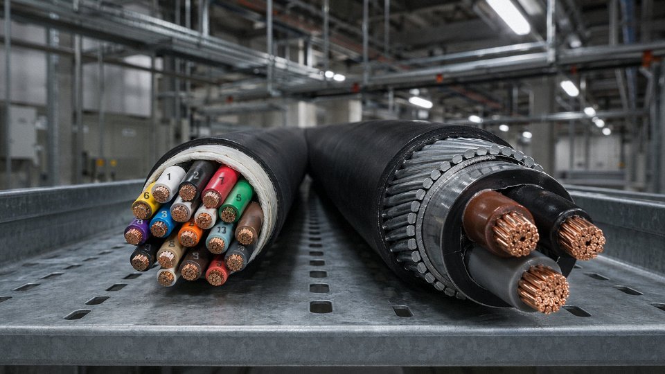
Control cables are multi-core cables designed to carry switching commands, instrumentation signals, and low-level control loops — not bulk energy. Core counts run from as few as 2 up to 61 in a single cable, occasionally higher for dense process-control installations. Voltage ratings sit at 300/500 V or 450/750 V under IEC 60227, which reflects the nature of the duty: these cables route 24 V DC logic signals, 4–20 mA analogue loops, or 110/230 V switching circuits, not three-phase distribution currents. Using a cable rated at 0.6/1 kV for this application wastes money; using a control cable where 0.6/1 kV is required is a safety and compliance failure.
Conductors: Material, Cross-Section, and Why Stranding Is Not a Footnote
Conductors in control cables are plain annealed copper or tinned annealed copper. Tinning matters in humid or mildly corrosive environments — marine panel rooms, chemical plant junction boxes — because it resists the surface oxidation that quietly degrades termination resistance over a few years. Cross-sections typically run from 0.5 mm² to 10 mm², with 0.75 mm², 1.0 mm², and 1.5 mm² covering the vast majority of PLC I/O, relay switching, and instrumentation wiring.
Fine stranding is where control cable design diverges clearly from anything optimized purely for power. A 1.0 mm² conductor built to Class 5 (flexible) stranding — 32 wires or more, depending on the standard — bends through the tight radius of a cable duct or around panel door hinges without fatiguing the copper. Coarser Class 2 stranding in the same cross-section is stiffer and will work loose at ferrule terminations if the cable moves repeatedly. In practice, panel builders specify flexible stranding almost automatically; the mistake usually happens when a procurement manager substitutes a Class 2 product because it was cheaper or locally available.
Insulation: PVC vs. XLPE, and What the Temperature Rating Actually Affects
PVC insulation rated to 70°C is the workhorse choice — cost-effective, easy to terminate, and compliant with IEC 60227-3 and IEC 60227-5 for fixed and flexible wiring respectively. It handles most industrial control environments without issue. XLPE insulation, rated to 90°C continuous, is the better call when the cable runs near heat sources, through areas with aggressive oils, or where a longer service life justifies the modest price premium. XLPE also has lower dielectric loss, which becomes relevant in high-frequency instrumentation circuits, though for most 4–20 mA loops the difference is negligible.
XLPE insulation in control cables can operate continuously at 90°C, versus 70°C for standard PVC, under IEC 60502 construction guidelines.True
IEC 60502-1 and related IEC 60227 series specify maximum continuous conductor temperatures of 70°C for PVC-insulated cables and 90°C for XLPE-insulated cables under normal operating conditions. These ratings are well established across international standards and industry practice.
Core Identification: A Commissioning Issue, Not a Cosmetic One
A 37-core cable with ambiguous core marking is a genuine commissioning problem. Electricians spend hours continuity-testing and labeling cores that should have arrived pre-identified. Good control cables use a combination of numbered insulation printing and color-coded grouping — typically following IEC 60227 or GB/T 9330 conventions, where cores are numbered sequentially and printed digits repeat at short intervals along the insulation. EN 50525 harmonizes much of this across European markets. On large installations with dozens of identical-looking multicore cables landing in the same marshalling panel, traceability built into the cable itself is not a luxury.
Shielding Options and EMI Suppression
Unshielded control cable works fine for relay switching and motor start/stop circuits where noise immunity is not critical. Once analogue signals — temperature transmitter outputs, pressure transducer loops, encoder feedback — enter the picture, shielding becomes necessary.
Overall aluminum-foil with a drain wire is the standard cost-effective solution, attenuating capacitively coupled interference reasonably well. Braided copper shielding offers lower transfer impedance and handles higher-frequency interference better, at a cost and weight penalty of roughly 20–40% depending on braid coverage. For applications involving multiple independent analogue channels in a single cable — common in process plants trying to minimize conduit fill — individual pair or triad screening isolates each loop, preventing crosstalk between channels that would otherwise share a common overall shield. The drain wire must be grounded at a single point (usually the control panel end) to avoid creating a ground loop that introduces exactly the 50/60 Hz noise the shield was meant to block. That single-point grounding rule gets violated more often than it should, usually by a subcontractor who is not told it matters.
Anatomy of an Armored Cable: Steel Wire, Steel Tape, and the Mechanics of Crush and Pull Resistance
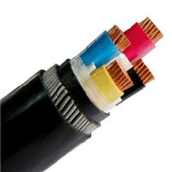
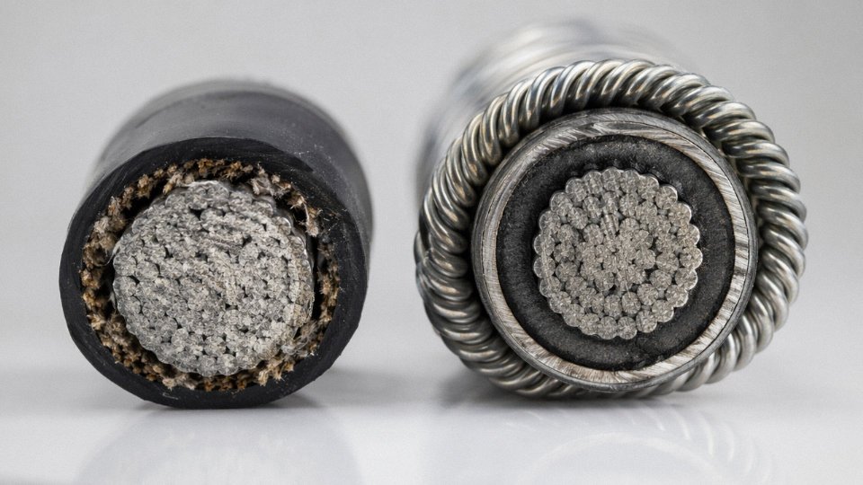
An armored cable is, at its core, any insulated cable — single-core or multi-core — that incorporates a metallic armor layer positioned between the inner sheath and the outer sheath. That definition sounds simple. The engineering behind it is not.
The armor layer is not decorative. It exists to handle mechanical loads that the insulation and sheath materials simply cannot absorb: the axial tension of a cable being pulled through conduit or across a cable tray over hundreds of meters, the radial crushing load of backfill soil or vehicle traffic above a direct-burial trench, or the incidental impact of a dropped tool in a substation cable basement. Strip the armor off and you have a cable that looks similar but fails in the field under conditions that occur routinely.
Steel Wire Armoring: The Workhorse for Burial and High-Tension Pulls
Steel wire armoring (SWA) consists of a layer of galvanized steel wires, typically 0.8 mm to 3.15 mm in diameter depending on cable size, helically applied over the inner sheath (also called bedding). The bedding layer — usually PVC or PE, somewhere in the range of 0.8 mm to 2 mm thick — serves as a mechanical buffer between the insulated cores and the armor, preventing the wire helices from biting into the insulation under load.
SWA is the right choice for underground direct burial and for long cable pulls where tensile loading during installation is a real concern. A medium-sized SWA cable — say, a 4-core 95 mm² unit — can handle axial tensile loads exceeding 10 kN, sometimes considerably more depending on the number and diameter of armor wires and the overall cable construction. That figure matters when a contractor is pulling 200 m of cable through a duct with multiple bends; without adequate tensile capacity, armor deformation or conductor elongation becomes a genuine risk.
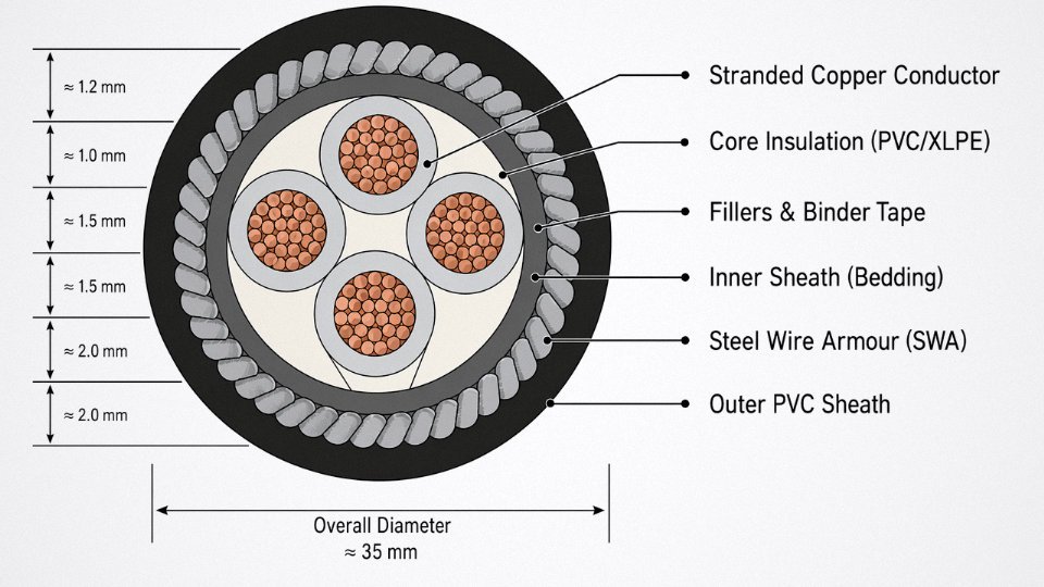
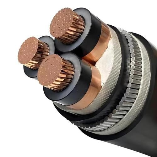
The full construction stack from inside out runs: conductor → conductor insulation → fillers and binder tape → inner sheath (bedding) → SWA layer → outer PVC or HDPE sheath. Outer sheath thickness typically falls between 1.8 mm and 3.5 mm for most distribution-voltage cables, with heavier walls on cables rated above 6/10 kV. Minimum bend radius for SWA cables is usually specified at 6× to 8× the overall cable diameter — tighter than that and you risk cracking the armor wire galvanizing or, worse, kinking the conductors.
Steel Tape Armoring: Radial Crush, Not Axial Pull
Steel tape armoring (STA) uses one or two overlapping helical steel tapes rather than individual wires. It provides excellent resistance to radial compressive loads — someone laying heavy conduit across an unburied cable run, for instance, or a cable routed through a cable duct that sees periodic point loading. What STA does not give you is significant tensile strength. The tapes can separate under axial load. Specifying STA where a long pull is involved is a mistake that shows up during installation, not during testing.
Aluminum Wire Armoring: The Single-Core Exception
For single-core AC power cables, steel armor is genuinely problematic. A single current-carrying conductor induces a longitudinal magnetic flux, and a closed ferromagnetic loop — steel wires or tapes — around it will experience eddy-current losses and heating that can be substantial at load currents above a few hundred amperes.
Steel wire armoring on single-core AC cables causes measurable eddy-current heating at high load currentsTrue
A closed ferromagnetic loop around a single AC conductor acts as a shorted secondary transformer winding; eddy currents induced by the changing magnetic flux generate heat, reducing cable ampacity and increasing energy losses — this is well-documented in IEC 60502 and standard cable engineering references.
Aluminum wire armoring (AWA) solves this. Aluminum is non-ferromagnetic, so the eddy-current loss mechanism is largely absent. AWA adds mechanical protection — crush resistance especially — while keeping thermal performance acceptable. In practice, most single-core medium-voltage cables you see in substations and large industrial switchgear installations use AWA for exactly this reason.
Standards That Actually Govern Construction
The primary references for armored cable construction and testing are IEC 60502-1 (cables rated up to 1 kV), IEC 60502-2 (1 kV to 30 kV), BS 5467 (the UK standard most procurement teams in Africa and the Middle East still specify by name), and GB/T 12706 (the Chinese national standard, broadly aligned with IEC 60502 but with some dimensional differences that matter when mixing cable sources on a project). These standards define armor wire diameter tolerances, tensile test requirements, minimum sheath thicknesses, and voltage test levels. If a supplier cannot provide a test report referencing one of these standards, that is a procurement conversation worth having before the order goes out.
Head-to-Head Electrical Specifications: Voltage, Current Capacity, and Signal Integrity Parameters
The fastest way to frame the difference electrically is this: control cables are designed around signal fidelity and multi-core manageability; armored power cables are designed around kilowatts moved efficiently with mechanical survivability. Those are genuinely different engineering goals, and the specifications reflect that all the way down to conductor resistance tolerances.
Rated Voltage: A Wider Gap Than Most People Expect
| Cable Family | Typical Voltage Ratings |
|---|---|
| Control cable | 300/500 V · 450/750 V |
| Armored power cable (LV) | 0.6/1 kV |
| Armored power cable (MV) | 3.6/6 kV · 6/10 kV · 8.7/15 kV · 12/20 kV · 26/35 kV |
The notation “U₀/U” matters here — U₀ is phase-to-earth voltage, U is phase-to-phase. A control cable rated 450/750 V is built for instrument and control panel wiring where you might see 230 V phase-to-neutral at most. An SWA cable at 0.6/1 kV is designed to sit on a distribution board feeding a 400 V three-phase bus, and cables rated 8.7/15 kV or higher belong in medium-voltage switchgear and substation feeders. Running a 450/750 V control cable as a substitute feeder in a 0.6/1 kV system is a code violation, not just poor practice — the insulation wall simply isn’t there.
Current-Carrying Capacity: Same Cross-Section, Different Numbers
This trips up procurement teams regularly. A 2.5 mm² conductor is a 2.5 mm² conductor — but a 2.5 mm² core inside a 12-core control cable bunched with eleven other loaded cores will derate to somewhere around 60–75% of the same conductor’s free-air rating, depending on ambient temperature and whether it’s in conduit or tray. Control cables are routinely used at very low currents — a 4–20 mA loop draws milliamps, and a digital output to a solenoid valve might pull 0.5–1 A. The insulation system (typically PVC or XLPE at thinner walls than a power cable) and the grouping factors in IEC 60364-5-52 assume modest thermal loading. A 2.5 mm² armored power cable core, by contrast, is sized expecting continuous load current — potentially 20–27 A for a single circuit in free air at 30 °C, depending on insulation type and installation method. Same copper cross-section; the application context changes everything.
Loop Resistance and IEC 60228 Class 2 Conductors
Most control cables use IEC 60228 Class 2 stranded conductors. At 20 °C, a 1.5 mm² Class 2 conductor runs roughly 12.1 Ω/km, a 2.5 mm² around 7.4 Ω/km, and a 1.0 mm² around 18.1 Ω/km — these are maximum values; actual measured resistance is usually a few percent lower. For a 4–20 mA loop running 500 meters each way (1,000 m loop length), a 1.5 mm² pair gives you loop resistance around 12 Ω. Most HART-compatible transmitters tolerate loop resistance up to roughly 250–1,000 Ω depending on supply voltage, so that’s fine. But if someone substitutes a thinner conductor to save money on a long run, loop resistance climbs and the transmitter may rail at the low end — you’ll see the signal floor shift, which gets misdiagnosed as a calibration problem. I’ve seen that exact fault chase a maintenance team for two days.
IEC 60228 Class 2 specifies maximum DC resistance per kilometer for stranded conductors at 20°C, and a 1.5 mm² conductor must not exceed approximately 12.1 Ω/km.True
IEC 60228:2004 Table 1 lists maximum resistance values for Class 2 conductors; 1.5 mm² stranded copper has a maximum of 12.1 Ω/km at 20°C, which is a standard design reference for control and instrumentation cable selection.
Capacitance, Inductance, and Why Fieldbus Engineers Care
Screened control cables typically exhibit capacitance between 80 and 200 pF/m, depending on conductor spacing, insulation material, and screen geometry. For a conventional 4–20 mA loop this is a secondary concern — the bandwidth is low. For PROFIBUS DP, however, IEC 61158 Type 3 cable specifies a maximum capacitance of 30 pF/m and characteristic impedance of 135–165 Ω. Exceed the capacitance budget and signal reflections degrade bus integrity, particularly at 12 Mbit/s over longer segments. Inductance per meter typically falls between 0.6 and 1.0 µH/m for twisted-pair screened cable, and the twist pitch affects this — tighter twist means better common-mode rejection. Armored power cables are not characterized for these parameters because nobody is running PROFIBUS on them. Their capacitance between cores is higher and inconsistent, and the steel armoring can introduce permeability effects that make inductance values unpredictable.
Derating: Two Different Conversations
Grouping factors, ambient temperature correction, and burial depth derating apply to both cable families, but the weighting is different. For armored power cables, burial depth and soil thermal resistivity dominate the calculation — a cable in dense, dry sand dissipates heat worse than one in moist clay, and MV cable sizing in direct burial often ends up one or two cross-section steps larger than the theoretical minimum purely because of thermal derating. For control cables, grouping is the main concern: a 37-core or 61-core control cable trunking run generates negligible heat at signal currents, but if some of those cores carry 24 VDC solenoid loads with 1–2 A per circuit, the bundle can see meaningful temperature rise. The practical rule in most plants I’ve worked in — keep power-loaded cores in control cables below about 30% of the total core count, or route them separately. It’s not always practical, but it avoids thermal derating surprises during commissioning.
Mechanical and Environmental Protection: Where Armoring Wins and Where It Adds Unnecessary Weight
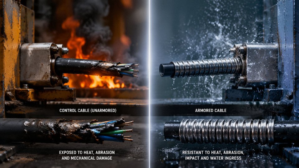
The armoring layer on a cable exists to solve four specific physical problems. Get clear on which of those problems you actually have before you specify it — because SWA adds real weight, real cost, and real installation labor. Armoring is not a quality upgrade. It’s an engineering response to a defined hazard.
The Four Hazard Categories Armoring Is Built For
External mechanical impact is the most obvious one — a cable run under a road, through a trench shared with other utilities, or across a factory floor where forklift traffic is a fact of life. Steel wire armoring (SWA) absorbs crush and impact loads that would split a plain PVC sheath and breach the insulation underneath. Steel tape armoring (STA) handles radial crush well but offers less tensile resistance, which matters for the second hazard.
Tensile stress during installation or ground movement is where SWA earns its keep in direct-burial applications. Pulling a cable through a long conduit run, or dealing with soil settlement and frost heave in cold climates, puts longitudinal load on the cable. A medium multi-core SWA cable can handle tensile loads upward of 10 kN depending on conductor count and armoring wire diameter — an unarmored cable under the same stress will stretch, separate conductors from terminals, or fail at the gland.
Rodent attack is underestimated, particularly in agricultural facilities, food processing plants, and cable runs through vegetation. Rats and squirrels chew through PVC sheaths with no difficulty. Steel wire armoring is not impenetrable, but it’s a serious deterrent — enough that most direct-burial specifications in rat-prone environments require it.
Hydrostatic pressure in flooded conduits matters most in below-grade cable ducts, pump station trenches, and coastal infrastructure. Water ingress alone doesn’t destroy a well-made insulated cable immediately, but sustained hydrostatic pressure accelerates insulation degradation over years. Armored cables with PE outer sheaths are the standard answer here; PVC absorbs moisture slowly over time and is a poor choice for permanently wet environments.
Direct Burial: Depth Rules and What They Actually Mean
Per IEC practice and most national derivatives, LV armored cables in direct-burial applications typically go at 0.5 m depth under footpaths and 0.6 m or deeper under roads, with a sand bed and cover tiles above. These aren’t arbitrary — they’re calculated to keep mechanical loads from vehicle traffic below the cable’s crush threshold.
An unarmored control cable in the same trench needs a rigid conduit or a concrete-encased duct. Full stop. Skipping the conduit to save time on a retrofit is one of those decisions that looks fine during commissioning and fails at 2 a.m. eighteen months later when a cable gets nicked by a follow-on excavation.
Where Armoring Is Overkill
In a clean manufacturing plant — cable trays inside a control room, enclosed plastic cable ducts in a dry MCC building, above-ground steel trunking in a pharmaceutical facility — unarmored multicore control cables are entirely adequate. The tray or duct provides the mechanical protection. Adding SWA in these conditions just means heavier cable tray loads and harder terminations for the electricians running the job.
Roughly, SWA armoring adds somewhere between 0.8 and 2.5 kg per meter to a medium multi-core cable, depending on conductor count, cross-section, and wire diameter. That’s not trivial. On a 200-meter cable bridge spec’d with thirty or forty runs, the cumulative weight difference between armored and unarmored can push you into a structural redesign of the support steelwork. I’ve seen that caught late — and it’s an expensive late.
The Flexible Armored Middle Ground
Mining draglines, tunnel boring machines, and mobile quarry equipment need cables that flex continuously while still resisting mechanical damage. Standard SWA is not flexible enough — bending it repeatedly work-hardens the steel wires and causes fatigue cracking. The solution is braided steel wire armoring or chain-mail (interlocked steel tape) armoring, which maintain flex life while providing meaningful cut and abrasion resistance. These constructions sit between a standard control cable and a rigid SWA power cable. They’re typically specified to IEC 60502 or relevant mining standards, and they need correctly rated flex-rated glands — a standard SWA gland will not terminate them properly.
PVC outer sheaths are suitable for all direct-burial cable applicationsFalse
PVC absorbs moisture gradually under sustained hydrostatic conditions. PE sheathing is the correct choice for cables in permanently wet or below-grade environments where long-term moisture resistance is required.
Sheath Material: A Decision That Outlasts the Installation
PVC outer sheathing is standard, cost-effective, and fine for most above-ground industrial environments. The problem is specifying it by default without asking about the end-use conditions. LSZH (low smoke zero halogen) sheathing is mandatory in tunnels, confined spaces, and public buildings where halogen-based combustion gases are a life-safety concern — the material costs more and is somewhat less mechanically robust than standard PVC, but in a tunnel fire, the smoke toxicity difference is not academic. PE sheathing is the right answer for underground or continuously wet runs, whether the cable is armored or not. Both cable families — control and armored power — are available in all three sheath materials; the sheath choice is driven by environment, not by cable type.
Application Mapping: Matching Cable Type to Industry, Circuit Function, and Installation Method
Getting the cable family right before procurement closes is far easier than explaining a rework variation order on-site. The two cable types serve genuinely different masters — one moves power, the other carries intent — and the installation environment usually settles the question faster than any datasheet comparison.
Power Distribution: Substations, Motor Feeders, Transformer Secondaries
This is unambiguously armored power cable territory. A 415 V motor feeder running under a concrete slab, a 6.6 kV transformer secondary in a petrochemical substation, a 33 kV buried distribution circuit — all of them need current-carrying capacity and mechanical survivability that a control cable simply was not designed to provide. Voltage level drives conductor cross-section and insulation class: 0.6/1 kV cables (IEC 60502-1) handle the bulk of LV distribution work, while 3.8/6.6 kV through 19/33 kV cables require progressively heavier insulation, metallic screens, and often both steel wire armoring and a bedding layer to protect the armor from corrosion. Conductor sizing is a function of load current, fault level, and route length — not a catalog default. In practice, 95 mm² to 240 mm² four-core SWA is common for medium motor feeders; anything above roughly 300 A sustained load usually pushes you toward 185 mm² or larger, depending on ambient soil temperature and grouping derating.
Process Control and Instrumentation Loops
PLC I/O marshalling, 4–20 mA transmitter wiring, thermocouple extension, SCADA field bus — multi-core screened control cable is the right tool here, full stop. Core count selection sounds simple but gets messy fast: instrument loops are often 2-core or 3-core pairs, while PLC I/O racks may pull 12-core, 16-core, or 24-core cables back to marshalling panels. Individual pair screening isolates each loop from adjacent circuit interference; overall screening alone is often insufficient in plants with heavy VFD noise or co-routed power cables. For thermocouple extension, the conductor alloy must match the thermocouple type — running standard copper cores on a Type K extension is a beginner’s mistake that introduces a cold-junction error at every termination point.
Oil and Gas Offshore Platforms
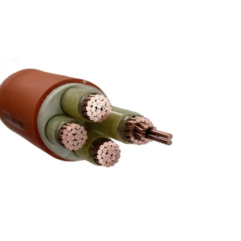
The overlap between cable types is most visible here. Topsides power distribution — motor control centres, lighting panels, HVAC — uses armored cables rated to IEC 60092 (marine and offshore) with appropriate flame-retardant sheaths. Safety-critical circuits (fire and gas detection, emergency shutdown, deluge control) require fire-resistant armored control cables tested to IEC 60331, maintaining circuit integrity at temperatures up to 750°C or 950°C depending on the specified duration. A single platform specification will typically call for both families across perhaps 40–60 distinct cable types. Confusing a standard armored instrumentation cable with a fire-resistant variant on an ESD loop is not a paperwork problem — it is a life-safety problem.
Mining and Tunneling
Moving equipment — continuous miners, shuttle cars, longwall shearers — uses trailing cables built to IEC 60245 or national mining standards, designed to flex repeatedly without insulation fatigue. Fixed runs in hazardous zones (Zone 1, Zone 2, or equivalent) require armored cables certified for the area classification, often with additional anti-static or flame-retardant outer sheaths per IEC 60502 and local mining regulations. The hazardous-area certification matters more than the armor type in these environments.
Building Services: Airports, Data Centers, Hospitals
LSZH (low-smoke zero-halogen) armored cables handle the power distribution side in occupied buildings where toxic combustion gases pose an evacuation risk. Screened control cables serve BMS, fire alarm loop wiring, and access-control systems — usually 300/500 V rated, LSZH sheathed, with overall screen and drain wire. Data centers in particular tend to over-specify armor on BMS cabling, adding unnecessary weight and bend-radius constraints in cable management trays already running near capacity.
Renewable Energy: Wind and Solar
In wind farms, the turbine-to-collection-substation MV runs are armored XLPE cables, often direct-buried with sand bedding. Inside the tower, flexible unarmored cables handle the dynamic section near the nacelle. Solar PV string cables (DC, often 1.5 kV or 1.8 kV rated per IEC 62930) need UV-stable outer sheaths and single-core construction; screened control cables connect inverter communication, monitoring strings, and SCADA field devices. UV degradation on the outer sheath is a real field problem in high-irradiance sites — a cable specified without checking UV stabilizer additive levels can show sheath cracking within three to five years in desert or high-altitude installations.
Fire-resistant armored control cables tested to IEC 60331 maintain circuit integrity at specified temperatures, making them mandatory for safety-critical circuits on offshore platforms and in buildings where standard armored cables would fail during a fire event.True
IEC 60331 specifies a fire resistance test where cables must continue to function under flame and mechanical shock conditions at defined temperatures and durations. Standard armored cables without the fire-resistant insulation and sheath system do not meet this requirement and are not a safe substitute on ESD, fire alarm, or deluge loops.
| Application | Recommended Cable Family | Key Standard | Typical Voltage Rating | Armor Required |
|---|---|---|---|---|
| LV power distribution (motor feeders, switchgear) | Multi-core armored power cable (XLPE/SWA) | IEC 60502-1 | 0.6/1 kV | Yes |
| MV distribution (substation feeders) | Single/multi-core armored MV cable | IEC 60502-2 | 3.8/6.6 kV – 19/33 kV | Yes |
| PLC I/O, 4–20 mA instrumentation | Multi-core screened control cable | IEC 60227 / IEC 60228 | 300/500 V or 450/750 V | Usually No |
| Offshore safety-critical (ESD, F&G) | Fire-resistant armored control cable | IEC 60331 / IEC 60092 | 450/750 V | Yes |
| Mining fixed runs (hazardous zone) | Armored, zone-certified power/control | IEC 60502 / IEC 60245 | 0.6/1 kV | Yes |
| Mining trailing (moving equipment) | Flexible trailing cable | IEC 60245 | 0.6/1 kV | No (flexible armor variants exist) |
| BMS / fire alarm (buildings) | LSZH screened control cable | IEC 60227 / local building code | 300/500 V | Application-dependent |
| Building power (hospital, airport) | LSZH armored power cable | IEC 60502-1 | 0.6/1 kV | Yes |
| Solar PV string runs | Single-core UV-stable DC cable | IEC 62930 | 1.5 kV DC | No (for flexible rooftop runs) |
| Wind farm collection circuits | Armored MV XLPE cable | IEC 60502-2 | 6.6/33 kV | Yes |
| SCADA / inverter comms (renewables) | Screened multi-core control cable | IEC 60227 | 300/500 V | No |
Installation Rules, Segregation Requirements, and Common Site Mistakes
Segregation between power and control/instrumentation cables is one of those rules that gets dismissed on tight job sites — until a commissioning engineer spends three days chasing intermittent faults in a PLC analog loop that trace back to a cable tray decision made six weeks earlier during rough-in.
The Segregation Rule and Why 200 mm Is a Floor, Not a Target
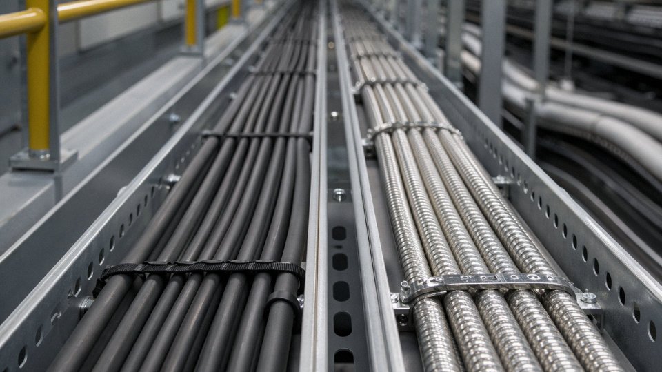
IEC 61000-5-2 guidance sets 200 mm as the minimum separation between power cables and unscreened instrumentation or control cables running in parallel. In practice, most experienced plant engineers treat that as the absolute minimum for short parallel runs under 5 meters or so, and push toward 300–500 mm on longer runs, particularly when the power cables are carrying variable-frequency drive outputs. VFD cables are far nastier than simple 50 Hz feeders because they generate high-frequency switching transients that travel considerably further.
Where trays must cross, cross at 90°. Not 45°, not “roughly perpendicular.” The 90° rule minimizes the length of mutual coupling, which is the actual physics driving the interference. A diagonal crossing at 45° can double the effective coupled length compared to a proper right-angle crossing.
The Induced Voltage Problem Is Smaller Than You Think — and Still Enough to Break Your Loop
A 0.6/1 kV armored power cable carrying a modest load current, running parallel to an unscreened 0.5 mm² control cable for even 10–15 meters, can induce millivolt-level noise into that control conductor. That sounds trivial. A 4–20 mA signal representing a 0–100°C temperature span has a resolution of roughly 160 µA per degree; a few millivolts of induced noise across a typical loop impedance can translate directly into a false reading of 1–3°C, which is entirely sufficient to cause nuisance trips on a tightly controlled process or — worse — mask a genuine deviation that should have triggered an alarm.
Screening helps but only if the screen is actually earthed. Drain wire left floating is extremely common on site. It accomplishes nothing.
Running a screened control cable parallel to a power cable eliminates EMI risk regardless of separation distance.False
Screening reduces capacitively coupled interference significantly, but inductive coupling still depends on physical separation and parallel run length. A floating or poorly earthed screen can actually act as an antenna, making interference worse than an unscreened cable with proper separation.
Bend Radius: A Number People Know and Routinely Ignore
IEC 60502-1 specifies a minimum installation bend radius of 6× OD for multicore armored cables. Screened control cables are tighter to work with — manufacturers typically specify 8–12× OD, depending on the screen type and whether the cable has a foil or braid. Pulling an armored cable around a 90° conduit elbow in a congested cable basement without checking the OD first is genuinely one of the most common ways to crack armor wires and damage insulation simultaneously, and you won’t necessarily see it at the initial megger test. The damage shows up six months later when water ingress causes insulation resistance to drift.
Gland Selection Is Not Interchangeable
SWA cables require earthed steel cable glands with armor clamp rings — a proper A2 or CW-type gland in common British/IEC practice, sized to grip the armor wires firmly. Using a standard PVC cable gland on an armored cable because it was the only size in the stores is a real-world failure mode. It voids the IP rating at the entry point, and it leaves the armor unearthed. On a gland that will carry the armor’s fault current path during a ground fault, that matters.
Control cable glands, by contrast, need to pick up the screen drain wire and earth it reliably. A gland that compresses the outer sheath but leaves the drain wire kinked and barely touching the backnut is not a landed screen. Check continuity of screen earth at every termination, not just the panel end.
Armor Earthing: Both Ends Versus Single End
Standard practice is to earth SWA armor at both ends. This provides the lowest impedance fault current return path and is correct for most power distribution cables up to several hundred meters. On long armored signal cable runs — say, over 200 meters in a facility with multiple earthing points at different ground potential — earthing both ends creates a circulating current loop through the armor. The resulting current induces its own magnetic field, which ironically can degrade the signal integrity the armor was meant to protect. Single-end earthing at the source end breaks the circulating current path. It sacrifices some fault-current return capacity but is the correct choice for long instrumentation runs where both-ends earthing creates ground loop problems.
Five Mistakes That Show Up Repeatedly
Using armored cable glands on unarmored cable is probably the most common — it happens when cables get substituted late in a project and glands aren’t re-ordered. The armor clamp ring grips nothing, the IP rating fails, and nobody notices until a water ingress fault six months into operation.
Exceeding bend radius during installation, as covered above. Inadequate support spacing — armored multicore cable is heavy, and clamps spaced at 1.5 meters instead of the required 0.8–1.0 meters (depending on cable weight and tray type) causes sagging that stresses the cable at each support point progressively over time.
Omitting drain wire earthing on screened control cables happens constantly on large panels where termination is rushed at the end of a project. And mislabeling cores in multi-core control cables — or not labeling them at all, relying on the “the installer will remember” assumption — creates commissioning nightmares and genuine safety risk when cables are disturbed during maintenance years later. Number every core at both ends. Use heat-shrink ferrules, not tape flags that fall off in a warm panel.
Procurement Checklist: Specifications, Testing Evidence, and What to Demand from Your Cable Supplier
Getting the specification right on paper means nothing if the cable delivered to site doesn’t match what was tested and certified. This is where procurement discipline separates projects that run smoothly from those that end up with a contested shipment sitting in a bonded warehouse while the installation schedule slips.
Mandatory Documentation — Don’t Accept Substitutes
Every purchase order for control or armored cable should require, as a minimum, the following before goods ship:
Conductor material certificate confirming copper purity ≥ 99.9% (electrolytic-grade). This matters because sub-grade copper — common in spot-market bargain buys — raises resistivity, creates termination problems over time, and can void UL or IEC compliance claims outright.
Insulation compound test report from the cable manufacturer’s own QC lab, specifying compound grade, tensile strength, elongation at break, and aging test results. For PVC insulation on control cables, you want elongation typically above 150% post-aging; for XLPE on armored power cables, the aging retention figures should be documented explicitly, not just referenced by compound trade name.
Drum test certificates per IEC 60502-1 (armored power cables) or IEC 60227 (control cables rated 300/500 V and 450/750 V) as applicable, issued per production drum. Batch-level certificates covering a notional range of drums are not the same thing and shouldn’t be accepted as equivalent.
Third-party type test reports from an accredited laboratory — CESI, KEMA, SGS, or equivalent national body. Type tests are expensive, so a manufacturer who has genuinely done them will have the reports readily available. If a supplier takes more than a day to produce a type test report, that’s a sign worth noting.
Drum Length, Marking, and How to Verify What You’re Actually Getting
Standard export drum lengths for armored cable run roughly 500 m to 1,000 m per drum depending on conductor cross-section; larger sizes (95 mm² and above) typically come in shorter lengths, 200–500 m, simply due to weight constraints. Control cable drums are more flexible — 500 m to 2,000 m is common for smaller multi-core types.
What matters operationally: the cable sheath should carry sequential meter markings printed at every 1 m interval. When a shipment arrives, pull the outer wrapping and physically check the start and end meter marks against the invoice quantity. It takes ten minutes and has caught short-shipments of 3–8% more times than it should have needed to. Jinda marks every meter on the sheath as standard practice, and the drum card details the exact measured length at the time of despatch.
Factory Acceptance Testing Parameters
For armored cables, a credible FAT protocol covers conductor continuity on every core, insulation resistance (IR) testing — minimum 1,000 MΩ·km at 20°C is a reasonable floor, though actual values for well-made XLPE cables are often an order of magnitude higher — and a high-voltage withstand test at 3.5 kV AC for 5 minutes on 1 kV-rated cables. Armor continuity end-to-end is frequently skipped by less diligent suppliers and is worth calling out explicitly in your purchase specification.
For screened control and instrumentation cables, FAT should extend to capacitance balance testing between pairs (unbalance typically held to ≤ 1.5 pF/m on precision instrumentation types), transfer impedance for high-performance shielded cables where the application involves sensitive signal circuits, and cross-talk attenuation on multi-pair designs. These parameters don’t show up on a basic test certificate — you have to ask for them specifically.
Jinda issues per-drum IEC test certificates and can provide third-party type test reports from accredited laboratories including SGS for export orders.True
Manufacturers with genuine export experience maintain current third-party type test documentation as routine. Requiring this on your PO protects against substitution mid-contract.
Lead Times — What’s Realistic
Standard stocked sizes — think 4-core 2.5 mm² SWA or 12-core 1.5 mm² control cable — can typically ship within 2–4 weeks from Jinda’s warehouse inventory. Custom configurations are a different story. A 37-pair individually screened instrumentation cable with an overall braid plus fire-resistant barrier sheath will realistically need 6–10 weeks production lead time, sometimes longer during Q4 when raw copper prices spike and mill lead times stretch. Build that into your project schedule; it’s a number that consistently catches EPC procurement teams off guard.
What Jinda Brings to International Projects
Five production bases, 470,000 m² of manufacturing space, and over 35 years exporting to more than 50 countries means Jinda carries the production capacity and documentation infrastructure that serious international EPC projects require — not just the ability to manufacture, but the systems to support pre-shipment inspection, third-party witness testing, and post-delivery technical queries when an installation question comes up at 2 a.m. on a commissioning schedule. In-house R&D enables non-standard designs — special shielding geometries, hybrid constructions, unusual voltage ratings — without farming the development out, which keeps both lead time and quality control under one roof.
Frequently Asked Questions About Control Cables and Armored Cables
Can I use an armored cable instead of a control cable for PLC wiring?
Generally, no — and this substitution causes real problems on site. Armored power cables are built around a small number of large conductors optimized for current-carrying, not multi-core signal routing. A typical SWA cable gives you two, three, or four cores. A PLC I/O cabinet might need 12, 24, or 37 individually identified cores running to a marshalling panel. Stuffing that wiring with armored cable means you either run a dozen separate cables where three screened control cables would do the job, or you buy a multicore armored cable not designed for the voltage class and shielding requirements of analog 4–20 mA loops. The steel armor also adds rigid bulk inside a control panel, where bend radius constraints are already tight. Most armored cables don’t carry individual core colors or number markers past 5 or 7 cores without custom ordering. For PLC wiring, specify a screened multicore control cable — foil or braid shielded, IEC 60228 Class 5 conductors, proper core identification — not an armored cable.
Can a control cable be armored?
Yes, absolutely. Armored control cables are a well-established product category, not some exotic hybrid. When you’re running a 12-core or 24-core control cable across an outdoor cable tray exposed to construction traffic, or direct-burying it in a trench where rodents or accidental excavation are realistic hazards, you want the SWA or steel tape armor (STA) layer over the multi-core bundle. Jinda manufactures armored control cables to IEC 60502 and GB/T 9330, combining proper core numbering, individual insulation, and optional collective screening with a full armoring layer. The voltage rating stays at the control level — 450/750 V typically — but the mechanical protection is real. Don’t assume “armored” and “control” are mutually exclusive categories.
What is the difference between screened and armored?
These two terms get conflated constantly, and the confusion causes specification errors. Screening — whether aluminum-polyester foil or tinned copper braid — is an electrical function. It attenuates electromagnetic interference coupling into signal conductors, and it provides a defined ground reference for the shield drain wire. Armoring is purely mechanical: it resists crush loads, tensile pull, and rodent damage. A cable can have screening without armoring (most panel control cables), armoring without screening (standard SWA power cable), or both (an armored instrumentation cable for a field instrument in a high-EMI environment with direct burial). Specify both when the application genuinely demands both. Paying for armor when you only have an EMI problem wastes money; relying on foil screening to stop a backhoe is worse.
Armored cable armor layers provide electromagnetic shielding equivalent to a dedicated foil or braid screen.False
Steel wire armoring offers negligible EMI attenuation at signal frequencies. Armoring is a mechanical layer; EMI shielding requires a dedicated foil or braid screen with a continuous drain wire connected to ground.
How do I identify an armored cable on site without a datasheet?
Run your hand along it. Armored cable feels rigid and corrugated or has a perceptible wire-wound texture under the outer sheath — you can often feel individual wires or the tape ridges through a thin PVC jacket. Try to bend a short section by hand: an SWA cable in 16 mm² or larger will resist firmly; a 4 mm² SWA still bends noticeably stiffer than an equivalent unarmored cable. Unarmored cables flex with almost no resistance. If you have a knife handy and can nick the outer sheath safely, the metallic layer is immediately visible. On a tight site where cables have lost their drum labels — which happens more often than anyone admits — this tactile check is usually enough to sort armored from unarmored before you cut.
Is SWA cable suitable for use in explosive atmospheres?
SWA cable itself carries no intrinsic safety rating. The cable is a component, not a certified system. In ATEX or IECEx Zone 1 and Zone 2 installations, SWA cable is routinely used, but the complete circuit must be certified: appropriate Ex-rated cable glands (the gland clamping the armor is part of the fault-current path), certified Zener diode barriers or galvanic isolators for intrinsically safe circuits, and equipment with the correct zone rating. Using SWA cable alone doesn’t make a circuit explosion-safe. If you’re specifying for a hazardous area, the cable selection is maybe 20% of the compliance picture — the gland, the barrier, and the installation drawing review matter just as much.
What conductor class should I specify for a repeatedly flexed control cable?
IEC 60228 Class 2 — the standard stranded or solid conductor used in most fixed-installation control cables — will fatigue and crack if it’s being flexed continuously, say on a drag chain or a robot arm. For any application with repeated movement, specify Class 5 (flexible stranded, typically 16–50 individual wires per conductor depending on cross-section) as a minimum, or Class 6 (extra-flexible, finer stranding still) for severe flexing duty. The difference in price is modest; the difference in service life on a drag chain application can be the gap between two years and ten. Ask the manufacturer for flexing cycle endurance test data — a credible supplier will have it.
How does Jinda support customers selecting between cable types for large projects?
Jinda’s technical team works through cable selection before a purchase order is placed — reviewing single-line drawings, installation route descriptions, environmental ratings, and applicable standards to confirm the right construction for each circuit type. Free samples of candidate cable constructions are available for larger projects so your installation team can check flexibility, gland compatibility, and core identification before committing to full quantities. Project-specific datasheets, factory test reports, and third-party certification documents are available on request. For export projects, Jinda can supply cables tested to IEC, BS, or other international standards depending on the destination market’s requirements.