
Specify the wrong cable type on a bill of materials and you will find out about it the hard way — usually during commissioning, sometimes mid-production. A control cable pulled into a power tray starts picking up interference that sends your PLC inputs haywire; an undersized power cable runs hot, degrades insulation over months, and eventually trips a breaker at the worst possible moment. The rework costs alone — pulling, re-routing, re-terminating — routinely run to multiples of what the correct cable would have cost at procurement. Getting the classification right from the start is the only practical fix.
The three main types of cables are power cables, control cables, and communication (signal) cables. Power cables carry electrical energy to equipment and infrastructure, typically from 1 kV up to 500 kV with conductor cross-sections from 1.5 mm² to 2,500 mm² depending on load. Control cables manage switching and instrumentation signals at low voltages, usually with conductors of 0.5–10 mm². Communication cables transmit data and analog signals where shielding and impedance characteristics matter more than current-carrying capacity.
What makes this more than a textbook classification is that real installations routinely mix all three — sometimes in the same conduit run, sometimes with the same outer diameter, which is where procurement errors breed. Each type carries different construction standards, derating rules, and failure modes, and understanding where those lines fall changes how you specify, how you buy, and how you troubleshoot when something goes wrong.
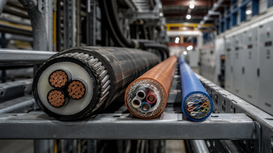
Power Cables Dissected: Conductor Materials, Insulation Grades, and Voltage Classifications
Power cables carry the highest electrical stress of any cable type on site, and the consequences of a wrong specification aren’t a nuisance — they’re a transformer fire, a months-long insurance claim, or a wind farm feeder that fails during its first thermal cycling season. Getting the construction right starts with understanding what each layer actually does.
Anatomy of a Power Cable, Layer by Layer
The conductor sits at the center: copper or aluminum, solid or stranded. Copper’s conductivity runs roughly 58 MS/m versus aluminum’s ~35 MS/m, which means an aluminum conductor needs about 1.6× the cross-section to carry the same current. Aluminum saves significant weight and cost on long runs — on a 10 km underground distribution feeder, that matters enormously — but it work-hardens at terminations and requires proper compression lugs and anti-oxidant compound. Skipping that step in the field is one of the most common causes of joint failures I’ve seen on industrial sites. Stranded conductors (IEC 60228 Class 2 for fixed installation, Class 5 for flexible service) are used almost universally above roughly 16 mm² because bending a solid bar that thick without cracking it is impractical.
Wrapped around the conductor is the conductor screen — a semi-conductive layer that smooths the electrical field gradient. Without it, the sharp surface irregularities of a stranded conductor concentrate charge and initiate treeing in the insulation. It’s a thin layer, easy to overlook, but it’s doing real electrochemical work.
The insulation is where the voltage is actually held. XLPE (cross-linked polyethylene) dominates modern medium- and high-voltage cable production for good reason: continuous thermal rating of 90°C, short-circuit tolerance up to around 250°C, excellent dielectric strength, and low moisture absorption. PVC insulation, rated 70°C continuous, is cheaper and easier to process but noticeably inferior on all those fronts. On a 33 kV feeder running at high load factor, the 20°C thermal headroom difference between PVC and XLPE translates directly into ampacity — the cable either runs safely derated or you buy a larger cross-section. EPR (ethylene propylene rubber) is the other serious option: slightly lower dielectric strength than XLPE but genuinely superior flexibility at low temperatures and better resistance to UV and ozone, which is why it shows up frequently in offshore and mining environments.
Outside the insulation sits an insulation screen (another semi-conductive layer), then typically a metallic sheath — either copper tape, lead alloy, or corrugated aluminum — to carry fault current and provide a ground reference. Armor comes next, chosen by installation method. Steel wire armor (SWA) handles tensile loads in direct burial and vertical runs; steel tape armor (STA) is lighter and adequate for protected duct or tray work; aluminum wire armor (AWA) is specified where stray DC currents are a concern, as steel armor in DC environments can experience magnetic losses and heating.
Voltage Classifications and Where They Land in Practice
Low voltage (≤1 kV, governed by IEC 60502-1) covers most industrial plant distribution, machinery feeds, and building power — the bread-and-butter of any electrical BOM. Medium voltage (roughly 1–35 kV, IEC 60502-2) handles primary distribution within industrial facilities, wind farm collector systems, and urban ring main networks. High voltage (35–220 kV) is substation interconnection and regional grid work. Ultra-high voltage, 220–500 kV and above, is bulk transmission and submarine export cables for large offshore wind projects; construction at that level involves specialized factory qualification and testing that most cable plants simply don’t hold.
XLPE-insulated power cables rated 90°C continuous have higher ampacity than PVC-insulated cables of the same cross-section and installation conditions.True
Ampacity calculation per IEC 60287 is directly dependent on the maximum permissible conductor temperature. XLPE's 90°C rating versus PVC's 70°C limit means XLPE cables carry more current for the same conductor size under identical installation conditions.
Conductor Cross-Section vs. Current-Carrying Capacity
Figures below are indicative ranges per IEC 60287 principles for 0.6/1 kV single-core XLPE cable; actual values shift with grouping, ground thermal resistivity (typically 1.0–2.5 K·m/W depending on soil type and moisture), and ambient temperature.
| Conductor Cross-Section | Copper — In Ground (A) | Copper — In Air (A) | Aluminum — In Ground (A) | Aluminum — In Air (A) |
|---|---|---|---|---|
| 16 mm² | 105–115 | 110–125 | 80–90 | 85–95 |
| 50 mm² | 175–195 | 195–220 | 135–150 | 150–170 |
| 95 mm² | 250–275 | 285–315 | 195–215 | 220–245 |
| 185 mm² | 355–390 | 415–460 | 275–305 | 320–355 |
| 400 mm² | 490–540 | 590–650 | 380–420 | 455–505 |
| 630 mm² | 600–660 | 740–820 | 465–515 | 570–635 |
Treat these as planning figures. Before committing conductor size on a real project, run a full IEC 60287 calculation with your actual soil report and cable routing details — a derating factor of 0.7–0.8 for grouped cables in a congested duct bank is not unusual, and ignoring it is how you end up thermally overloading a newly commissioned feeder.
Control Cables Explained: Signal Integrity, Multi-Core Configurations, and Shielding Logic
Control cables are not power cables with smaller conductors. That distinction matters more than most procurement specs acknowledge. Where power cables move bulk energy — kilowatts, megawatts, hundreds of amps — control cables carry commands: a 4–20 mA signal telling a valve to open 40%, a discrete 24 V DC pulse confirming a conveyor has reached speed, a fieldbus packet updating a PLC scan 50 times per second. Voltages rarely exceed 690 V AC and are usually far lower; current draw is milliamps to single-digit amps. The design priority shifts entirely from thermal ampacity to signal fidelity.
Mixing up these categories in a BOM is one of those specification errors that rarely shows up until commissioning — when the control room starts seeing ghost trips and noisy analog readings, and nobody can figure out why.
Core Count and I/O Density
Industrial automation projects spec control cables from 2-core all the way to 37-core, 61-core, or beyond, depending on I/O point density and how the system designer has bundled signals. A small local panel might need a 4-core or 7-core run. A distributed control system junction box on a large refinery — pulling together dozens of field instruments back to a marshalling cabinet — might justify a 24-core or 37-core cable to avoid running parallel singles across a cable tray that’s already overloaded.
Conductor sizes in practice: 0.75 mm² for light signal and indicator circuits, 1.0 mm² and 1.5 mm² for the bulk of PLC I/O wiring, 2.5 mm² when the cable also carries control power to solenoids or small actuators. The choice depends on loop resistance requirements, allowable voltage drop over the cable run, and whether the circuit carries any meaningful switched current. For runs over roughly 200–300 m with sensitive analog signals, even 1.5 mm² can start to look marginal — worth checking against the transmitter’s specified load resistance.
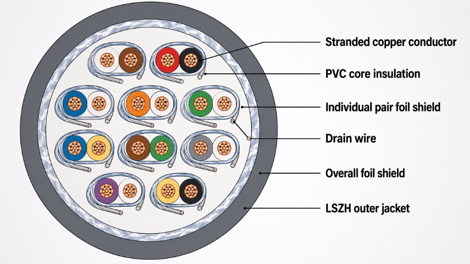
Shielding Architectures and When They Actually Matter
Three shielding configurations show up repeatedly in industrial specs, and they are not interchangeable.
An overall aluminum-polyester foil shield with drain wire gives decent general-purpose EMI attenuation at low cost. It’s the standard for most instrumentation and control runs in moderate-noise environments — typical process plants, building automation, light manufacturing. The drain wire (usually bare tinned copper, 0.5–1.0 mm²) is your grounding path; leave it floating at one end to avoid ground loops on analog circuits.
Individual pair or triad shielding (each signal pair wrapped separately, plus an overall shield) is the right call when you’re running multiple analog signals in a single cable and crosstalk between channels is a concern. Think thermocouple extension cables or multi-loop 4–20 mA in the same jacket. Each pair shield is grounded independently.
Braided copper shield offers superior mechanical durability and better high-frequency attenuation than foil alone — relevant on offshore platforms, inside electrical cabinets with VFD-heavy environments, or anywhere the cable is subject to physical flexing. The trade-off is cost and diameter.
Using an unshielded control cable in a high-EMI industrial environment — near VFDs, large motors, or induction furnaces — can cause analog signal drift, spurious digital trips, and PLC communication errors.True
Electromagnetic interference couples into unshielded conductors as common-mode and differential-mode noise. In 4–20 mA loops this can appear as signal offset or instability; in discrete circuits it can exceed logic threshold margins and cause false state changes. Shielded cables with proper single-point grounding are standard engineering practice in IEC and ISA instrumentation design for exactly this reason.
A steel mill or an arc furnace bay is not the place to find this out the hard way. EMI in those environments is severe enough that even foil-shielded cable benefits from running in grounded steel conduit.
Insulation and Jacket Materials
PVC insulation per IEC 60227 covers the majority of general-purpose control cable applications — cost-effective, well-understood, adequate for operating temperatures from roughly -15°C to +70°C depending on formulation. For cold-store facilities or outdoor Nordic installations where cables see -40°C, you need a cold-flexible compound; standard PVC goes brittle and cracks around terminals.
LSZH (Low Smoke Zero Halogen) jackets, tested per IEC 61034 (smoke density) and IEC 60754 (halogen content), are specified for tunnels, subway stations, offshore accommodations, and enclosed machinery spaces — anywhere that HCl fumes from burning PVC would be a secondary hazard. The cost premium over standard PVC is usually 20–40%, depending on cable size and supplier.
Petrochemical plants add another layer of requirements: oil-resistant outer jackets (HOFR, or specific polyurethane and CSP compounds), flame-retardant or FPE insulation, and sometimes individual armoring where cables pass through areas with mechanical hazard.
Reading the Type Designation
IEC 60228 sets conductor construction standards (Class 1 solid, Class 2 stranded, Class 5 fine-stranded) that appear in the cable designation. EN 50525 is the harmonized European framework covering many control cable types. A designation like LIYY 12×0.75 breaks down as: LI = instrumentation cable, YY = PVC insulation and PVC outer jacket, 12 cores, 0.75 mm² each. Add an S and you have an overall screen. An H at the start signals harmonized type per EN 50525. Manufacturer datasheets vary in notation, but the core count × conductor cross-section format is consistent — if a datasheet doesn’t show the relevant IEC standard number alongside the type code, that’s worth querying before you commit to a large order.
Communication and Data Cables: Structured Cabling, Instrumentation Lines, and Fiber Optic Fundamentals
The communication cable family is where specifications get messy fast. Unlike power cables, where the dominant variables are voltage class and conductor cross-section, communication cables split into at least three technically distinct sub-families — each with its own physics, standards stack, and failure modes. Getting them mixed up on a project isn’t a theoretical risk; it shows up as unexplained signal dropouts, ground loop interference on a 4–20 mA loop at 2 a.m., or a fiber backbone that maxes out at 300 m when the data sheet promised 550.
Analog Instrumentation Cables: 4–20 mA, Thermocouples, and RTDs
These cables carry low-level analog signals — typically 4–20 mA current loops, millivolt-range thermocouple signals, or the small resistance changes an RTD produces. The currents are tiny. That means any capacitive or inductive pickup from adjacent power wiring translates directly into measurement error, which is why individually shielded pairs with a dedicated drain wire are the standard construction for instrumentation cable, not an optional upgrade.
Thermocouple extension cables are a specific sub-type that procurement often gets wrong. They must be made from alloy conductors that match (or are compatible with) the thermocouple type — using standard copper conductors to extend a Type K thermocouple introduces a parasitic junction and corrupts the reading. Operating temperature range for the cable itself matters here too: instrumentation cables generally handle –40°C to roughly +90°C depending on insulation, but cables routed near furnaces or heat exchangers need to be specced accordingly, not just grabbed off the shelf because the cross-section looks right.
Twisted-Pair Data Cables: Why the Twist Rate Actually Matters
The physical reason twisted pairs work is straightforward enough — by twisting two conductors together, any external electromagnetic field induces nearly equal and opposite voltages in adjacent half-twists, which cancel at the receiver. The tighter the twist rate (more twists per meter), the better the cancellation at higher frequencies, which is why Cat 6A has a significantly tighter twist rate than Cat 5e. Near-end crosstalk (NEXT) performance is the direct measurable result of this geometry, and ANSI/TIA-568 sets minimum NEXT values for each Category rating.
In practice, Cat 5e handles 1 Gb/s out to 100 m and is still entirely adequate for most building automation and light industrial Ethernet. Cat 6 improves headroom for 1 Gb/s and supports 10 Gb/s up to roughly 55 m. Cat 6A extends 10 Gb/s to the full 100 m channel — useful in data centers and increasingly in industrial settings running time-sensitive networking (TSN) protocols. The cost difference between Cat 5e and Cat 6A bulk cable isn’t enormous per meter, but across a large plant installation with hundreds of drops, it adds up, so specifying Cat 6A everywhere “just in case” needs an actual justification.
Unshielded Cat 5e cable is sufficient for most standard industrial Ethernet applications up to 100 m at 1 Gb/s when routed away from high-current power conductors.True
ANSI/TIA-568 confirms Cat 5e supports 1000BASE-T at 100 m channel length; the caveat is EMI separation from power cables, which is an installation practice issue, not a cable specification issue.
Single-Mode vs. Multimode Fiber: The Distance and Cost Equation
Single-mode fiber (9 µm core) works by allowing only one propagation mode — this eliminates modal dispersion and lets it run distances of 10 km, 40 km, or longer depending on transceiver quality and wavelength (1310 nm or 1550 nm windows). Multimode fiber (50 µm or 62.5 µm core) supports multiple propagation modes and uses cheaper 850 nm VCSELs, but modal dispersion limits reach — typically 300–550 m at 1 Gb/s for OM3/OM4 grades, less on older 62.5 µm cable.
For plant-floor backbone runs under 300 m, multimode OM3 or OM4 is usually the economical choice because the transceivers cost significantly less than single-mode equivalents. Once you’re running fiber between buildings, across a campus, or connecting substations kilometers apart, single-mode becomes the only sensible option regardless of up-front transceiver cost. The fiber itself is similarly priced; you’re paying for the optics.
IEC 60794 governs fiber optic cable construction broadly, while ITU-T G.652 covers standard single-mode fiber and G.657 covers bend-insensitive single-mode variants — relevant wherever cables route through tight conduit bends or junction boxes. For gel-filled, water-blocked cables used in direct-burial or underground conduit applications, look for this construction explicitly in the spec sheet; not all outdoor-rated fiber includes it.
Industrial Fieldbus Cables: Not Just “Any Shielded Cable”
PROFIBUS PA, DeviceNet, and Foundation Fieldbus cables have specific electrical characteristics that are non-negotiable. PROFIBUS PA, for instance, requires cable with a characteristic impedance of around 150 Ω, capacitance below roughly 100 pF/m, and a defined loop resistance — use a generic screened instrumentation cable and you’ll see reflections and communication errors that are genuinely difficult to diagnose without a fieldbus analyzer. DeviceNet specifies thick and thin cable variants with defined impedance and color coding. These aren’t marketing distinctions; the bus protocol depends on the cable’s electrical characteristics to terminate correctly and maintain signal integrity across multiple nodes.
Always cross-reference the fieldbus supplier’s cable specification against what’s being purchased. Generic “instrumentation cable” is not a substitute, even if the dimensions look similar.
Material Science Behind Cable Performance: Copper vs. Aluminum, Insulation Compounds, and Jacket Chemistry
The catalog says “XLPE insulated, copper conductor, 11 kV.” That tells you almost nothing about whether the cable will still perform at year 15 in a coastal substation or a chemical plant tunnel. The real decisions live in the material science underneath those labels.
Copper vs. Aluminum: Six Dimensions That Actually Matter
Copper’s conductivity runs around 58 MS/m; aluminum sits near 35 MS/m. That gap means an aluminum conductor needs roughly 1.6× the cross-section to carry the same current, which directly affects conduit fill calculations and termination hardware sizing. On a large-scale solar farm or grid feeder run, that extra cross-section often still pencils out because aluminum runs 3–4× cheaper per kilogram than copper on spot markets — and that ratio has held through most commodity cycles, though both metals swing hard with global demand.
Weight matters more than engineers admit until they’re pulling cable through an overhead cable tray on a refinery expansion. Aluminum is roughly one-third the density of copper, so a 240 mm² aluminum feeder is dramatically easier to handle than its copper equivalent, which affects both installation labor and structural loading on tray systems.
Where aluminum falls down is jointing. Aluminum oxidizes quickly, forming Al₂O₃ — an electrically resistive layer — right at the connection surface. Bi-metallic lugs, oxide-inhibiting compound (Penetrox or equivalent), and correct torque sequences are non-negotiable, not optional. Skip any of those steps and you’ll be chasing a hot joint within a year or two. Copper is more forgiving, which is why it stays dominant in control panels, motor circuits, and any installation where connection quality is hard to inspect afterward.
Thermal expansion coefficient differences — aluminum expands roughly 23 µm/m·°C versus copper’s 17 µm/m·°C — matter most in medium-voltage cable terminations subject to cyclic loading. Aluminum also suffers more in marine or coastal environments where chloride-accelerated corrosion attacks unprotected conductor strands at exposed ends.
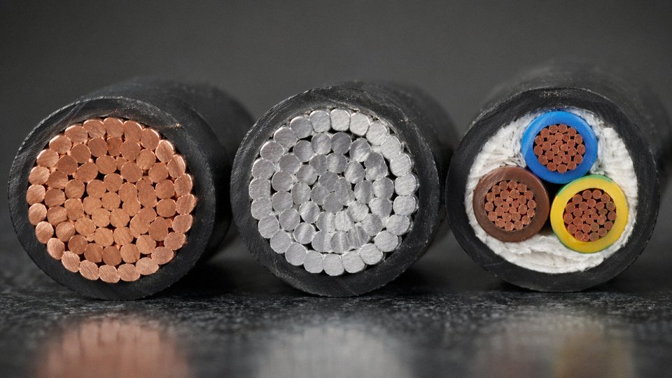
Rough decision logic: use aluminum for MV/HV power feeders above roughly 95 mm² where runs are long, accessible, and jointed by trained electricians. Stick with copper for control, instrumentation, short motor circuits, and anywhere jointing quality is difficult to guarantee.
Insulation: XLPE, PVC, LSZH, and EPR
Standard PVC insulation is thermally rated to 70°C conductor temperature. That sounds adequate until you factor in ambient temperature, bundling derating, and load growth over a 30-year cable life. Cross-linked polyethylene (XLPE) changes the game. During vulcanization — typically using organic peroxides in a continuous caterpillar CV tube at controlled temperature and pressure, or alternatively through silane moisture-cure processes for smaller-diameter cables — covalent bonds form between polymer chains, creating a three-dimensional network. The result raises continuous operating temperature to 90°C, improves resistance to moisture ingress, and substantially reduces long-term dielectric losses at medium and high voltage. XLPE is the default choice for anything above 1 kV in most modern specifications, and the performance gap versus PVC widens with voltage class.
XLPE insulation raises the continuous operating temperature ceiling from 70°C (PVC) to 90°C and significantly improves moisture resistance through its cross-linked polymer network.True
Cross-linking creates covalent bonds between PE polymer chains during vulcanization, eliminating the thermoplastic flow behavior that limits PVC's thermal ceiling and improving both moisture and chemical resistance — consistent with IEC 60502 and IEEE 1202 performance data.
LSZH compounds work differently. Instead of cross-linking for thermal performance, they incorporate mineral fillers — primarily aluminum trihydrate (ATH) and magnesium hydroxide (MDH) — at high loading levels, sometimes 60% or more by weight. Under flame, these fillers decompose endothermically, releasing water vapor that dilutes combustible gases and cools the flame front. No chlorine, no HBr, no HCl acid gas clouds that destroy electronics and injure people evacuating a tunnel or metro station. IEC 60332-3 fire propagation testing is the standard reference point for specifying LSZH cables in grouped installations. The trade-off is mechanical stiffness at low temperatures and slightly lower tensile strength — something to check if the cable runs through tight bends in cold environments.
EPR (ethylene propylene rubber) insulation is worth specifying when you need genuine flexibility at -40°C combined with medium-voltage electrical stress tolerance. It’s standard in mining draglines, shipboard power circuits, and portable equipment — anywhere the cable flexes repeatedly or sits in low-temperature outdoor service. EPR has excellent partial-discharge resistance and handles high electrical stress gradients better than most thermoplastic insulations, which is why it appears in 6.6 kV and 11 kV mining cables regularly.
Jacket and Sheath Materials: The Outer Defense Layer
The outer jacket takes all the mechanical and chemical abuse the insulation never should. Lead sheaths — still found in legacy HV transmission cables and some specialist telecom infrastructure — offer an almost impermeable moisture barrier and were the standard for underground cables for decades. Environmental regulations, particularly RoHS and various national chemical control frameworks, have pushed lead into increasingly restricted territory. Expect scrutiny on any new specification that calls for it.
Aluminum sheaths, corrugated or smooth, are the modern HV cable standard. Corrugation adds flexibility without sacrificing the moisture barrier. For aggressive chemical environments — chlorine plants, offshore platforms, pulp and paper mills — corrugated stainless steel armor over an LSZH outer jacket gives you mechanical protection and chemical resistance that aluminum can’t match, at a cost premium that’s usually justified when you price in the downtime from a jacket failure.
How to Work Through a Material Selection Decision
Start with operating voltage — that constrains your insulation system immediately. Below 1 kV, PVC or LSZH thermoplastic is often sufficient; above 1 kV, XLPE or EPR. Next, assess temperature class: does your continuous conductor temperature, including ambient and bundling corrections, exceed 70°C? If yes, XLPE minimum. Then environmental exposure: moisture ingress risk, chemical splash, UV, ozone — each points toward specific jacket chemistries. Mechanical load comes last: fixed buried installation tolerates almost any jacket; repeated flexing in mining or marine service demands EPR insulation and a purpose-designed flexible armor system.
Only after that sequence does it make sense to debate copper versus aluminum — and at that point, cross-section, run length, jointing skill on site, and long-term accessibility usually settle the question faster than any conductivity table.
Global Standards and Certification Landscape: IEC, UL, BS, and How to Read a Cable Test Certificate
Every major EPC project specification I’ve seen eventually comes down to one contested line item: “Cable shall comply with…” What follows that phrase determines whether your product clears customs, passes incoming inspection, or gets rejected at the jobsite warehouse — sometimes after you’ve already pulled it through conduit.
The Major Standards Families and Where They Apply
IEC is the dominant framework for most of the world. For power and control cables on industrial and infrastructure projects in Europe, the Middle East, Southeast Asia, and increasingly Africa and Latin America, IEC specifications are essentially the baseline. The standards engineers encounter most are IEC 60502 (extruded solid dielectric insulated power cables for 1–30 kV), IEC 60227 (PVC-insulated cables up to 450/750 V), IEC 60245 (rubber-insulated cables), IEC 60228 (conductor classes — this one governs the flexibility and construction of the conductor itself, not the full cable), and IEC 60332 (flame propagation, which has several parts covering single-cable and bunched-cable testing separately). If you’re specifying cables for a plant in any IEC-jurisdiction country and you skip IEC 60332 compliance, you will get pushback from the fire authority eventually.
UL and NEC govern North American projects almost exclusively. UL 44, UL 83, UL 1569 — the specific standard depends on cable type and application. NEC Article 310 covers conductor ampacity and installation requirements. For export manufacturers supplying a US or Canadian project, UL listing adds meaningful cost; expect a 15–30% price premium over a non-listed equivalent, depending on cable type and volume.
BS 6622, BS 7671 (the IEE Wiring Regulations), and the broader CENELEC harmonization documents (HD series) cover UK and European projects. Post-Brexit, the UK retained many CENELEC harmonized standards but has diverged in some areas, so verify the current status if you’re specifying for a UK project today rather than assuming a five-year-old spec is still current.
GB/T standards govern China’s domestic market. For procurement managers sourcing cables manufactured in China for export, the important distinction is whether the factory is producing to GB/T for domestic sale or to IEC/UL for export — these are not always the same production line, and the insulation compound and conductor class may differ.
AS/NZS 5000 and related standards apply to Australian and New Zealand projects and include some requirements that differ subtly from IEC, particularly around cable marking and short-circuit rating methodology.
Reading a Third-Party Test Certificate Without Getting Fooled
A legitimate certificate identifies the accredited laboratory — bodies like KEMA, TÜV Rheinland, SGS, Intertek, or CESI carry genuine accreditation under ISO/IEC 17025. The certificate should state the specific test standard and the clause number tested, a precise description of the sample (voltage rating, conductor cross-section, insulation material, overall diameter), and clear pass/fail results against defined criteria. Check the validity date. Most type test certificates are valid for 3–5 years, after which retesting is required if construction changes.
Fraud patterns in the cable industry are more common than most procurement teams expect. Watch for certificates where the cable dimensions stated don’t match the product delivered — wall thickness is the most commonly manipulated parameter. A certificate showing 1.6 mm insulation wall thickness on a 6 mm² conductor is meaningless if the delivered cable measures 1.1 mm under a micrometer. Other red flags: laboratory names that don’t appear on any ILAC-MRA signatory list, certificates with no test clause references (just a generic “passes IEC 60502”), and cable surface marking that omits the voltage rating or manufacturer identification required by the standard.
Factory Tests, Type Tests, and What to Ask For on Bulk Orders
IEC 60502 distinguishes clearly between type tests (done once on a cable design to prove it meets the standard), routine factory tests (done on every drum — conductor resistance, high-voltage withstand, insulation resistance), and optional special tests. For medium-voltage cables, partial discharge testing is a routine test under IEC 60502-2. On large bulk orders, buyers should request drum-by-drum routine test records, not just a blanket factory test report covering a sample lot. For cables going into critical installations — offshore platforms, power plant feeders, hospital infrastructure — specifying witness testing by a named third party at the factory is worth the added coordination cost.
Jinda holds certifications across IEC, UL, and multiple export-regime standards, enabling cables manufactured at its five China production bases to pass incoming inspection and third-party witness testing on international EPC projects.True
A manufacturer operating five production bases across China with 470,000 m² of manufacturing space and supplying customers in 50+ countries maintains multi-regime certification as a commercial necessity for export supply; this is consistent with the company's stated capabilities and ISO 9001 quality management framework.
The practical implication for procurement managers is straightforward: a supplier who holds IEC and UL certifications simultaneously maintains separate documentation, test records, and often separate production configurations for each regime. That discipline tends to produce better overall quality control — not because the certifications themselves guarantee every drum, but because the audit and test infrastructure required to maintain them makes systematic corner-cutting harder to hide.
Cable Selection Decision Framework: Matching the Right Cable to Voltage, Environment, Installation Method, and Budget
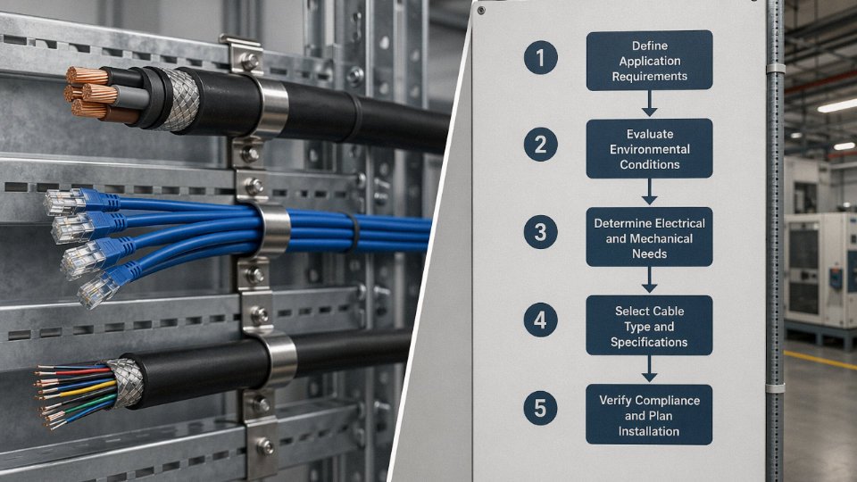
By the time you’ve worked through conductor materials, insulation chemistry, shielding architectures, and certification stacks, the real engineering challenge is synthesizing all of it into a defensible selection decision under project pressure. The five-step framework below is how experienced specifiers actually work — not perfectly linearly, but with each step narrowing the viable options until one or two candidates remain.
Step 1: Define the Electrical Duty
Start with voltage class, continuous current load, and signal type. These aren’t interchangeable inputs — voltage class determines insulation thickness and test requirements; current load drives conductor cross-section; signal type (power, analog control, digital data) determines whether you’re in power cable territory, instrumentation cable territory, or somewhere in between. For power circuits, also nail down whether you’re dealing with 50 Hz industrial supply, variable-frequency drive output (which generates high dv/dt transients that degrade standard XLPE faster than expected), or DC distribution.
Step 2: Characterize the Environment
Temperature range, moisture ingress risk, chemical exposure, UV exposure, and mechanical stress each eliminate categories. A cable that passes every electrical test will still fail in 18 months if the jacket compound wasn’t formulated for continuous hydrocarbon splash. Don’t rely on the installation contractor to flag this — they usually won’t.
Step 3: Select the Installation Method
Direct burial, conduit, open cable tray, aerial self-supporting, and subsea all impose different mechanical and thermal requirements. Direct burial demands armoring and a robust outer sheath; open tray in an area with fire risk mandates LSZH or fire-retardant ratings; aerial runs need UV resistance and, in longer spans, messenger wire or self-supporting construction. The installation method also affects your derating calculations — bundled cables in a closed tray run hotter than the same cables in free air, sometimes enough to force you up one conductor size.
Step 4: Identify Applicable Standards and Local Codes
Project jurisdiction matters enormously here. A cable certified to IEC 60502-2 is not automatically acceptable on a UL-listed installation in North America. For offshore or marine projects, DNV, Lloyd’s, or ABS approvals may be mandatory contractually even when the local electrical code doesn’t explicitly require them. Pull the project specification documents early and flag any conflicts between the end-client’s spec and what’s commercially available — these gaps have a habit of surfacing at factory acceptance testing, not during procurement.
Step 5: Verify Manufacturer Capability and Certification
Third-party test certificates (not self-declarations), factory audit access, and the ability to supply routine test reports on a per-drum basis are baseline requirements for any serious project cable order. More on the specific red flags below.
Worked Example 1 — 33 kV Wind Farm Collector Feeder, Coastal Environment
A 33 kV collector circuit in a coastal wind farm presents a fairly concentrated set of constraints. Salt fog rules out bare armor without corrosion protection. Direct burial between turbine bases and the substation demands mechanical protection and moisture-barrier construction. The voltage class (33 kV falls in the medium-voltage band, typically requiring 12/20 kV or 19/33 kV rated cable depending on system earthing) mandates XLPE insulation at this level — paper-insulated lead-sheathed cable is legacy technology and practically unavailable for new projects at reasonable lead times anyway.
Working through each step: the electrical duty is 33 kV, three-phase, with a feeder current typically in the 200–400 A range depending on wind farm capacity and collector circuit grouping. That narrows conductor cross-section to roughly 95–185 mm² aluminum (aluminum makes sense here — the burial runs are long, weight savings in trenching are real, and aluminum’s corrosion performance under XLPE insulation is acceptable). Environment is coastal with high humidity and salt-laden air, eliminating uncoated steel wire armor in favor of galvanized or, better, aluminum wire armor. Installation is direct burial in trefoil formation.
The result after filtering: a 3-core 95 mm² aluminum conductor, XLPE insulated, aluminum wire armored, HDPE outer sheathed cable to IEC 60502-2. The HDPE sheath outperforms PVC in coastal UV exposure and resists moisture permeation better over a 25-year design life. This is a fairly standard specification for European and Asian offshore-adjacent wind projects, and any manufacturer worth considering should be able to provide type test certificates to IEC 60502-2 without hesitation.
Worked Example 2 — Multi-Core Control Cable, Offshore PLC Cabinet
Offshore platform installations impose simultaneous constraints that often catch procurement teams off guard. Fire performance is non-negotiable — LSZH jacket is typically mandated by platform safety regulations, not just good practice. Oil resistance is needed anywhere near deck level. And electromagnetic interference from variable-speed drives, radar systems, and adjacent power cables makes individual pair or overall shielding effectively mandatory for signal integrity on analog loops.
Starting from Step 1: the electrical duty is low-voltage control signaling, typically 0–10 V or 4–20 mA analog loops, plus discrete I/O. Step 2 flags oil exposure, salt atmosphere, and fire risk. Step 3 is conduit and cable tray within the platform module. Step 4 typically points to IEC 60092 (marine) or specific platform owner specifications, often incorporating IEC 60228 Class 2 conductors and IEC 60332-3 flame test requirements. Step 5 is where you verify the manufacturer actually holds the relevant DNV or equivalent marine type approval — not just that they claim it.
The filtered result: a multi-core (typically 4–24 pairs or triads) overall-shielded and individually shielded control cable, LSZH jacket, oil-resistant compound, with conductors sized at 0.75–1.5 mm² depending on loop length and permissible resistance. Drain wires terminating at the control panel ground bus, not floating. This is not a catalog standard item everywhere — short lead times require a manufacturer with flexible lay-up capability.
Total Cost of Ownership: Where the “Save on Cable” Logic Falls Apart
Cable material cost typically accounts for only 20–40% of total installed cost — the lower end on simple above-ground tray runs, the higher end on direct-burial or submarine installations where excavation and backfill dominate. Terminations, conduit, pulling labor, and commissioning testing make up the balance. Underspecifying to save 8–12% on cable unit price and then experiencing one premature insulation failure that requires trench excavation or platform cable tray pullout will erase those savings immediately, usually with production downtime on top.
Cable material cost is typically only 20–40% of total installed cable cost, with labor, conduit, and terminations making up the remainderTrue
This range is consistent with installed cost analyses across industrial construction projects; the exact split depends heavily on installation method, labor market, and cable routing complexity
The TCO argument also applies to conductor sizing. A conductor one size larger than the minimum thermal requirement reduces resistive losses over a 20–30 year asset life — on a high-load feeder, the energy cost difference can exceed the entire original cable material cost within a few years, depending on load factor and local electricity pricing.
Red-Flag Procurement Checklist
Prices more than 15–20% below the market average for an equivalent specification warrant immediate scrutiny. The margin in legitimate cable manufacturing is not wide enough to absorb that gap honestly — something in the bill of materials has been compromised, whether that’s conductor purity, insulation compound filler loading, or armor wire diameter.
Specific red flags to act on:
- No third-party type test certificates, or certificates that can’t be traced to an accredited laboratory
- Inability or reluctance to provide factory audit access, even with reasonable scheduling
- Conductor resistance values on incoming inspection that exceed IEC 60228 Class 2 limits — this is easy to check with a Kelvin bridge on a drum sample and immediately tells you whether the stated cross-section is real
- Jacket thickness below the minimum stated in the relevant IEC or UL standard — spot-check with a calibrated micrometer on a cross-section cut
- Heat shrink or ferrule terminations supplied with the cable that don’t match the conductor material (aluminum conductors with copper-only lugs, for instance — bimetallic corrosion at the termination is a slow-burn failure that’s very hard to diagnose after installation)
Manufacturer Capability and Supply Chain Verification
Vertical integration from rod drawing through stranding, insulation extrusion, laying-up, and sheathing in a single supply chain matters most on non-standard specifications — unusual cross-sections, special jacket formulations, or combined fire/oil/chemical-resistance requirements. A manufacturer assembling cable from externally sourced semi-finished components has limited ability to control or even verify the compound chemistry at each stage.
Jinda’s production model — covering the full process across five manufacturing bases in China — provides meaningful lead-time consistency for bulk project orders precisely because special-configuration cable doesn’t require coordinating multiple external suppliers. For a procurement manager placing a 500-drum order of a non-catalog specification with a 14-week project window, that supply chain compression is a practical advantage, not a marketing point.
Installation, Jointing, and Maintenance Best Practices That Protect Cable System Lifespan
A correctly specified cable can still fail in three years if installation crews treat it like rope. The design life figure — 30 to 40 years for most industrial power cables — assumes the cable was pulled, jointed, and maintained properly. In practice, that assumption is violated routinely.
Bending Radius: The Rule Most Often Ignored on a Busy Pull Day
Armored medium-voltage cables have a minimum bending radius of roughly 12–15× the overall cable diameter during installation; after laying, the static limit is slightly tighter but the damage usually happens during the pull. Flexible multicore control cables are more forgiving — 6–8× overall diameter is the common working figure — but “flexible” does not mean infinitely bendable.
The insidious part: insulation stress concentrations and screen damage from over-bending are invisible immediately after installation. The cable passes initial commissioning tests without a problem. The failure shows up 18 months later as a phase-to-earth fault under load cycling, and by then nobody remembers that tight bend at the cable tray corner near the motor control center. Always set up proper cable rollers at changes of direction and use a tugger with a controlled feed speed. Pulling by hand around a steel conduit elbow is how you quietly destroy a £200-per-metre 11 kV cable.
Pulling Tension and Sidewall Bearing Pressure
Maximum sidewall bearing pressure in conduit bends is generally held below 300–500 N/cm, depending on cable construction and jacket material — the tighter the bend radius and the heavier the cable, the faster you burn through that budget. For long horizontal runs, calculate pulling tension before the crew starts; the basic formula (tension = coefficient of friction × cable weight per metre × run length) is not complicated, but it is almost never done on smaller jobs. Conductor stretching and jacket tearing are the consequences when it is skipped.
A tension-limiting swivel and a calibrated pulling winch are standard on any serious HV cable installation. If the site is using a borrowed farm winch with no load readout, that is a warning sign worth escalating before the cable leaves the drum.
Jointing and Termination: Stress Cone Geometry Is Not Optional
For medium-voltage power cables, the termination is statistically the most likely failure point. Heat-shrink and cold-shrink kits are both effective when applied correctly; cold-shrink has the practical advantage of no open-flame requirement in hazardous areas. What kills MV terminations is improper stress cone geometry — the stress cone exists to redistribute the electric field concentration at the screen cutback, and if the installer skims through the penciling, taping sequence, or positions the cone even a centimetre out of spec, that point becomes a partial discharge initiation site. It may hold for years before it carbonizes through.
Improper stress cone installation at MV cable terminations is one of the leading causes of premature medium-voltage cable failure in industrial plants.True
Electric field concentration at the screen cutback, if not managed by correct stress cone geometry and installation sequence, initiates partial discharge that degrades insulation progressively until failure — documented extensively in IEC 60502 jointing standards and field failure analyses.
Use manufacturer-approved jointing kits matched to the cable’s exact construction and voltage class. Generic kits sourced off the shelf to save a few dollars on a £50,000 cable circuit is a trade worth examining carefully.
Maintenance Intervals That Actually Catch Problems
Infrared thermography surveys on joints and terminations are practical, non-intrusive, and cheap relative to the failure they prevent. On a loaded MV distribution system, an annual IR sweep — or quarterly in high-duty-cycle environments — will surface hotspots well before they become outages. PD online monitoring is the next level: permanently installed PD sensors on critical MV/HV circuits allow continuous trending, so you catch insulation degradation months before flashover rather than scrambling after it.
Insulation resistance (IR/Megger) testing frequency depends on voltage class and operating environment. For LV control and power cables in a clean indoor environment, every 3–5 years is a reasonable baseline. Cables in wet, chemical, or coastal environments warrant annual testing, at minimum. Outdoor aerial cables need visual inspection twice a year — UV degradation of jacket compounds, mechanical damage from wind-induced abrasion, and bird damage are all real failure modes that an IR camera will miss entirely.
Marking, Documentation, and Storage — the Unglamorous Stuff That Saves Hours Later
Permanent, fire-resistant cable markers at both cable ends and at every wall or floor penetration are not optional on any well-run plant. When a fault occurs at 2 a.m., the maintenance technician should not be tracing cable routes by inspection. As-built routing drawings need to reflect what was actually installed, not the design intent — deviations accumulate over years of modifications and eventually no drawing matches reality.
Test records should be retained for the cable’s life. Partial discharge baselines, initial IR test values, and joint installation reports are the only objective reference when a cable’s condition is disputed years later.
Drum storage gets neglected. Store drums on hard, level surfaces — not soil, where flange sinking causes oval distortion. Outdoor storage requires UV-protective wrapping over drum flanges and the exposed cable face. PVC-insulated cables should not be unreeled below roughly +5°C; cold PVC becomes brittle and surface micro-cracking during a winter pull is invisible but real. In northern climates, moving cable drums into a heated store the day before pulling is a simple habit that prevents unnecessary damage.
Frequently Asked Questions About the Three Main Cable Types
Can a power cable be used as a control cable?
No — and the reasons go beyond simple overcaution. Power cables are engineered around current-carrying capacity and dielectric strength. They are not designed for multi-core signal routing, they carry no shielding architecture, and their thick insulation walls add dead weight and bulk that serves no purpose in a control circuit. More critically, running low-voltage control signals through an unshielded power cable in an industrial environment invites EMI coupling from nearby motor feeders. In practice, you will get erratic PLC inputs, phantom signals, and in variable-frequency drive installations, enough conducted noise to corrupt fieldbus communication entirely. IEC design intent treats these as separate cable families for exactly this reason. Substituting one for the other is a specification shortcut that shows up as a commissioning headache — or worse, an unexplained shutdown six months into production.
What is the difference between armored and unarmored cable, and when is armor required?
Armor — whether steel wire armor (SWA), aluminum wire armor (AWA), or steel tape armor — adds a mechanical barrier against crushing loads, rodent damage, and accidental dig-in during subsequent groundworks. Unarmored cable is fine for protected indoor installations: contained cable trays, conduit runs, or above-ceiling ladderways where nothing is going to land on it. Direct burial changes the equation immediately. IEC 60502 and most project specifications for industrial plants mandate armoring for buried routes, any run through areas with mechanical hazard, and cable tray installations in process areas where maintenance traffic or dropped tools are realistic risks. AWA is the preferred choice where stray current or magnetic loss is a concern — aluminum does not form a magnetic circuit the way steel does, so it avoids the eddy current heating that can occur with SWA on large single-core cables.
How do I know if a cable is genuinely LSZH compliant?
A manufacturer’s declaration on a data sheet means almost nothing without supporting test documentation. What you need are two specific third-party laboratory reports: IEC 61034-2 for smoke density (minimum 60% light transmittance under the test conditions) and IEC 60754-2 for halogen content, where HCl emission must fall at or below 0.5%. Ask for both, check that the issuing laboratory is ILAC-accredited, and confirm the test was performed on the actual compound used in your order — not a legacy sample from a different production run. This matters most in tunnels, offshore platforms, data centers, and public buildings where smoke toxicity during a fire event directly affects evacuation outcomes.
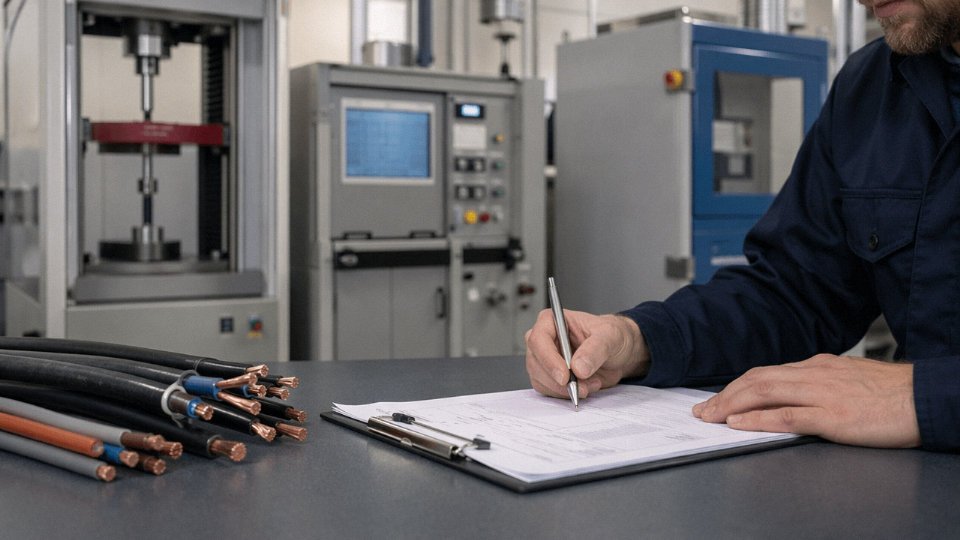
IEC 61034-2 requires minimum 60% light transmittance to classify a cable as low-smoke.True
IEC 61034-2 specifies that the minimum light transmittance during the smoke density test must be at least 60% for the cable to meet the low-smoke requirement.
What conductor cross-section should I use for a 100 A, 415 V three-phase motor feeder?
A 35 mm² copper XLPE cable is a reasonable starting point under IEC 60364, but “starting point” is the right framing. The actual selection requires applying derating factors for installation method (in conduit versus open tray), grouping with adjacent cables, and ambient temperature — at 40°C in a conduit bundle with three other loaded circuits, your usable ampacity drops noticeably. You also need to verify volt-drop over the route length, particularly on feeders longer than roughly 50–80 m. Get lazy with those correction factors and you will either undersize the cable and see nuisance thermal trips, or oversize it unnecessarily and pay for copper you did not need.
Is aluminum conductor cable suitable for building wiring?
Modern aluminum conductor cable — Class 2 stranded construction, minimum 16 mm² — is entirely acceptable for fixed building wiring under current IEC standards, provided you use proper aluminum-rated terminations throughout. The old concern about aluminum oxide causing resistance buildup at joints is real but manageable: bi-metallic compression lugs and anti-oxidant jointing compound deal with it reliably. Where aluminum gets into trouble is when installers use terminals designed for copper without adjustment, or when someone re-terminates a joint years later without understanding what they are working with. The material is not the problem; the lack of aluminum-specific installation discipline is.
How does Jinda support customers who need non-standard cable configurations?
Jinda’s engineering team works directly with procurement and project engineers to develop cable configurations that standard catalog products do not cover — unusual conductor cross-sections, specialized jacket compounds for chemical resistance or extreme temperature exposure, custom multi-core layouts for complex control systems. That process is backed by in-house type testing capability and established export certification workflows for IEC, UL, and BS requirements. For projects where third-party witness inspection is part of the contract, Jinda coordinates that through its production bases rather than treating it as an interruption.
What is the typical lead time for a large-volume specialty cable order?
Standard product lines generally ship within 4–8 weeks for large volumes, depending on raw material availability — copper rod pricing and XLPE compound supply can shift that window, and it is worth asking about current raw material position when you place an inquiry. Custom or special designs typically run 8–16 weeks once the specification is locked, accounting for compound qualification, tooling if new die sets are needed, type testing, and any factory witness inspection scheduling. Jinda’s five production bases give real capacity flexibility for phased deliveries or urgent orders — though “urgent” on a specialty cable is still measured in weeks, not days, and anyone telling you otherwise on a genuinely custom design is worth questioning.




