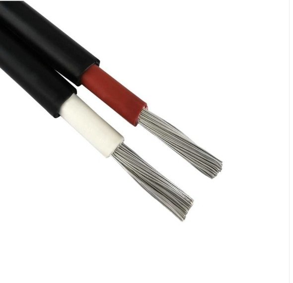
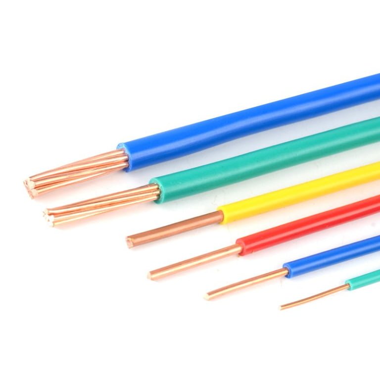
Ordering the wrong product — calling out “cable” on a purchase order when the application actually needs a single insulated wire, or vice versa — sounds like a minor terminology slip until the shipment arrives and nothing fits the conduit, the termination block, or the rated voltage requirement. Rework labor, expedited freight, and line downtime can stack up fast. A single mis-specified run on a mid-size panel build can cost anywhere from a few hundred to several thousand dollars depending on conductor size and how far into the installation the error surfaces. Getting the distinction right at the specification stage is the cheapest fix available.
A wire is a single electrical conductor — solid or stranded — with or without insulation, running from AWG 40 (0.08 mm diameter, used in instrumentation and signal circuits) up to AWG 0000 (11.68 mm diameter, for heavy power service). A cable is an assembly of two or more conductors — or one conductor plus shielding — bound together under a common outer jacket, such as a 4-core 240 mm² low-voltage power cable rated to 1 kV. The two terms are not interchangeable.
What makes this genuinely interesting from an engineering standpoint is that the line between them blurs in practice more often than textbooks admit. A coaxial cable carries one signal path but has multiple concentric layers. Some single-core armored products get called cables on datasheets. And in procurement, regional naming conventions — particularly between North American AWG practice and IEC mm² standards — add another layer of confusion that can derail a cross-border order. Understanding exactly where wire ends and cable begins, and why the construction difference matters for derating, installation method, and code compliance, is worth working through carefully.
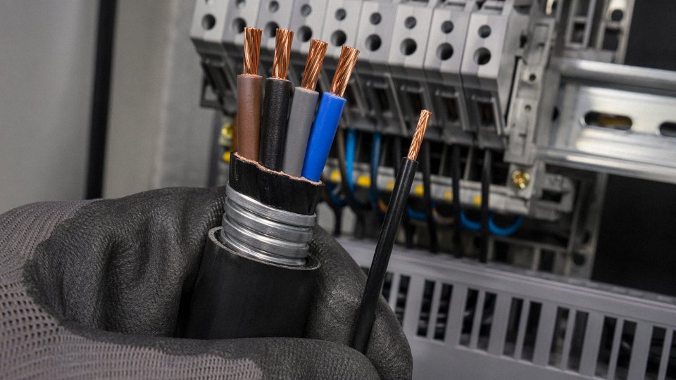
Precise Technical Definitions: What Qualifies as a Wire and What Qualifies as a Cable
Start with the standards, not the catalog. The word “wire” gets used loosely everywhere — retail packaging, purchasing orders, even some engineering drawings — but once you’re writing a spec or signing off on an installation, the definition has legal weight.
What a Wire Actually Is
Per IEC 60050-461, NEC Article 100 (NFPA 70), and BS 7671 definitions, a wire is a single electrical conductor. That conductor is typically copper, aluminum, or a copper-clad aluminum alloy, and it exists in one of two states: bare or individually insulated. Nothing more.
Bare wire shows up in busbar assemblies, earthing grids, and overhead transmission lines — situations where the surrounding air, or a purpose-built enclosure, provides the necessary isolation. Insulated wire adds a single layer of dielectric material (PVC, XLPE, PTFE, silicone, and others depending on temperature and chemical exposure requirements) directly over the conductor. Building wire, hookup wire inside control panels, appliance wiring — these are all wires in the strict sense.
Conductor geometry matters here too. IEC 60228 classifies conductors into classes that apply equally whether you’re talking about a standalone wire or a conductor sitting inside a cable:
- Class 1: Solid conductor — one piece of drawn metal. Stiff. Used in fixed installations where flexibility is irrelevant and you want minimum resistance per cross-section.
- Class 2: Stranded — multiple wires twisted together for a practical combination of rigidity and some flex tolerance. The workhorse for most fixed wiring.
- Class 5: Flexible stranded — fine wires, tightly bunched, designed for repeated bending. Think portable tools, appliance leads, anything that moves.
A single AWG 12 copper conductor with THHN insulation sitting on a reel is a wire. Pull three of those into a conduit separately, and you still have three wires — not a cable.
What Makes an Assembly a Cable
A cable is an assembly of one or more insulated conductors — or, in certain constructions, a mix of insulated and bare conductors — bound together within a common protective outer sheath. That outer sheath is the defining element. It may be a simple extruded PVC jacket, an LSZH (low-smoke zero-halogen) compound, a corrugated aluminum or steel armor, or a combination of bedding, screen, armor, and oversheath layers stacked in sequence.
The sheath does real work: it holds the assembly together for installation, provides mechanical protection, maintains conductor spacing, and forms the boundary that the installation standard is testing for compliance. BS 7671 and IEC 60502 both treat the cable as a single product with defined electrical, mechanical, and fire performance characteristics — characteristics that depend on the whole assembly, not just the conductor inside.
The Edge Cases That Trip People Up
Coaxial cable is the one that confuses people most. It carries a single signal conductor — by the naive definition, “just a wire” — but the concentric shield, dielectric layer, and outer jacket make it unambiguously a cable under every standard. The assembly structure is what classifies it, not the conductor count.
Twin-and-earth building cable (common in UK domestic wiring to BS 7671) contains two insulated line conductors plus a bare CPC (circuit protective conductor), all three enclosed in a flat PVC outer sheath. Three conductors, one of them bare — still a cable because of that enclosing sheath.
In engineering specifications and installation codes, 'wire' and 'cable' are legally distinct terms with different testing, marking, and installation requirements.True
IEC 60502, NEC Article 100, and BS 7671 each define these terms explicitly. Using the wrong product classification in a specification can result in failed inspection, insurance voidance, or code non-compliance depending on jurisdiction.
In everyday trade speech, “wire” gets used for nearly anything with a conductor in it. That’s fine for casual conversation. The moment you’re writing a bill of materials, specifying a product to a supplier, or approving a cable schedule for a panel build, the distinction is binding. A procurement manager who orders “wire” when the spec calls for armored cable is buying the wrong product — full stop.
Anatomy Compared: Internal Construction of a Wire Versus a Multi-Core Cable
Crack open a piece of electrical wire and a multi-core armored cable side by side, and you’re looking at very different animals — even if your supplier’s catalog lumps them both under “cable.” Understanding what’s actually inside each one isn’t academic. It changes how you read datasheets, how you specify to procurement, and how you catch a quality shortcut before it becomes a fault on the floor.
The Wire: Two or Three Layers, Nothing More
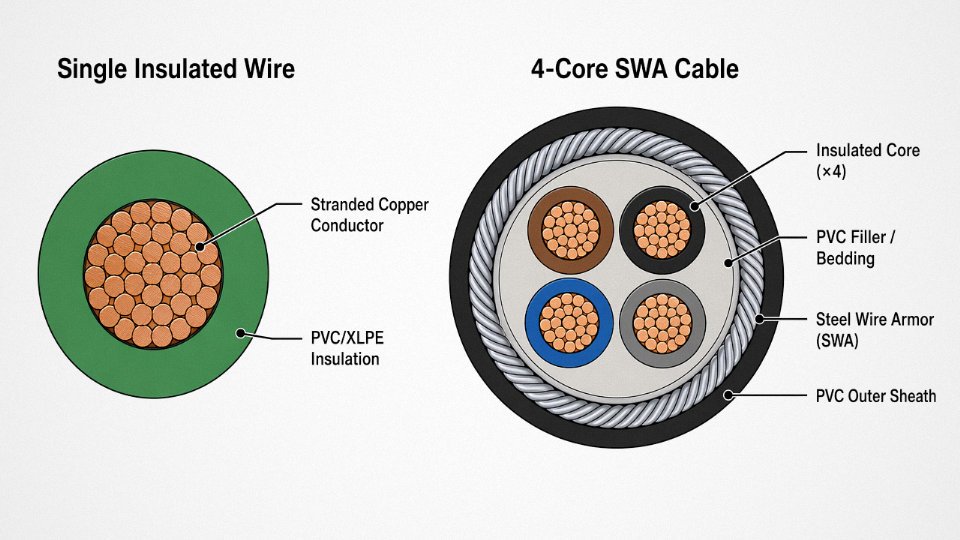
A wire is structurally simple. At its center is the conductor — either a solid rod drawn down to final gauge, or a bundle of smaller strands twisted together. Solid conductors are cheaper to produce and exhibit lower DC resistance per cross-section, which is why you’ll find them in fixed wiring inside panels, conduit runs, and building distribution systems. Stranded conductors tolerate bending without work-hardening and cracking, making them the default choice anywhere the wire sees movement during installation or operation.
Wrapped directly over the conductor is the primary insulation — PVC for general low-voltage use, XLPE where you need better thermal performance (roughly up to 90°C continuous versus 70°C for standard PVC), rubber compounds in high-flex or outdoor applications, and PTFE where chemical resistance or very high temperature ratings matter. That insulation layer thickness is tightly specified; on a 1.5 mm² conductor, you’re typically looking at 0.7 mm nominal, and shaving even 0.1–0.15 mm off that wall is a classic cost-cutting move you’ll see from lower-tier manufacturers.
Color coding may be applied to the insulation surface or extruded as a stripe. That’s it. No further assembly. A wire is complete at this point.
The Cable: Layer by Layer
Where a wire stops, a cable keeps going.
Each insulated conductor inside a multi-core cable is called a core. Those cores carry individual color codes or sequential number printing per IEC 60446 — brown, black, grey, blue for a 4-core low-voltage cable is the standard European sequence, though you’ll still encounter older black/red/yellow/blue conventions in retrofit projects, which is a genuine source of wiring errors during maintenance if the team isn’t paying attention.
Once the cores are laid up together (typically twisted or bunched), the assembly needs to hold a round profile. Loose voids between cores create mechanical weakness and make the outer layers eccentric. Fillers — PVC compound strips, polypropylene string, or paper wrapping in older designs — pack those voids. This isn’t a minor detail: a cable with inadequate filler will flatten under sidewall pressure in a conduit bend, and you’ll see insulation damage at that point eventually.
Next comes optional inner bedding, which cushions the cores against the armor layer above it. Then armor: SWA (steel wire armor) for direct burial and mechanical protection in most industrial and infrastructure work, AWA (aluminum wire armor) where weight matters or magnetic interference is a concern, aluminum foil or braided copper for screened signal and control cables. The armor selection isn’t interchangeable — SWA significantly increases a cable’s weight and pulling tension limits, which matters when you’re threading 630 mm² four-core through a cable tray over 80 meters.
The outer sheath — PVC, LSZH, PE, or rubber — is the final layer, chosen for the installation environment: LSZH in tunnels and confined spaces where toxic smoke is the risk, PE for direct burial where moisture ingress is the enemy.
Conductor Geometry and the AWG vs. mm² Problem
IEC standards classify conductors by flexibility class. Class 1 and 2 are solid or minimally stranded, suited to fixed installations. Class 5 moves to fine stranding for flexible cables. Class 6 goes finer still — this is what you want in trailing cables, robotic arm wiring, or any application involving continuous cyclic flexing, where a Class 2 conductor would fatigue and fracture within months.
Cross-section in the IEC world is expressed in mm² — the actual conductive area of the conductor, calculated from individual wire diameter and strand count. AWG runs the opposite direction numerically (higher AWG = smaller conductor), and the gauge number describes a diameter relationship, not a direct area. A 10 AWG conductor is roughly 5.26 mm², but “roughly” is doing real work in that sentence: whether it’s solid or stranded changes the actual fill diameter, and that affects conduit fill calculations. Mixing the two systems in a procurement spec without explicit conversion is a reliable way to end up with undersized conductors.
IEC 60228 Class 5 stranded conductors are required for flexible cables subject to continuous movement, whereas Class 1 solid conductors are not suitable for such applications.True
IEC 60228 directly specifies conductor class requirements by application type; Class 5 fine-wire stranding is defined for flexible cables, and Class 1 solid conductors are explicitly intended for fixed installations only.
Layer Comparison at a Glance
| Component Layer | Bare Wire | Single-Core Insulated Wire | 2-Core Cable | Armored Multi-Core Cable |
|---|---|---|---|---|
| Conductor | Present (solid or stranded) | Present (solid or stranded) | Present per core | Present per core |
| Primary insulation | Absent | Present — PVC/XLPE/rubber, ~0.6–1.4 mm typical | Present per core | Present per core |
| Core identification | N/A | Single color or unmarked | Color per IEC 60446 | Color or number print per IEC 60446 |
| Inner filler / bedding | Absent | Absent | Optional — PP or PVC | Present — PP string or PVC compound |
| Metallic screen / armor | Absent | Absent | Optional — foil or braid | Present — SWA / AWA / foil, 0.8–3.5 mm depending on cable size |
| Outer sheath | Absent | Absent | Present — PVC or LSZH | Present — PVC / LSZH / PE / rubber, 1.4–4 mm typical |
Thickness ranges depend on cable cross-section, voltage rating, and the applicable installation standard — numbers narrow considerably once you pin down those three variables.
Electrical Performance Differences: Current Capacity, Voltage Rating, and Signal Integrity
Structural differences between a wire and a cable aren’t just academic. They produce measurable, sometimes dramatic differences in how each conductor performs — and getting this wrong shows up fast, either as tripped breakers, degraded signals, or insulation failures that take a production line down at the worst possible time.
Current-Carrying Capacity (Ampacity)
A single-core wire running in free air will carry more current than the identical cross-section conductor buried inside a multi-core cable. The reason is straightforward: heat. Each energized core inside a cable jacket generates heat, and those cores are packed together with nowhere for that heat to go except through the other cores and out through shared insulation. The cumulative thermal effect forces you to derate.
IEC 60364-5-52 provides grouping correction factors that quantify exactly how bad this gets. In a dense cable tray with multiple cables laid touching — which is how most industrial trays actually look by year three of a plant’s life — ampacity can drop by 35–45% compared to the tabulated single-circuit reference value. That means a 4 mm² conductor you spec’d for 32 A might now be limited to somewhere around 18–21 A in practice. Miss that calculation and you’re overshooting the thermal rating of the insulation. Usually nothing dramatic happens immediately; the insulation just ages faster, and then you get a fault at a random point years later and nobody remembers why.
IEC 60364-5-52 grouping derating factors can reduce cable ampacity by up to 45% in densely loaded cable traysTrue
IEC 60364-5-52 Table B.52.17 and associated correction factor tables confirm that groups of cables installed touching in trays require derating; the cumulative reduction can reach approximately 45% depending on the number of circuits and installation method.
Voltage Ratings — and Why the Dual-Figure Matters
Single wires are typically rated 300/500 V or 450/750 V. Those two numbers are not redundant — they express conductor-to-earth voltage followed by conductor-to-conductor voltage. For a single wire, the distinction is largely theoretical; you rarely run a lone wire with another live conductor immediately adjacent at a different potential.
Multi-core cables are rated 0.6/1 kV at low voltage, stepping up through 3.6/6 kV, 6/10 kV, 12/20 kV, and into transmission-class ratings of 64/110 kV and above. Now both figures matter simultaneously, because the cable carries multiple conductors at different phase potentials within the same jacket. The insulation thickness and dielectric design must handle both relationships at once. Selecting a single-wire insulation standard for a multi-phase cable run is a code violation in most jurisdictions and a genuine arc flash risk.
Signal Integrity: EMI, Crosstalk, and Why an Unshielded Wire Pair Will Eventually Cause Problems
In process instrumentation — 4–20 mA loops, Profibus DP, thermocouple extension runs — an unshielded wire pair picks up electromagnetic interference from adjacent power cables, variable-frequency drives, and switching gear. In a busy cable tray, this isn’t a theoretical concern. It’s the reason your flow transmitter reads 0.3 mA high whenever the 55 kW VFD on the adjacent conveyor starts.
Shielded instrument cables with individually screened pairs plus an overall drain provide 60–80 dB of EMI attenuation depending on shield coverage, termination quality, and frequency range. That’s the difference between a clean 4–20 mA signal and one with enough noise to cause false alarms or poor PID loop performance. Belden 3105A-type constructions or equivalent individual-pair-screened cables are the standard solution in serious instrumentation work; a bare twisted pair is not a substitute regardless of what the budget says.
Capacitance is the less-discussed problem. Multi-core control cables typically exhibit 80–200 pF/m of conductor-to-conductor capacitance depending on conductor spacing, insulation material, and cable geometry. At low frequencies this is irrelevant. But for Profibus at 12 Mbit/s, or any fieldbus with a defined maximum cable capacitance, exceeding the per-meter spec while also running long cable runs pushes you past the signal rise-time limit. A single wire has much lower parasitic capacitance, but no defined characteristic impedance unless it’s part of a matched, twisted, controlled-geometry pair — which by that point is a cable anyway.
Mechanical Protection and the Limits of Bare Insulation
A single wire’s only mechanical defense is its insulation. That’s adequate in conduit or inside a control cabinet. Outdoors, underground, or anywhere subject to foot traffic, moving machinery, or chemical splash, bare insulation offers essentially no crush or abrasion resistance. An armored cable — steel wire armored (SWA) construction in particular — withstands point loads exceeding roughly 1,000 N without conductor damage, handles direct burial without conduit, and resists rodent attack and incidental mechanical contact. In practice, specifying a single wire for any exposed outdoor run is the kind of decision that generates a maintenance call within the first operating season.
Application Mapping: When to Specify Wire and When to Specify Cable Across Industries
The structural differences covered earlier aren’t academic — they translate directly into which product belongs in a given installation. Getting this wrong isn’t a minor paperwork issue. Pulling multi-core cable through a conduit system designed for single conductors wastes labor, increases fill ratio beyond NEC 310.15 or CEC limits, and often forces a re-pull. Specifying bare wire for a direct-buried run to a pump station is a code violation waiting to become a ground fault.
When Single Wire Is the Right Call
Inside a switchboard or control panel, single insulated wire — typically stranded, rated for the panel’s internal temperature class — is the correct choice. Runs are short, fully enclosed, and protected by the panel enclosure itself. Using a jacketed cable here adds unnecessary bulk and makes termination into DIN-rail terminals genuinely awkward. Ferrule crimping on individual stranded conductors is cleaner, faster, and auditable during inspection.
Busbar systems in medium-voltage switchgear work similarly. The busbars themselves carry current; connection jumpers between compartments are short, controlled-environment runs where bare or minimally insulated conductors make more sense than a full cable assembly.
Electronics manufacturing — PCB hookup wiring, internal chassis wiring in variable frequency drives, instrumentation enclosures — also belongs in the single-wire category. You’ll see AWG 22 to AWG 18 stranded wire (roughly 0.33 mm² to 0.75 mm²) used almost universally here, color-coded by function. The wire gauge depends on the current and the thermal class of adjacent components, not just ampacity tables.
Conduit installations under the NEC wiring method are a major case where single conductors are explicitly the right product. THHN/THWN-2 single-core wire pulled through EMT or rigid conduit is standard in North American commercial construction. Each phase conductor, neutral, and ground goes in separately. The conduit itself provides mechanical protection and, in metallic installations, an equipment grounding path. Using pre-jacketed cable here is usually unnecessary and sometimes prohibited by the same conduit fill rules.
When Multi-Core Cable Is the Right Call
Running power from a distribution board to a motor, HVAC unit, or production machine is the clearest case for multi-core cable. You need phase conductors, a neutral (in some configurations), and a protective earth conductor routed together, mechanically protected, and identifiable as a single circuit. A 4-core armored cable with cross-sections from roughly 2.5 mm² to 95 mm² covers most industrial motor circuits up to a few hundred kilowatts — exact sizing depends on run length, installation method, and ambient temperature derating.
Direct-buried circuits require armored cable. Full stop. Steel wire armoring (SWA) or aluminum wire armoring (AWA) resists compaction damage, rodent attack, and incidental dig-ins. A bare or lightly insulated wire buried in a trench will fail; it’s not a question of if.
Wet locations, hazardous areas classified under IEC 60079 or NEC Article 500, outdoor exposed runs, and portable equipment connections all point to multi-core cable — specifically because the overall jacket and, where required, the armor provide the environmental sealing and mechanical integrity that a single wire cannot.
Industry-Specific Patterns Worth Knowing
Oil and gas offshore platforms run on IEC 60092-compliant armored, mud-resistant, flame-retardant cables. The mud-resistance requirement isn’t theoretical — cable routes on a drilling deck get contaminated constantly, and standard PVC jackets soften and track under those conditions. Specifying the wrong jacket compound here leads to early insulation failure and a replacement job that costs far more than the cable itself.
Solar farms use two distinct wire/cable products in the same installation. String wiring between panels uses EN 50618 / IEC 62930 PV wire — double-insulated, UV-stabilized, rated for direct sun exposure and the thermal cycling that comes with it. DC trench runs from combiner boxes to inverters shift to armored DC cables. Mixing these up — using standard building wire for string wiring, for example — creates a UV degradation failure within a few seasons.
Railways are non-negotiable on EN 45545 fire performance. LSZH (low-smoke, zero-halogen) multi-core cables are specified because in a tunnel or rolling stock fire, chlorine gas from burning PVC kills people before the flames do. This is one area where the cable specification directly maps to a life-safety outcome, not just a code checkbox.
In North American commercial buildings, single-core THHN inside conduit is dominant and works well. European residential construction typically uses flat twin-and-earth or multi-core NYM cable clipped directly to surfaces or run in shallow chases — no conduit required, different installation logic entirely. Both approaches are correct for their respective code environments; neither is universally superior.
Data centers split the decision by function. Horizontal structured cabling uses Category 6A UTP — a multi-conductor jacketed cable — because it needs to handle crosstalk performance across its full 100-meter channel length. Backbone runs between floors or buildings shift to single-mode or multimode fiber optic cable where distance or bandwidth demands it. Inside equipment racks, the only place bare tinned copper wire appears is for grounding and bonding jumpers — short, visible, torqued to a specific value and left accessible for inspection. Every other connection in that rack is a terminated cable assembly.
Using standard building wire (THHN) for solar PV string wiring exposed to direct sunlight will cause premature insulation failure.True
THHN insulation is not rated for prolonged UV exposure or the voltage transient profile of PV systems. EN 50618 / IEC 62930 PV wire uses cross-linked polyethylene (XLPE) or equivalent with UV stabilization specifically for this environment.
The pattern across all these cases is consistent: single wire where runs are short, enclosed, and individually protected; multi-core cable where the circuit needs to travel through an uncontrolled environment, carry multiple conductors as a unit, or meet a specific safety standard that requires an integrated assembly.
Material and Insulation Choices: How Conductor and Jacket Materials Change Wire and Cable Performance
The datasheet hands you a conductor cross-section and a temperature rating. What it doesn’t tell you is how badly a wrong material choice compounds across a 20-year installation life — higher joule losses, accelerated insulation aging, or a termination that fails during a summer peak-load event because someone swapped copper for aluminum without re-sizing or changing the lugs.
Conductor Materials: Copper Versus Aluminum in Practice
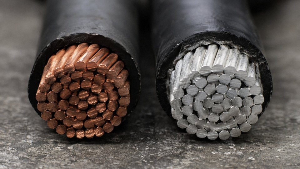
Electrolytic tough-pitch (ETP) copper is the global default for good reason. Conductivity sits at or above 100% IACS, it terminates reliably with standard lugs, and it tolerates the repeated thermal cycling that power circuits go through daily. The drawback is weight and, in recent years, price volatility — copper spot prices have swung enough to shift project budgets meaningfully on large cable packages.
Aluminum conductors weigh roughly 70% less and historically cost 60–70% less per kilogram than copper, which makes them attractive for utility distribution, long overhead runs, and large building risers where weight matters. The catch is physics: aluminum’s lower conductivity means you need to up-size the conductor by approximately 1.6× to match the ampacity of a copper equivalent. A 95 mm² aluminum conductor roughly matches a 70 mm² copper one, but the larger diameter affects conduit fill calculations, termination hardware, and sometimes cable tray loading.
The real operational trap with aluminum is the termination. Aluminum oxidizes quickly once the surface is exposed, and that oxide layer is resistive. Use a copper lug on an aluminum conductor without proper joint compound and anti-oxidant paste, and you’re building a resistance hotspot into the joint. In practice, aluminum cables need aluminum-compatible lugs, correct torque (usually defined tightly in the termination manufacturer’s spec), and periodic inspection in high-cycle applications. Skipping any of those steps is how you end up with a charred panel and a warranty dispute.
Insulation Materials: Temperature and Chemical Environment Drive the Choice
PVC insulation covers the majority of general wiring installations — it’s cost-effective, easy to process, and rated for 70°C conductor temperature under continuous load. That covers most building wiring, control panels, and light industrial applications without issue. The limitation shows up in high-load power cables where conductor temperatures push above 70°C, or in environments with hydrocarbon exposure, where PVC can stiffen, crack, or absorb plasticizers over time.
XLPE (cross-linked polyethylene) handles 90°C continuous and can survive short-circuit conditions up to around 250°C without melting or flowing. For medium-voltage feeders, industrial motor circuits, and renewable energy cabling, XLPE is usually the right call. The cross-linking process changes the polymer structure fundamentally — it’s no longer thermoplastic, which is why it holds its shape under fault conditions where PVC would deform.
PTFE sits at the other end of the temperature scale: rated to 260°C, chemically inert against virtually every solvent and acid, and used in aerospace instrument wiring, thermocouple extension leads, and chemical plant control loops where PVC or XLPE would be degraded within months. It’s expensive, harder to strip cleanly, and rarely necessary outside those specific environments — but when you need it, nothing else will do.
EPR (ethylene propylene rubber) is the choice for applications demanding flexibility in cold conditions. It stays pliable down to around −50°C, making it standard in mining trailing cables that get dragged across frozen ground, offshore platform cables, and shipboard installations that see constant mechanical flexing. EPR also has good resistance to water treeing, which matters in wet environments.
XLPE-insulated cables can withstand short-circuit conductor temperatures up to 250°C, significantly higher than the 160°C limit for standard PVC-insulated cables.True
These limits are defined in IEC 60502 and related standards; the thermosetting nature of cross-linked polyethylene prevents the conductor from cutting through the insulation during a fault event, while PVC softens and flows at much lower temperatures.
Outer Sheath and Armor: What Actually Survives the Installation Environment
Indoor PVC sheaths handle most commercial and light industrial cable pulls. Direct-buried cables in the same PVC sheath family can work, though the grade matters — some PVC compounds used in cheaper cable absorb moisture slowly and lose mechanical properties over years of burial.
LSZH (low smoke zero halogen) sheaths are non-negotiable in tunnels, metro systems, public buildings, and marine vessels. The reasoning is straightforward: in a confined-space fire, halogenated sheath materials release hydrogen chloride gas, which is both toxic and corrosive to electronics. LSZH compounds burn with dramatically reduced smoke density and release no halogen acids. Many European and Middle Eastern building codes mandate LSZH in occupied spaces, and specifying standard PVC cable in those applications is a compliance failure, not a cost saving.
PE (polyethylene) sheath provides superior moisture resistance and is the standard outer layer for submarine cables and underground high-voltage transmission cables. Unlike PVC, PE doesn’t absorb water, which matters across a 30-year burial life.
On armoring: steel wire armor (SWA) gives direct-buried and vertical riser cables the tensile strength to survive installation loads and incidental mechanical damage. For single-core AC cables, though, steel armor creates eddy-current losses because the alternating magnetic field from a single conductor induces circulating currents in the ferromagnetic armor. Aluminum wire armor (AWA) solves this — aluminum is non-magnetic, so the loss mechanism disappears. Corrugated aluminum sheath, used on high-voltage cables, handles both roles simultaneously: it provides mechanical protection and a continuous moisture barrier in a single metallic layer, which simplifies cable construction and reduces overall diameter compared to a separate armor plus radial moisture barrier.
Jinda’s five production facilities manufacture cables across all the insulation and sheath systems described above — PVC, XLPE, LSZH, and rubber — with both copper and aluminum conductors, against IEC, BS, AS/NZS, and GB standard requirements. That range matters for international procurement because a project in the UK, Australia, and Southeast Asia simultaneously may need three different standards from the same supply chain.
| Material | Temp. Rating | Key Strength | Avoid When |
|---|---|---|---|
| PVC insulation | 70°C | Low cost, general use | High load density, hydrocarbon exposure |
| XLPE insulation | 90°C (250°C fault) | High ampacity, fault tolerance | Cost is a hard constraint on small runs |
| PTFE insulation | 260°C | Chemical inertness | Standard commercial installs — cost prohibitive |
| EPR insulation | 90°C, −50°C flex | Cold flexibility, wet environments | Dry, fixed installations where cost matters |
| LSZH sheath | Varies by compound | Fire safety, halogen-free | Rarely avoided where codes require it |
| SWA | — | Tensile strength, burial protection | Single-core AC cables (eddy-current risk) |
| AWA | — | Single-core AC, non-magnetic | Multi-core cables (SWA is fine and cheaper) |
Standards, Certifications, and Compliance Markings: Reading a Wire or Cable Datasheet Correctly
Procurement teams often treat certifications as a checkbox — get the paperwork, move on. That habit costs real money when a shipment fails a site audit, a listed cable fails a fire test during commissioning, or an insurance claim gets denied because the installed product didn’t match its stated standard. Reading a datasheet correctly is a practical skill, not a formality.
Key International Standards and What They Actually Govern
IEC 60227 and IEC 60245 cover PVC- and rubber-insulated cables respectively for fixed installations — the everyday wiring you’ll find in buildings and light industrial panels. IEC 60502 steps up to power cables from 1 kV to 30 kV, with Part 1 covering the 1 kV class and Part 2 handling medium-voltage constructions; if a supplier quotes IEC 60502 without specifying Part 1 or Part 2, that alone is a flag worth questioning. IEC 60228 defines conductor classes — Class 1 (solid), Class 2 (stranded), Class 5 and 6 (flexible) — and it matters because two cables can share the same nominal cross-section yet have completely different conductor constructions, affecting flexibility, termination behavior, and contact resistance.
For North American supply, UL 44 governs thermoset-insulated wires (XLPE, EPR) and UL 83 covers thermoplastic types (PVC, nylon-jacketed). These are not interchangeable with IEC listings; a UL-listed cable will carry UL file numbers and the cUL mark for Canadian acceptance, and those file numbers are searchable on UL’s public registry. UK projects typically require BS 5467 (armored cables with XLPE insulation) or BS 6724 (low-smoke armored variants), and Australian/New Zealand installations fall under AS/NZS 5000. Mixing these up in a specification — which happens more than it should on multinational projects — creates real re-procurement risk mid-project.
How to Read Surface Print Markings
Every compliant cable carries a continuous surface print. A typical IEC-format marking looks like this:
JINDA IEC 60502-1 0.6/1kV XLPE/PVC 4×95mm² 2024
That string tells you the manufacturer, the governing standard and part, the rated voltage (conductor-to-earth / conductor-to-conductor), the insulation and sheath materials, the construction (four cores at 95 mm² each), and the production year. If any element is missing, the cable may not be fully traceable to its stated standard. Cross-section and voltage rating are the two fields most often misrepresented in substitution scenarios — a supplier swapping 70 mm² for 95 mm² in a high-current run, or downrating insulation to cut material cost, will show up in the print if you check it against the purchase order.
Third-Party Certifications Worth Requiring
KEMA, DNV, Lloyd’s Register, and BASEC are the names that carry real weight for international project work — particularly subsea, offshore, and utility-grade installations. UL Listing is non-negotiable for North American code compliance. CE marking is required for EU supply but is self-declared, so it carries less weight on its own than a named third-party test report behind it. CCC (China Compulsory Certification) is mandatory for cables sold into the domestic Chinese market and does not automatically satisfy export-market requirements.
The verification step most buyers skip: look up the certificate number on the certifying body’s live online registry. Expired certificates, certificates covering a different conductor size, or certificates listing a different sheath compound than what was actually shipped — all of these turn up regularly when you check rather than assume.
A CE marking on a cable guarantees it has passed independent third-party testing.False
CE marking on cables is largely self-declared by the manufacturer under EU low-voltage directive requirements. It does not require independent third-party certification unless the product falls under specific notified-body schemes. Always request the supporting test reports and verify against an accredited lab.
Fire Performance Classifications — Where Substitution Risk Is Highest
IEC 60332-1 and -3 cover flame propagation, -3 specifically addressing bunched cable installations where fire spread is a genuine life-safety issue. IEC 60754 tests halogen acid gas emission during combustion, and IEC 61034 measures smoke density. A cable legitimately marketed as LSZH (low-smoke zero-halogen) must pass all three. Standard PVC insulation will fail IEC 60754 and IEC 61034 — it emits hydrogen chloride and dense smoke — which is why substituting PVC for LSZH in a tunnel, data center, or public building is not a minor cost-saving decision; it’s a code violation with potential liability implications in a fire event.
Red Flags in Supplier Documentation
Test reports dated more than three years back deserve scrutiny, especially if the supplier has changed compound suppliers or production lines in the interim. Certificates that list only a cable family rather than the specific construction — conductor class, insulation thickness, sheath material — cannot reliably be applied to the actual product being shipped. And markings that don’t match submitted documentation are the clearest sign of substitution risk: if the print on the drum says one standard and the test report references another, stop and ask before the goods leave the factory.
Cost, Procurement, and Logistics Considerations When Buying Wire vs. Cable in Bulk
Pricing is where the wire-versus-cable distinction stops being academic and starts affecting your project budget in ways that are hard to recover from mid-procurement.
Unit Cost Structure
Wire pricing is essentially a copper or aluminum commodity play. The base is the London Metal Exchange copper settlement (or LME aluminum for aluminum conductors), and the manufacturer adds a fabrication margin that covers drawing, annealing, and basic insulation extrusion. For bare or lightly insulated single conductors, that margin is relatively thin — competitive markets keep it honest.
Cable pricing is a different animal entirely. You’re paying for insulation compound (XLPE, PVC, or EPR depending on voltage class and environment), inner bedding, sheath compound, armor material if specified (steel wire armor adds meaningful weight and cost), and — critically — the multi-core assembly labor itself. Laying up four or five cores, applying tape, extruding a common outer sheath: that’s a series of sequential process steps, each with scrap risk and energy cost. A 4-core 95 mm² steel wire armored cable will commonly run 8–12× the per-meter price of a single-core 95 mm² conductor, and where exactly in that range you land depends on copper price at order date, armor specification, sheath material, and order volume.
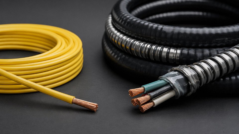
Buyers sometimes try to value-engineer by sourcing single-core wire and installing it in conduit instead of specifying armored multi-core cable. That can work — it’s standard practice in some North American industrial installations — but the installed cost often ends up higher once you account for conduit material, pulling labor, and the coordination overhead of managing four separate reels instead of one drum. Worth running the numbers for your specific site.
Drum and Reel Packaging
Wire typically ships on 100 m or 200 m coils, occasionally on larger 500 m reels for higher-volume AWG sizes. Multi-core power cable ships on wooden or steel drums — for anything above 50 mm² and multi-core, drums of 500 m to 2,000 m are standard. A loaded drum for large-section armored cable commonly weighs 2–5 tonnes, sometimes more for very large cross-sections.
This matters operationally. A 40-foot container holds a finite number of drums constrained by both floor space and axle weight limits; a single 5-tonne drum can eat container payload fast. Port handling requires forklifts or drum-lifting attachments rated for the load — not every port yard has them ready. On site, positioning a 4-tonne drum near a cable route usually means a crane lift or a dedicated cable-drum trailer. Budget and schedule for this. Projects that don’t routinely end up with cable sitting in the wrong location, and re-handling that weight mid-installation is expensive and occasionally dangerous.
Minimum Order Quantities and Lead Times
Standard wire products — common AWG or metric cross-sections with commodity insulation — are often available ex-stock from distributors or on 2–4 week lead times from manufacturers. Custom cable constructions are a different matter: special insulation compounds, non-standard core counts, unusual voltage ratings, or specific certification requirements typically carry 6–14 weeks of manufacturing lead time before shipping even starts. For international orders, add 4–8 weeks ocean freight and customs clearance depending on destination.
Bulk orders exceeding roughly 50 km of a single cable specification usually qualify for dedicated production scheduling, which can actually shorten effective lead time because the manufacturer isn’t slotting your order around competing shorter runs. Worth negotiating explicitly.
Incorrect HS code classification on cable import shipments can result in both customs clearance delays and incorrect duty rates applied to the shipment.True
Wire and cable fall under different HS headings — bare copper wire under 7408, winding wire under 8544.11, power cables under 8544.49, data cables under 8544.42. Misclassification is common because trade documentation often uses 'wire' and 'cable' interchangeably, and customs officers may reclassify shipments, triggering holds and potential duty adjustments.
Import Logistics and HS Code Classification
Get your HS codes right before the first shipment, not after. The classification differs meaningfully: bare copper wire falls under 7408, insulated winding wire under 8544.11, power cables under 8544.49, and data cables under 8544.42. Duty rates vary by these codes, and some destination countries apply anti-dumping measures that are code-specific. A misclassified shipment can sit in customs for weeks while you’re paying demurrage on a container and watching your installation schedule slip.
Supplier Capability Checklist for International Procurement
Before committing volume to any international cable supplier, verify five things directly — not from their marketing materials, but from documentation and ideally a factory audit:
| Factor | What to Verify | Why It Matters |
|---|---|---|
| Production capacity | Monthly output in tonnes or km by product type | Avoids over-promising on tight schedules |
| Certifications | Third-party certs matching destination country (UL, CE, IEC, BS, etc.) | Determines whether product clears customs and inspection |
| ISO 9001 | Certificate date, scope, issuing body | Expired or narrow-scope certs are common — check the actual document |
| Test reports | Factory test reports plus willingness to provide samples for third-party testing | Protects against spec substitution on large orders |
| Project references | Comparable scale international projects with verifiable contacts | The single most reliable indicator of execution capability |
In practice, the certification question trips up procurement most often. A supplier may hold IEC-aligned test reports but not a UL listing — and if your project is in North America or a country that requires UL, that’s a problem you’ll discover at inspection, not before.
Frequently Asked Questions About Wire and Cable Differences
Is a coaxial cable a wire or a cable?
It is a cable — full stop. The confusion is understandable because coax carries only one signal path, which makes people think “single conductor, must be a wire.” But coaxial construction is a precisely layered assembly: center conductor, dielectric insulator (usually solid or foamed polyethylene), braided or foil outer shield, and an outer protective jacket. Four distinct functional layers. That structure satisfies the definition of a cable regardless of signal count. In practice, this matters when you’re pulling coax through a fire-rated penetration or selecting conduit fill — the jacket and shield add meaningful diameter beyond the conductor itself, and those layers contribute to the cable’s impedance characteristics (typically 50 Ω or 75 Ω depending on the construction). Never spec it as a wire on a BOM. You’ll get pushback from any competent electrical inspector.
Can I substitute a cable for a wire in conduit wiring?
Yes, single-core cables can be pulled through conduit, but there’s a catch that trips up a lot of procurement teams working under schedule pressure. The outer sheath of a cable — even a thin one — increases the overall diameter, sometimes by 1–2 mm compared to an equivalent insulated wire. That extra diameter eats into conduit fill ratios fast when you’re running multiple conductors. NEC Chapter 9 tables and IEC 60364-5-52 both govern fill calculations, and exceeding fill limits isn’t a technicality — it causes heat buildup, accelerated insulation degradation, and eventually nuisance tripping or worse. Run the fill numbers before you sign off on the substitution. If you’re already near 40% fill with the original spec, adding a sheathed cable core instead of bare building wire could push you over.
Why does one manufacturer call something a “wire” while another calls it a “cable”?
Honestly, commercial naming is a mess and has been for decades. THHN, which is a single-conductor insulated building wire, gets called “building wire” in the trade — technically correct. But you’ll also find single-conductor products marketed as “single-core cable” by manufacturers targeting export markets that use IEC terminology. Romex, on the other hand, is a genuine cable: multiple insulated conductors plus a ground, all wrapped in a non-metallic sheath. The name tells you almost nothing reliable. Evaluate the datasheet construction drawing, not the product name on the reel label.
What is the difference between a flexible wire and a flexible cable?
A flexible wire — Class 5 stranding per IEC 60228 — is a single conductor built with a high strand count specifically to survive repeated bending without fatigue fracture. Useful inside control panels, for short interconnects, anywhere you need movement on one conductor. A flexible cable takes that concept further: multiple flexible cores, individually insulated, assembled together and covered with a jacket. H05VV-F, SO cord, SOOW — these are flexible cables designed for portable tools, stage lighting rigs, machine tool pendants, anything that sees continuous mechanical movement. The jacket is doing real work here, holding the assembly together under flex and providing abrasion resistance. Substituting a flexible wire where a flexible cable is called for means your conductors are unprotected from each other and from the environment. That’s not a minor oversight.
Does AWG apply to cables, or only to wires?
AWG describes conductor cross-section, and it applies to the individual conductor regardless of context. A conductor is a conductor whether it’s running solo through conduit or sitting inside a 5-core armored cable. Where people go wrong is specifying only the gauge without the core count — “I need 12 AWG cable” is an incomplete specification. You need gauge and number of cores both stated. For international procurement, mixing AWG and mm² notation in the same spec document also creates real risk of misinterpretation; pick one system per project and be consistent.
AWG conductor sizing applies equally to standalone wires and to conductors used as cores inside multi-core cables.True
AWG is a conductor dimension standard (per ASTM B258 and related standards) that defines conductor cross-sectional area regardless of whether the conductor is used alone or assembled into a cable. This is consistent with NEC and IEC 60228 practice.
How does Jinda support customers who aren’t sure which product they need?
With over 35 years of manufacturing experience and a technical team fluent across IEC, BS, UL, and AS/NZS standards, Jinda’s approach is straightforward: send us your installation environment, load requirements, and any applicable certification obligations, and we’ll review the specification at no charge. That includes identifying whether a wire or a cable construction is appropriate, recommending the right conductor class and insulation material, and — before any bulk commitment — producing samples with full third-party test documentation. For procurement managers dealing with unfamiliar regional standards or cross-border compliance requirements, that kind of pre-order validation usually pays for itself many times over in avoided rework.
Selecting the Right Supplier: How Manufacturing Depth Affects Wire and Cable Quality Over Project Lifetime
Once you have the specification right — conductor cross-section, insulation class, armoring type, certification marks — the next variable that will either protect or undermine your project is who actually made the cable. This is where a lot of international procurement goes quietly wrong.
The Trading-Company Problem
A sizable portion of what gets sold as “cable from China” is not manufactured by the company whose name appears on the invoice. Trading companies aggregate stock from several sub-factories, repack it under a single brand, and move on. In a one-off purchase, you might never notice. In a repeat order eighteen months later for the same project’s expansion phase, the copper purity, insulation compound formulation, or even the stranding pitch may have shifted because the trader switched sub-suppliers on price.
That variation shows up in real ways: conductor resistance creeping outside tolerance, insulation thickness slightly thin on one production lot, jacket hardness inconsistent across a 10 km drum order. None of these deviations necessarily trips a go/no-go test on arrival, but over a 20-year service life in a buried utility installation or an offshore platform cable tray, they accumulate into premature failures.
Lot-to-lot variation in conductor DC resistance can cause measurable current imbalance in multi-core cables when conductors from different production batches are terminated in the same panel.True
Even small differences in copper purity (e.g., 99.5% vs. 99.9% conductivity copper) alter resistivity; when cores from different production lots share a busbar, the slight resistance mismatch distributes current unevenly, which accelerates thermal aging on the higher-resistance conductor.
Why Vertical Integration Is Not Just a Marketing Term
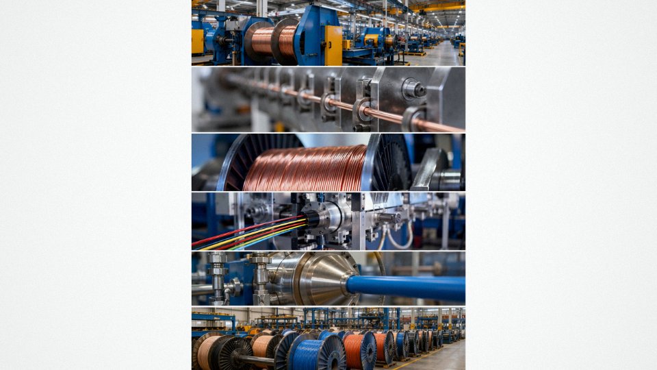
A manufacturer that controls the full process — copper rod drawing, wire drawing, stranding, insulation extrusion, cabling, armoring, sheathing, and final testing — can actually trace back what happened when something goes wrong. They own the test records at every stage. If a customer reports that insulation failed in an unusually cold installation environment, a vertically integrated producer can pull the compound batch records from the extrusion line and the cold-bend test results from that production week.
Jinda’s five production bases covering 470,000 m² of manufacturing space support exactly this kind of traceability. The product range spans 1.5 mm² hookup wire through 35 kV high-voltage power cables, all manufactured under a single integrated quality system rather than assembled from bought-in semi-finished goods. That matters most on projects where you are buying across a wide spec range — say, both control cables and medium-voltage feeder cables for the same substation — because the quality discipline is consistent across all of it.
R&D Capability as a Forward-Looking Procurement Signal
Suppliers without active R&D programs are essentially locked to yesterday’s compound formulations and conductor alloys. That creates real risk on multi-year projects. Fire performance requirements for cables in public buildings have been tightening in most major markets — IEC 60332, EN 50575, and similar standards have all seen revisions in the past decade. EV charging cable requirements are still evolving rapidly. A supplier that cannot reformulate compounds or requalify products in-house will leave you holding an obsolete specification mid-project.
Dedicated R&D investment signals that a manufacturer is tracking these changes and can qualify updated products before the deadline lands on your desk rather than after.
Evaluating for Long-Term Supply Agreements
Infrastructure projects, utility framework agreements, and OEM supply contracts often require 5–10 year commitments. At that horizon, financial stability, production capacity headroom, and post-sale technical support matter as much as initial unit price. Jinda has been supplying international customers across more than 50 countries since 1987 — that reference base is not a marketing stat, it is the due-diligence evidence a procurement manager needs when justifying a long-term vendor selection internally.
Understanding the difference between a wire and a cable is the technical foundation. Getting the specification right keeps you out of code violations and field failures. But choosing a manufacturer with genuine vertical integration, traceable quality systems, and active R&D is what protects that specification across the full project lifetime. Contact Jinda’s technical team for product selection guidance, sample requests, or bulk supply quotations — early-stage technical engagement almost always saves money by the time you reach the order stage.