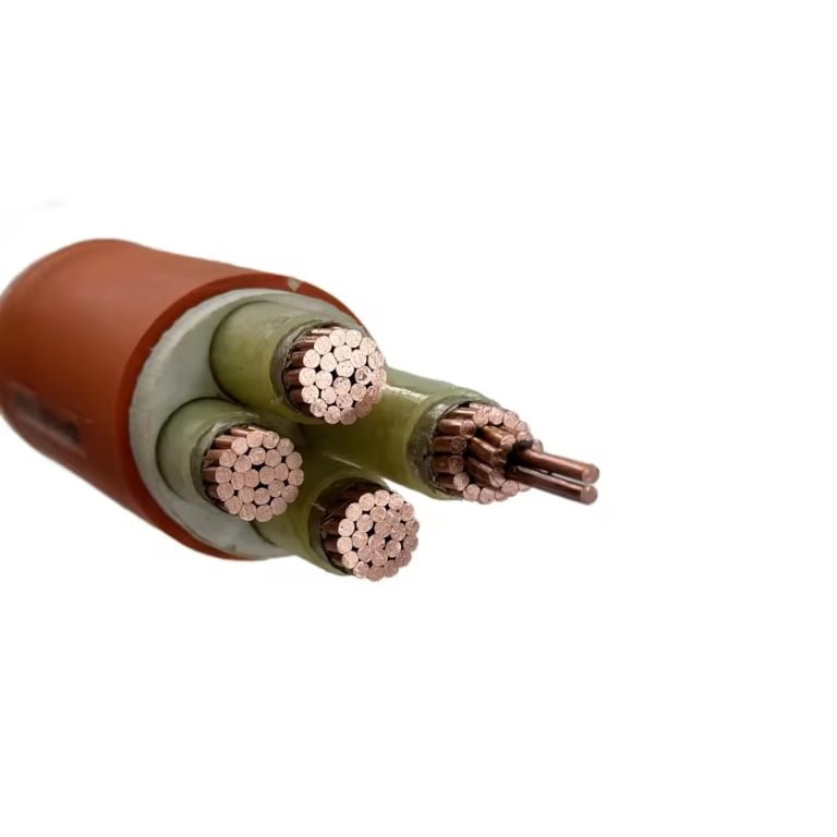
Mislabeling a control cable as a communication cable — or vice versa — is the kind of procurement mistake that looks harmless on a spreadsheet until startup day. Run a 450/750 V switching signal through a cable designed for millivolt-level data transmission and you risk insulation breakdown, corrupted sensor feedback, and nuisance trips that take days to diagnose. On larger projects, that diagnostic time isn’t a minor inconvenience; it’s shift engineers standing around, contractors on day rates, and production targets slipping while someone traces a fault that never needed to happen.
Control cables carry switched voltages — typically 300/500 V up to 450/750 V — to actuators, relays, and motor starters, and are built around current-carrying capacity and power-frequency interference rejection. Communication cables transmit low-voltage signals, generally below 60 V DC, at data rates from a few kbps on RS-485 up to 10 Gbps on Cat 6A or fiber, and their construction prioritizes impedance control, crosstalk rejection, and shielding effectiveness across a broad frequency range. The two cable families are governed by entirely different IEC standards, optimized for fundamentally different physics, and are not interchangeable even when the conductors look similar.
What makes this genuinely tricky in practice is that the physical resemblance between a screened control cable and a shielded fieldbus cable can be convincing — same grey jacket, similar diameter, comparable conductor count. The differences are buried in the dielectric, the shield construction, and the conductor geometry, all of which only matter when the system is under load or noise. That’s what this article unpacks.
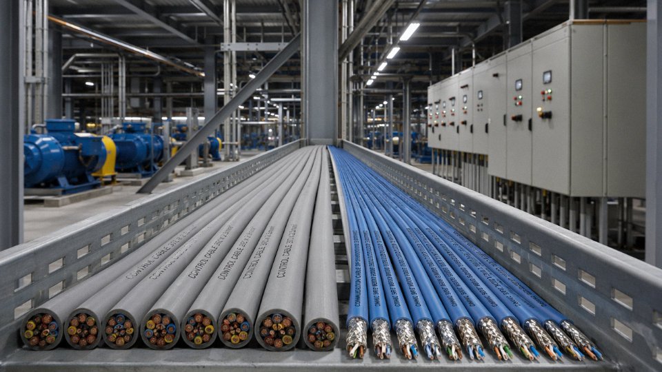
Core Function and Signal Type: What Each Cable Is Actually Carrying
The simplest way to sort this out: ask what the cable is doing with electricity, not just what it’s made of.
What a Control Cable Is Actually Carrying
A control cable transmits commands — close this valve, start that motor, hold this setpoint. The signal isn’t just information; it carries enough energy to act. A 24 V DC solenoid coil draws somewhere between 0.5 A and 3 A depending on the valve body and manufacturer. A motor starter pilot circuit on 230 V AC might pull 2–8 A at the moment of energization. The cable has to deliver that current reliably, hold up against inductive kickback from the load, and survive repeated switching cycles across years of operation.
Typical control signals include discrete on/off switching (pilot voltage circuits to PLC output cards), analog setpoints over 4–20 mA current loops or 0–10 V voltage references, and position feedback from positioners and limit switches. These are slow-changing or quasi-DC signals by nature — a 4–20 mA loop to a control valve positioner doesn’t change much faster than the process it’s regulating, which is usually measured in seconds, not microseconds. Frequency content is dominated by 50/60 Hz power-frequency noise from adjacent power wiring, and the cable design reflects that priority.
What a Communication Cable Is Actually Carrying
A communication cable carries encoded information — Ethernet frames, Profibus DP tokens, Modbus RTU packets, DeviceNet messages, audio waveforms. The electrical energy involved is almost irrelevant. A Profibus DP segment runs at logic voltage levels with signal currents in the low-milliampere range. Ethernet signaling on Cat 5e or Cat 6 operates at roughly ±1 V differential. The cable isn’t energizing anything downstream; it’s preserving the shape of a pulse train so the receiving device can decode it correctly.
This is where the design philosophy diverges completely. Rise time, propagation delay, characteristic impedance, attenuation per unit length, crosstalk between pairs — these are the governing parameters. A communication cable that introduces 3 ns of skew between pairs in a Gigabit Ethernet run might cause intermittent link errors that are genuinely difficult to trace. No one worries about 3 ns of skew in a 4–20 mA loop to a control valve.
The Energy Level Gap and Why It Matters Practically
The voltage and current difference between these two cable types isn’t just academic — it’s a protection engineering problem. A control cable circuit operating at 230–750 V with 1–10 A available fault current will destroy sensitive communication equipment instantly if wiring is crossed or cables share a conduit without proper segregation. Communication interface cards for RS-485, Profibus, or Ethernet are typically rated for signal voltages well below 60 V DC. Some HART interface modules have transient protection, but even they won’t survive sustained cross-connection with a 400 V control circuit. The damage is usually silent at first — a degraded transceiver that starts dropping packets before it fails completely.
| Parameter | Control Cable | Communication Cable |
|---|---|---|
| Signal type | Discrete switching, 4–20 mA, 0–10 V analog | Digital pulse trains, encoded frames, HART FSK |
| Typical voltage level | 24–750 V AC/DC | Below 60 V DC; often 1–5 V logic levels |
| Typical current level | 0.5–10 A | Microamperes to low milliamperes |
| Frequency range of concern | 50/60 Hz power frequency | Kilohertz to gigahertz range |
| Primary performance criterion | Current-carrying capacity, insulation voltage rating | Signal integrity, impedance matching, attenuation |
The HART Gray Area
HART protocol is the most common case where engineers get confused, and reasonably so. A HART-enabled instrument communicates by superimposing a frequency-shift keyed (FSK) signal at 1,200 Hz and 2,200 Hz on top of the conventional 4–20 mA control loop. The wire is doing both jobs simultaneously — carrying an analog control signal and a digital communication signal.
HART communication over a 4–20 mA loop still requires a control cable with capacitance limits, not a generic communication cable.True
The dominant signal is the 4–20 mA current loop, which sets the conductor size and insulation voltage requirements. However, HART imposes a maximum loop capacitance — typically 0.25 µF — to preserve the FSK signal shape. This means cable capacitance per unit length matters, but the cable is still fundamentally a control cable selected for current-carrying duty, not a communication cable optimized for high-frequency impedance matching.
In practice, a standard shielded twisted-pair control cable with capacitance specified at or below roughly 100–130 pF/m works for most HART runs up to a few hundred meters. Using an unspecified generic cable without checking the capacitance figure is a common commissioning mistake — the loop works fine on analog mode and then HART communication is unreliable or completely absent.
Construction Anatomy: How Control Cables and Communication Cables Are Built Differently
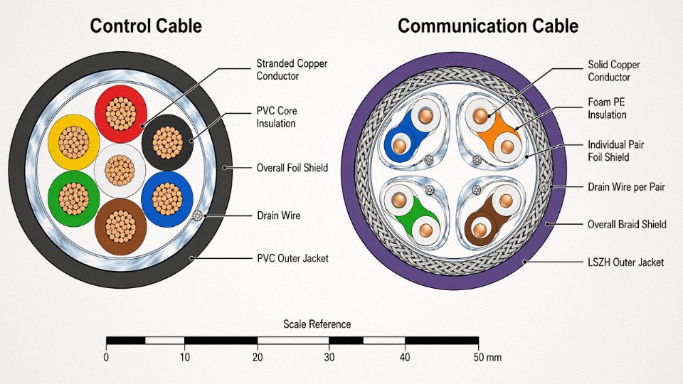
Alt text: Side-by-side cross-section diagram of an industrial control cable and a screened communication cable, with English labels identifying conductor, insulation, drain wire, foil shield, braid shield, and outer jacket layers
Control Cable Construction: Built for Current and Mechanical Abuse
Control cables are workhorses. The conductors run from roughly 0.5 mm² up to 35 mm² — Class 2 stranded, usually plain or tinned copper — because the design priority is carrying enough current to operate a relay coil, actuator, or pilot device without significant voltage drop over a cable run that might stretch 200 meters across a large plant floor. Tinned conductors show up most often in marine or high-humidity environments where bare copper oxidizes fast enough to cause resistance creep over a few years.
Insulation is PVC in the vast majority of installations, rated 300/500 V or 450/750 V per IEC 60227/60245, with XLPE specified when the environment runs hot — think cable bundles inside a motor control cabinet that sees 70–80°C ambient for hours at a stretch. Core colors follow IEC 60446, which matters more than it sounds: a maintenance technician tracing a fault at 2 a.m. who finds non-standard colors loses time fast, and in a live panel that time has consequences.
The outer jacket is typically PVC compounded for oil and chemical resistance, or polyurethane where the cable flexes repeatedly — drag chains, for instance. Shielding is optional and not always present; when it is, a single overall aluminum-foil/polyester tape or a tinned-copper braid handles 50/60 Hz interference rejection adequately for the analog signals most control cables carry. Nobody is engineering 85 dB of broadband attenuation into a cable that runs a solenoid valve.
Communication Cable Construction: Precision All the Way Through
Communication cables are a different discipline entirely. Conductors are typically 22–26 AWG solid copper (Class 1) for structured cabling — Cat 5e through Cat 6A, for example — because solid conductors have lower capacitance per unit length and better high-frequency transmission characteristics than stranded equivalents. Where flexibility is needed, fine-stranded conductors appear, but the electrical trade-off is real and has to be accounted for in link budget calculations.
The insulation material is chosen for its dielectric constant, not primarily for voltage rating. Solid PE, HDPE, or foam PE keeps the dielectric constant tight and predictable across the frequency range the cable must support — foam PE can drop the dielectric constant to roughly 1.4–1.5 versus 2.3 for solid PE, which directly affects propagation velocity and impedance. Every dimension tolerance is tighter than you’d find in control cable: insulation wall thickness variation that would be perfectly acceptable on a 2.5 mm² control core can push a Cat 6 pair outside its 100-ohm ±15% impedance window.
Twist lay length in communication cables is a precisely engineered parameter that directly controls crosstalk between adjacent pairs.True
Each pair in a multi-pair data cable uses a unique, carefully calculated lay length so that magnetic field coupling cancels over short distances. Pairs with similar lay lengths generate mutual inductance that accumulates along the cable length — this is measurable crosstalk that degrades SNR. Control cables may use twisted cores but without the same electrical precision, because crosstalk between a 24 V DC control signal and a neighboring core is rarely operationally significant.
Screened communication cables add individual pair foil shields — each with its own drain wire — plus an overall tinned-copper braid shield. That combination is what gets you 60–100 dB of shielding effectiveness from 1 MHz through 1 GHz, the range that matters for Ethernet, Profinet, and EtherCAT in noisy industrial environments. A control cable’s single overall foil shield simply isn’t constructed to perform at those frequencies; the geometry isn’t optimized for it.
Armoring: Same Option, Different Reason
Both families come in steel wire armored (SWA) and steel tape armored (STA) variants. For control cables, armoring is usually about mechanical protection in cable trays, conduit, or where rodent damage is a credible risk. For communication cables in direct-burial infrastructure runs — connecting outlying field cabinets or perimeter sensors — armoring protects against ground movement, incidental excavation strikes, and compressive soil loads. The armor specification and its earthing treatment differ between the two, and using a communication cable armor grounding practice on a control cable circuit (or vice versa) can introduce ground loops that are genuinely difficult to diagnose after installation.
Electrical Performance Parameters: Voltage Rating, Impedance, Capacitance, and Attenuation
The construction differences described in the previous section aren’t abstract — they translate directly into measurable electrical parameters that appear on datasheets, test certificates, and factory acceptance tests. Get these wrong at the specification stage and you’re looking at anything from nuisance faults to insulation failure under load.
Voltage Rating: Not Interchangeable, Not Even Close
Control cables built to IEC 60227 are typically rated 300/500 V, and the heavier-duty industrial variants used in motor control panels or moving machinery reach 450/750 V. Those aren’t conservative safety margins — they’re the actual insulation coordination values the cable is designed and tested to withstand continuously.
Most communication cables — Cat 5e, Cat 6, Cat 6A, Profibus DP, RS-485 — operate at signal levels well below 60 V DC in normal use. Their insulation systems are sized for that, not for mains-adjacent voltages. Substituting a Cat 6 cable into a 400 V AC control circuit isn’t just a performance mismatch; it’s a direct violation of insulation coordination requirements under IEC 60364. The polyethylene or thin PVC insulation used on data pairs simply isn’t rated for that duty. In practice, the failure mode is often delayed — the cable runs fine for weeks at low load, then fails during a fault event or surge when actual conductor-to-conductor or conductor-to-earth voltages momentarily spike.
Substituting a standard Cat 6 Ethernet cable in a 400 V AC control circuit violates IEC 60364 insulation coordination requirements.True
Cat 6 cables are rated for low-voltage data applications (typically ≤60 V DC signal levels) with insulation systems not designed or tested to IEC 60364 insulation coordination requirements for 400 V AC circuits. Using them in such circuits presents a genuine safety violation and insulation failure risk.
Characteristic Impedance: A Parameter That Doesn’t Exist for Control Cable
Communication cables for structured cabling and fieldbus networks are manufactured to tight impedance targets — 100 Ω (±15 Ω) for Cat 5e/6/6A Ethernet, 120 Ω for Profibus DP, and 150 Ω for some industrial fieldbus variants. These tolerances are maintained through precise control of conductor diameter, insulation wall thickness, and twist pitch, and they’re verified by time-domain reflectometry during production.
Control cables have no characteristic impedance specification. That isn’t an oversight — it’s because they aren’t transmission lines. They carry slowly-varying switched or analog signals where transmission-line effects are irrelevant. Trying to measure characteristic impedance on a multi-core control cable produces a meaningless number.
Capacitance and Bandwidth
Conductor-to-conductor capacitance is where the physics gets concrete. Profibus DP sets a maximum of 60 nF/km. Cat 6 specifies no more than 56 nF per 100 m pair. These limits exist because capacitance and inductance together determine how fast a signal edge propagates and how cleanly it arrives — exceed the limit and you lose usable bandwidth or force the network to drop baud rate.
Control cables routinely show capacitance values three to five times higher than those limits, depending on conductor spacing, insulation material, and whether there’s an overall foil screen close-coupled to the conductors. For their intended application — switching 24 V DC to a solenoid, or carrying a 4–20 mA loop — this doesn’t matter at all. Connecting a Profibus segment with control cable does matter, immediately and measurably, in the form of signal reflections and reduced segment length.
Attenuation, NEXT, and FEXT
Communication cables are tested at multiple frequency points up to 500 MHz for Cat 6A, with pass/fail masks at each frequency. Insertion loss, NEXT, and FEXT are specified because they directly determine whether a 10 Gbps signal survives a 100 m channel. Control cables carry none of these specifications. There’s no attenuation limit to meet because there’s no high-frequency content to attenuate.
| Parameter | Typical Control Cable | Cat 6 Ethernet | Profibus DP | RS-485 Cable |
|---|---|---|---|---|
| Rated voltage | 300/500 V or 450/750 V | ~60 V (signal) | 60 V (signal) | 60 V (signal) |
| Characteristic impedance | Not specified | 100 Ω ±15 Ω | 120 Ω ±20 Ω | 120 Ω ±10 Ω (typical) |
| Max capacitance | 200–400 nF/km (varies) | ≤56 nF/100 m | ≤60 nF/km | ≤52 nF/km (typical) |
| Attenuation at 100 MHz | Not specified | ≤19.8 dB/100 m | Not applicable | Not applicable |
| NEXT at 100 MHz | Not specified | ≥44.3 dB | Not applicable | Not applicable |
| Current-carrying capacity | 1–20 A (depends on CSA and installation) | 0.175 A (PoE limited) | 0.1–0.5 A (signal only) | 0.1–0.3 A (signal only) |
The current-carrying capacity row is worth pausing on. A 2.5 mm² control cable conductor in free air can carry roughly 16–20 A continuously. Cat 6 conductors are 24 AWG — about 0.2 mm² — and while PoE standards push current through them, they are not designed for power circuit duty. The two cable families are optimized for completely different operating regimes, and no amount of creative wiring makes one a safe substitute for the other.
Shielding Strategies: EMI Protection in Control Circuits vs. Data Integrity in Communication Circuits
Both cable types use shields. That’s where the similarity ends — the physics driving each shielding requirement are different enough that treating them as interchangeable causes real failures, often intermittent ones that take weeks to trace.
Why Control Cable Shields Exist
A control cable running a 4–20 mA signal to a PLC analog input is carrying a very low-energy signal alongside, typically, 24 V DC logic or similar levels. The threat isn’t broadband RF. It’s inductive coupling from nearby 400 V or 690 V power cables running parallel in the same tray — the classic 50/60 Hz interference that turns a clean analog signal into a noisy, drifting reading. The shield’s job is simple: wrap the conductors in a grounded conductive layer and short-circuit that induced voltage before it reaches the instrument.
Single-point grounding at the source end (the instrument or transmitter end, usually) is the correct practice. The shield becomes a Faraday cage referenced to one potential. Ground it at both ends and you create a circulating current path — the shield now acts as a shorted secondary winding, and in plants with any ground potential difference between panels (common in large facilities, especially older ones), you’ll inject a continuous 50 Hz current directly onto the drain wire. The symptom is a fixed or oscillating offset on the analog reading. Engineers who’ve chased this problem know how long it can take to find when you’re looking at sensor calibration or card faults first.
Why Communication Cable Shields Work Differently
Shielding an industrial Ethernet cable or Profibus PA segment is a different engineering problem. The interference extends from a few kHz all the way through hundreds of MHz — VFD switching transients, radio transmitters, inductive spikes. At these frequencies, shield effectiveness is measured in dB of attenuation across a frequency sweep, not just at 50/60 Hz. A well-constructed foil-plus-braid shield on a premium fieldbus cable typically achieves 80–100 dB attenuation across 1 MHz to 1 GHz; a basic braid-only shield might deliver 60–75 dB, depending on braid coverage percentage and weave angle.
The grounding philosophy for communication cables also changes with topology and frequency. In many industrial Ethernet installations per IEC 61784, the shield is grounded at both ends — deliberately — because the high-frequency noise immunity requires the shield to be a true RF return path, not a floating Faraday cage. The tradeoff is that you need genuine equipotential bonding between panels; if your ground potential difference is significant (say, more than a volt or two at 50 Hz), you’ll get exactly the low-frequency noise injection problem described above. This is a real design conflict in brownfield plants where equipotential bonding was never part of the original electrical installation.
HART loops are a good contrast case. HART communicates at 1200 baud on a 4–20 mA loop, so the shielding requirement is closer to a control cable than a high-speed data cable — single-point grounding is standard, and the capacitance balance of the cable matters more than broadband shielding coverage. Profibus PA specifies a tightly capacitance-balanced cable (IEC 61158-2 Type A cable: nominal capacitance around 100 pF/m, characteristic impedance 100 ± 20 Ω) with an overall shield; that’s a different spec from a generic screened control cable, and using the wrong cable shortens segment length and introduces reflections.
Three Shield Constructions and Where Each Belongs
Foil shields — typically aluminum-polyester laminate — give 100% optical coverage and perform well at high frequencies. They’re standard in Cat cable designs and most fieldbus cables. The weakness is mechanical: flex them repeatedly and the foil cracks, coverage drops, and high-frequency attenuation degrades unpredictably. Not a problem in a fixed installation; a serious problem in a cable track or drag chain.
Braid shields run 60–95% coverage depending on carrier angle and wire diameter. Lower coverage means slightly lower attenuation at high frequencies, but the braid is mechanically robust, handles flexing well, and performs better at low frequencies (including 50/60 Hz) because the lower resistance of the braid structure improves current-carrying capacity of the shield itself. Most industrial control cables use braid alone for exactly this reason.
Combined foil-plus-braid construction adds both. You get the high-frequency coverage of the foil with the mechanical durability and low-frequency performance of the braid. This is specified in premium Profibus DP cables, high-flex industrial Ethernet designs, and any application near large VFDs where the interference environment is genuinely broadband. It costs more — a foil-plus-braid screened cable typically runs 20–40% higher in material cost than a braid-only equivalent, depending on conductor count and jacket material — but the margin for error in a noisy plant environment justifies it.
Verifying Shield Integrity at the Manufacturing Stage
Shield coverage percentage on braid-screened cables can vary meaningfully between production batches if not actively monitored during winding.True
Braid coverage is a function of carrier angle, wire tension, and machine speed. Without in-line optical verification, coverage can drift below specification without failing visual inspection, leading to reduced shielding effectiveness in the field.
On Jinda’s communication cable lines, automated optical measurement systems check foil overlap and braid coverage percentage continuously during production — not just on a sample basis. Batch-to-batch consistency matters here because a cable that measures 92% braid coverage on a test spool but ships at 78% on a production reel will pass incoming inspection if you’re only checking the test certificate, but it will perform noticeably worse in a high-interference environment. The practical consequence is usually intermittent communication faults that correlate with nearby equipment switching — exactly the kind of fault that’s hard to reproduce and easy to misattribute to software or network configuration.
Applicable Standards, Certifications, and Testing Regimes for Each Cable Family
The two cable families live in entirely separate regulatory universes. That single fact catches procurement teams off guard more often than it should — particularly on projects that mix automation and data infrastructure, where a buyer might assume one compliance framework covers both.
Control Cable Standards: Voltage Integrity and Mechanical Robustness
The primary international framework for PVC-insulated control cables is IEC 60227, which covers fixed-installation cables at 300/500 V and 450/750 V. Rubber-insulated variants fall under IEC 60245. Shipboard control cables answer to IEC 60092, which adds additional requirements for oil resistance, flame propagation, and installation in confined, vibration-prone environments — a meaningfully stricter target than a land-based factory. The European harmonized EN 50525 series aligns broadly with IEC 60227 but includes HAR approval markings relevant for EU customs clearance. In China, GB/T 9330 is the governing national standard; Jinda’s production lines are certified to both GB/T 9330 and the IEC equivalents, which matters for export documentation.
Key production tests under these standards: conductor DC resistance (per IEC 60228 conductor classes), voltage withstand at 2,000 V AC for five minutes without breakdown, insulation resistance measured after immersion, plus bending tests at prescribed mandrel radii. Flame propagation is tested to IEC 60332-1 for single cables and IEC 60332-3 for bunched installation — the bunched test is substantially harder to pass and is the one that actually matters in cable tray runs.
None of these tests evaluate high-frequency attenuation, crosstalk, or impedance. That is not an oversight; those parameters are irrelevant to what a control cable does.
Communication Cable Standards: Signal Fidelity Across Frequency
IEC 61156 covers multicore and symmetrical pair cables used for digital communications. TIA/EIA-568 and ISO/IEC 11801 govern structured cabling for premises installations — these are the standards behind Category 5e, Cat 6, Cat 6A classifications familiar to anyone who has specified an Ethernet backbone. Fiber optic single-mode cabling is defined by ITU-T G.652, and IEEE 802.3 sets the physical layer demands that the cable must satisfy for Ethernet to actually function at rated speeds.
The test suite here looks nothing like control cable testing. Production lines for Category cable run 100% swept-frequency testing on every length — attenuation, NEXT (near-end crosstalk), ELFEXT, return loss, propagation delay, and delay skew are all measured continuously, not on a sampled basis. That 100% electrical sweep is part of why Category cable takes longer to produce per meter and costs more per unit than an equivalent-gauge control cable. A procurement manager pushing a vendor to ship Category 6A on the same lead time as a control cable order is, in practice, asking them to skip tests. Worth knowing.
Fieldbus Cables: The Awkward Middle Ground
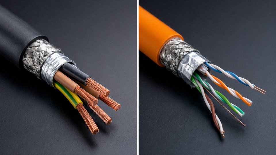
IEC 61158 and IEC 61784 define physical layer requirements for industrial fieldbus protocols — Profibus DP, Foundation Fieldbus H1, DeviceNet, CANopen. These cables are functionally communication cables with tightly specified characteristic impedance (typically 100–135 Ω depending on the protocol), but they look physically similar to a screened control cable pair. Substituting a generic screened control cable pair on a Profibus segment because it “looks right” is a classic commissioning mistake. Reflections at impedance discontinuities cause intermittent node dropouts that are genuinely difficult to diagnose.
A standard screened control cable pair can substitute for a Profibus DP cable if the conductor cross-section matches.False
Profibus DP requires a specific characteristic impedance of 135 Ω ±20% per IEC 61158. Generic control cable pairs are not impedance-controlled and will cause signal reflections, leading to unreliable communication or complete segment failure, particularly at higher baud rates and longer segment lengths.
Fire Performance and LSZH Variants
IEC 60332-1/-3 for flame propagation, IEC 60754 for halogen emission, and IEC 61034 for smoke density apply to both cable families. LSZH (Low Smoke Zero Halogen) construction is mandatory in many tunnel, rail, and public building projects regardless of whether the cable carries control signals or data. The fire-performance designation modifies the jacket and filler compounds but does not change the fundamental electrical architecture — an LSZH Cat 6A cable still needs to pass its full swept-frequency suite; an LSZH control cable still needs the 2,000 V withstand test.
Certification Marks by Region
In Europe, control cables require CE marking under the Low Voltage Directive; both cable families must now also carry CPR (Construction Products Regulation) fire performance class markings — classes Aca through Fca — for permanent building installation. Aca is essentially non-combustible; most industrial cables land in Dca or Eca. In North America, UL 508 covers industrial control wiring while UL 444 applies to communication cables. These are not interchangeable approvals, and a factory destined for the US market that substitutes a CE-marked-only control cable for a UL 508-listed cable will fail inspection. Straightforward, but it catches people.
Typical Application Environments and Installation Scenarios for Each Cable Type
Understanding the electrical differences between control and communication cables only gets you so far. Where things go wrong on real projects is usually at the design stage, when an engineer grabs what’s available on the shelf or specifies a cable family by habit rather than by function. The installation environment and the routing path are where those abstract distinctions become concrete mistakes — or concrete savings.
Control Cable in the Field
Motor control centers are probably the single most common home for multi-core control cable. You’ll find 450/750 V-rated, PVC-insulated control cables running from MCC panels to solenoid valves, motor starters, and pilot devices — carrying 24 V DC logic signals, 110 V AC coil voltages, and occasional 4–20 mA instrumentation loops all in the same cable run, sometimes in the same tray. The conductors are sized for current-carrying capacity and mechanical pull, not for impedance control. Nobody cares about characteristic impedance at 50 Hz.
Relay panel inter-wiring, HVAC damper actuators, crane and hoist pendant circuits — these all share the same requirement profile: moderate current (typically a few hundred milliamps up to a few amps), robust insulation, flexibility where needed, and enough copper cross-section to survive a clumsy cable tie. Instrument loop wiring for 4–20 mA transmitters is a slight edge case; the signal is still a current loop riding on DC, so a shielded control cable (YSLY-JZ or similar) handles it fine, provided the shield is grounded at one end only to avoid ground loops. Fire alarm initiating circuits are another staple — these want mechanical robustness, fire resistance ratings (typically FP200 or an equivalent), and compliance with the relevant installation code, not bandwidth.
The thread connecting all these environments: the cable’s job is to conduct a command or a simple analog value reliably under harsh physical conditions. Flexibility, abrasion resistance, oil resistance in machinery applications, armoring for direct-burial runs — these are the specification drivers.
Communication Cable in the Field
Switch to a Profibus PA segment connecting a dozen field transmitters to a remote I/O panel, and the requirements flip almost entirely. The cable now has to maintain a specific characteristic impedance (100 Ω ±20% for Profibus PA), keep capacitance per unit length within tight bounds, and reject noise across a much wider frequency range than a 50/60 Hz power circuit produces. PROFINET and EtherNet/IP backbone runs in an automotive assembly plant or a food processing facility are routed in dedicated communication trays for exactly this reason — a 10 Gbps Cat 6A run shoved next to a VFD output cable will show degraded BER long before it shows any physical damage.
Building automation networks running BACnet MS/TP over RS-485 are less bandwidth-hungry, but they’re still sensitive to cable capacitance and termination quality. SCADA communication links to remote terminal units — sometimes running kilometers to a pump station or a substation — often use shielded twisted-pair or fiber, depending on distance and the electrical noise environment.
CCTV and access control backbones in a large facility are a good example of how communication cable gets misspecified. Someone on the procurement team substitutes a general-purpose control cable for structured cabling because the voltage levels look similar. The system limps along, then fails intermittently — usually correlated with a nearby drive starting up — and the diagnostic process is expensive.
Outdoor and Underground Runs
Direct-buried communication cables — armored Cat 6, OSP fiber — require moisture-blocking gel fill or water-blocked construction because even slow moisture ingress shifts dielectric constant, raises attenuation, and degrades impedance uniformity over time. This is a genuine failure mode, not a theoretical one; cable pulls that looked fine at commissioning degrade over three to five years in wet soil without proper moisture blocking.
Armored direct-burial control cable also needs moisture-resistant sheathing, but the electrical consequence of some moisture absorption into a PVC outer jacket is far less critical — you’re not trying to hold 100 Ω ±20% across 500 meters of 4–20 mA loop.
Moisture ingress into a direct-buried communication cable degrades impedance uniformity and increases attenuation over time, causing network performance to deteriorate even when the cable shows no physical damage.True
Moisture absorption changes the dielectric constant of cable insulation and filling materials. For controlled-impedance cables (Ethernet, fieldbus), this shifts characteristic impedance and increases insertion loss, which directly degrades signal integrity. This is a documented failure mechanism in OSP cable installations without adequate water-blocking construction.
High-Temperature and Hazardous Area Installations
Furnace areas and kiln surrounds push control cable toward mineral insulated (MI) construction — copper sheath, magnesium oxide fill — which handles continuous temperatures up to roughly 250°C for standard MI and higher for specialist grades. Thermocouple extension cables use PTFE insulation for the same thermal reason, and they’re technically a subset of control/instrumentation cable. These environments essentially never use conventional communication cable.
Explosive atmospheres are where fiber optic communication cable earns its place cleanly. Fiber carries no electrical energy; it’s intrinsically safe in Zone 1 and Zone 2 areas without barriers or Zener isolators. Running Ethernet fiber between a control room and a remote I/O panel in a petrochemical plant is both simpler and safer than running copper Ethernet with intrinsic safety barriers, and the bandwidth is not a constraint.
Marine and Offshore
IEC 60092 covers both types in marine installations, but the sub-standards are distinct. Control cables fall under IEC 60092-376 and similar parts; communication cables reference IEC 60092-370 and related fiber specifications. Both families require halogen-free, low-smoke, fire-resistant construction for enclosed shipboard spaces — that part is shared. The electrical specifications are still entirely separate, and substituting one family for the other to simplify the ship’s cable schedule is a classification society problem waiting to happen.
Routing and Segregation
Most plant engineering standards — and IEC 60364-5-52 at the generic level — require physical separation between power cables, control cables, and communication cables in cable management systems. In practice, 200 mm between power and control trays is a common minimum; communication cables often get their own dedicated tray or conduit. The logic is direct: all the shielding and impedance engineering in a fieldbus cable is partially wasted if it shares a tray with a 400 V motor feeder for 50 meters. Violating segregation rules is the most common cause of the noise problems that shielding was supposed to prevent — and it’s almost always a result of running cables wherever there’s physical space during construction, rather than following the cable routing drawings.
Step-by-Step Cable Selection Decision Framework: Choosing the Right Type for Your Application
Every misspecification I have seen on a plant cable schedule traces back to the same root cause: someone skipped one of the questions below, usually under schedule pressure. Work through these in order. Don’t jump ahead.
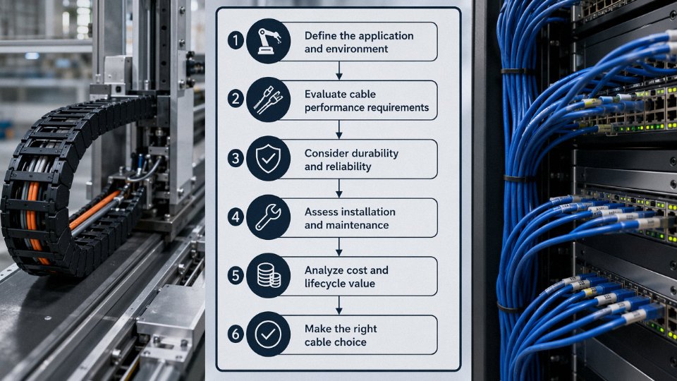
Alt text: A six-step cable selection flowchart with English text, branching from signal type through voltage level, protocol identification, EMI environment, installation conditions, and regulatory standard to reach either control cable specification or communication cable specification.
Step 1 — Define What the Conductor Is Actually Carrying
Ask one question: is this conductor energizing something, or is it encoding information? A wire that closes a contactor coil, drives a solenoid valve, or switches a relay is carrying a command that requires real current and real voltage to actuate a mechanical or electrical device. That is control cable territory. A wire carrying a Modbus RTU frame, a Profibus token, or a 4–20 mA HART signal superimposed on a process variable — that is transferring encoded data between devices, and communication cable construction applies.
In practice the line blurs slightly at analog instrumentation (a 4–20 mA loop is technically signal-level but draws little current and travels long runs). For conventional 4–20 mA without a digital protocol, instrumentation cable is the right family, which shares more construction philosophy with communication cable than with control cable. Worth noting that when HART is layered on top of that same loop, the cable impedance tolerance tightens further.
Step 2 — Determine Operating Voltage and Current
If the circuit operates above 60 V AC, or if the connected load draws more than roughly 1 A, communication cable is categorically excluded. Full stop. Communication cable insulation is designed for signal-level voltages — generally below 60 V DC — and the conductor cross-sections are sized for data, not for driving loads. Select a control cable rated for the system voltage: 300/500 V for most low-voltage automation circuits, 450/750 V where the specification calls for it.
Step 3 — Identify the Protocol or Signal Standard
If a specific fieldbus protocol is in play, the cable physical layer parameters are not optional. Profibus DP Type A mandates a characteristic impedance of 135–165 Ω, a capacitance below 30 pF/m, and loop resistance under 110 Ω/km. Foundation Fieldbus H1 has its own voltage, current, and impedance window. CANbus and RS-485 Modbus have similar hard requirements. Look up IEC 61158 or the relevant Profibus International or FieldComm Group physical layer specification sheet before writing a purchase order — using a generic cable that is “close enough” on paper will cause reflections, CRC errors, and segment instability that take hours to diagnose.
Profibus DP Type A cable requires a characteristic impedance of 135–165 Ω as defined in IEC 61158-2 and Profibus International installation guidelinesTrue
This impedance range is a mandated physical layer requirement for Profibus DP network integrity. Cables outside this range cause signal reflections that degrade network performance, especially at segment lengths approaching 1,200 m at 9.6 kbps or shorter segments at higher baud rates.
Step 4 — Assess the Electromagnetic Environment
A drive room with multiple variable frequency drives running above 50 kW, large motor feeders in adjacent cable trays, and power conversion equipment nearby is genuinely hostile. In that environment, both cable types need appropriate shielding — but the shielding requirements differ. Shielded control cable with an overall braid or foil, grounded at one end (typically the panel end), handles 50/60 Hz interference. Communication cables in the same environment need individually shielded pairs, and the shield grounding scheme depends on the protocol — some protocols require both-end grounding, which creates ground-loop risk if the site’s equipotential bonding is inadequate. Define the grounding scheme before ordering, not after the cable is pulled.
Step 5 — Confirm Installation Environment
Temperature range, chemical exposure, UV exposure, mechanical stress, and fire performance class all determine insulation and jacket material selection — and this applies equally to both cable families. A cable running in an outdoor cable tray in a coastal petrochemical plant needs UV-stabilized, oil-resistant jacket with LSZH fire performance; the same cable run in a climate-controlled clean room needs none of that. Burial depth and whether direct-burial armoring is required adds another layer. Get the installation conditions in writing from the site engineer before finalizing the cable schedule; changing armor or jacket specification after a purchase order is issued is expensive and slow.
Step 6 — Match to Regional Standards and Project Specifications
Confirm which regulatory framework applies: IEC for most international and European projects, UL/NEC for North American installations, or a national standard mandated by the end-client’s country. Control cables fall under IEC 60227, IEC 60245, or IEC 60092 (marine) depending on application. Communication cables reference IEC 61156, TIA/EIA-568, IEC 60189, or ITU-T G.652 for fiber. Cross-check against the project’s cable schedule or Material Take-Off document — a well-written MTO will already specify the standard, voltage rating, conductor cross-section, shielding type, jacket material, and flame/fire class. If the MTO is silent on any of these, raise a technical query before ordering.
Selection Summary Table
| Decision Point | Answer Leads To | Common Error |
|---|---|---|
| Signal type | Energizing a device → control cable; encoded data → communication cable | Using communication cable for valve actuator circuits |
| Voltage / current | Above 60 V AC or above ~1 A → control cable required | Running 110 V AC control on data-grade cable |
| Protocol physical layer | Fieldbus specified → cable parameters are mandated | Substituting generic shielded cable for Profibus Type A |
| EMI environment | High noise → specify shielding type and grounding scheme for each cable family | Ordering unshielded control cable near VFD panels |
| Installation conditions | Temperature, chemical, UV, fire class → insulation and jacket selection | Specifying standard PVC jacket in an outdoor UV-exposed tray |
| Regulatory standard | IEC, UL, or national standard → verify compliance before purchase order | Ordering IEC-rated cable for a UL-listed panel in North America |
Working through all six steps adds perhaps thirty minutes to a specification review. Skipping them can add weeks to a commissioning timeline.
Frequently Asked Questions About Control Cables and Communication Cables
These questions come up repeatedly in procurement reviews, site commissioning discussions, and engineering RFIs. The answers below are direct — no hedging where the technical position is clear.
Can I use a communication cable instead of a control cable to save space in a conduit?
No. Full stop. A Cat 6 UTP cable, for example, carries a voltage rating of around 60–150 V depending on the specific product standard — nowhere near the 300/500 V or 450/750 V insulation coordination required for typical control circuits under IEC 60364. The insulation wall on a 24 AWG communication conductor is optimized for signal integrity, not for dielectric withstand at control-circuit voltages. Running 230 V AC through Cat 6 cores violates insulation coordination requirements directly and creates both shock and fire hazard, particularly in conduits where heat accumulates. Inspectors on any CE-marked or IEC-governed installation will flag this immediately. If conduit space is the real problem, the right answer is a hybrid cable or rerouting — not a voltage-class substitution.
Using Cat 6 cable on a 230 V control circuit violates IEC 60364 insulation coordination requirements.True
IEC 60364-5-52 requires conductors to be rated for the circuit voltage class. Communication cables such as Cat 6 are rated for signal-level voltages only and do not meet the insulation thickness or dielectric withstand requirements for 300/500 V or 450/750 V control circuits.
Can a control cable carry RS-485 or Profibus data signals?
Technically the electrons will move. In practice, the signal degrades fast enough that at any real installation length — say, beyond 10–20 m in a noisy panel environment — you start seeing reflections and noise-induced bit errors. Control cables have no controlled characteristic impedance (Profibus Type A specifies 135–165 Ω), no guaranteed capacitance per meter, and inconsistent pair twist lay. Profibus International is explicit about this: their installation guideline prohibits substituting generic cable and specifies Type A parameters precisely because engineers tried this shortcut in the field and paid for it with intermittent network faults that took days to diagnose. RS-485 is slightly more tolerant, but even there, a high-capacitance control cable limits your segment length and baud rate in ways that generic datasheets won’t warn you about.
What is an instrumentation cable — control or communication?
Instrumentation cables sit in between, which is why the confusion persists. They carry low-level analog signals — 4–20 mA loops, thermocouple pairs, RTD leads — and are insulated to control-circuit voltage classes (typically 300/500 V per IEC 60227). But each pair or triad is individually shielded, which looks more like a communication cable than a standard multi-core control cable. The critical difference from both: instrumentation cables have tighter capacitance limits (often below 100 pF/m per pair) to prevent signal distortion on slow analog signals. They are their own category. Don’t assume a shielded multi-pair control cable meets instrumentation-grade capacitance specs without checking the datasheet.
Why do some communication cables have thick, rugged jackets that look like control cables?
Industrial Ethernet cables for drag chains, robotic arms, or M12 field-assembly applications often use polyurethane or TPE outer jackets 2–3 mm thick, and the overall cable diameter can easily match or exceed a standard 4-core control cable. The jacket is engineered for flexing cycles (sometimes rated to 10 million cycles), oil resistance, and abrasion — the mechanical environment demands it. The inner construction is still impedance-controlled to 100 Ω ±15 Ω with pair twist geometry meeting IEC 61156-5 or equivalent. So the cable looks tough on the outside for good reason, but that doesn’t change what it is electrically. Ordering a standard control cable as a “cheaper substitute” for an industrial Ethernet drag-chain application will destroy your network reliability within weeks.
How do I identify a control cable versus a communication cable when the jacket marking has worn off?
Start with conductor size and count. Communication cables typically use 22–26 AWG conductors arranged in twisted pairs or quads; control cables usually run 0.5–6 mm² conductors, often untwisted. Look for systematic pair twisting with a drain wire — that strongly suggests communication cable. Check the dielectric: foam PE or solid PE insulation on individual conductors points to communication; PVC insulation on each conductor is far more common in control cables. If you have a capacitance meter handy, measure conductor-to-conductor capacitance per meter — values below roughly 50–60 pF/m per pair suggest a communication cable; values well above 100 pF/m are typical of control cable construction. Don’t rely on jacket color alone; color coding is not standardized across manufacturers or markets.
Does Jinda manufacture hybrid cables combining control and communication functions?
Yes. Hybrid cables combining 450/750 V-rated control cores (typically 1.5–2.5 mm² PVC-insulated) with individually shielded data pairs — whether 100 Ω Ethernet pairs or RS-485 pairs — in a single armored outer jacket are a real product category, not a novelty. Applications driving demand include wind turbine tower cables (where routing separate cable harnesses up a tower is expensive and space-constrained), mobile machinery, and process skid wiring where a single cable entry through a gland saves both termination time and ingress-protection headaches. The design challenge is keeping the data pairs electrically isolated from the power cores — physical separation within the jacket and individual pair shielding are non-negotiable. These cables are built and tested to both IEC 60227/60245 requirements for the control cores and IEC 61156 requirements for the data pairs, and the test reports should show both sets of results. Ask for them before accepting delivery.
Why Sourcing Both Cable Types From a Single Qualified Manufacturer Reduces Project Risk
Large EPC projects — a new substation, an LNG terminal expansion, a rail depot fit-out — routinely carry cable material take-off schedules with several hundred line items. A realistic split might be 60–65% control cable by meterage and 25–35% communication cable, with the remainder being power cable. Running two separate vendor qualification processes for those two families costs real time: factory audits, third-party test report reviews, QMS documentation, country-specific certification checks. Consolidating both families under one qualified supplier cuts that workload roughly in half, and on a project with a tight front-end engineering phase, that matters.
Single-Source Qualification Efficiency
Qualifying a manufacturer to IEC, UL, and regional mark requirements (CE, GOST-R, SASO, BV type approval) is not a checkbox exercise. It involves reviewing production process records, raw material traceability chains, and test equipment calibration — once per supplier, not once per product family. When control cables and communication cables come from the same factory under the same ISO 9001-certified quality system, the audit covers both families in a single visit. Procurement managers on multi-discipline projects consistently underestimate how much schedule float gets consumed by managing two separate vendor nonconformance cycles.
Consistent Raw Material Control Across Both Families
Here is where single-source sourcing produces a less obvious but operationally significant benefit. A manufacturer that runs its own copper rod drawing lines controls conductor dimensional tolerance from the rod stage — not just from bought-in coils of varying origin. Conductor diameter variation of even ±0.02 mm can affect insulation wall uniformity on small-gauge communication cables, which in turn shifts the characteristic impedance slightly. For a Cat 5e run that’s fine; for a longer RS-485 segment in a noisy plant, cumulative impedance mismatch can push reflection coefficients toward the edge of spec. When insulation extrusion for both PVC-jacketed control cables and PE/HDPE-insulated communication cables runs on in-house lines with shared process control standards, lot-to-lot variation shrinks. That’s the difference between pulling cable from three different production runs that all test clean individually and having a field termination problem you can’t immediately trace.
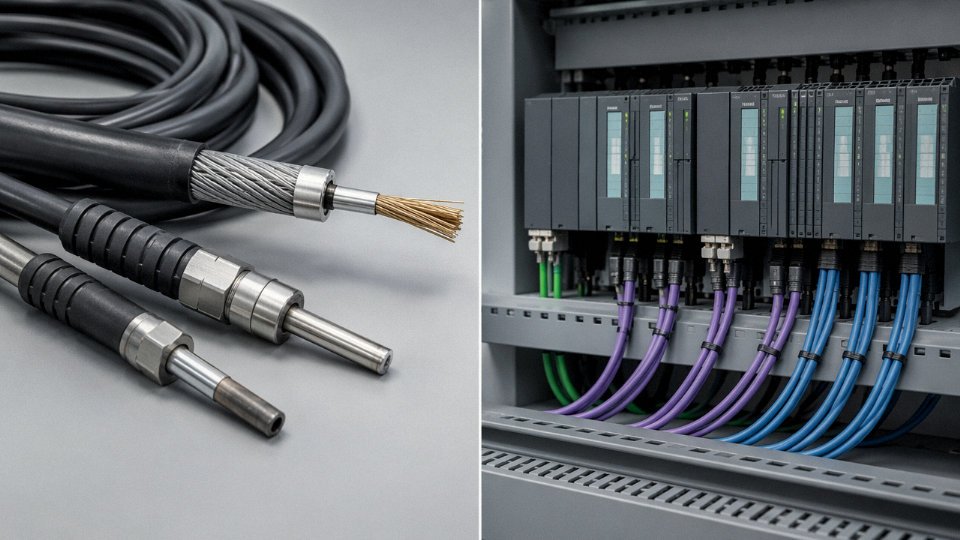
Coordinated Phased Delivery
Site installation sequences don’t wait for lagging cable deliveries. Conduit filling typically has to follow civil work; communication backbone trunking goes in before control homerun pulls. A manufacturer operating across five production bases with a combined 470,000 m² of manufacturing area can stagger production batches to match a project’s phased installation milestones — something a smaller, single-product supplier simply cannot flex to accommodate. Coordination breaks down fast when you’re chasing two vendors across different lead-time windows during the same critical-path window.
Technical Support That Spans Both Families
In practice, commissioning faults rarely announce which cable family they belong to. A ground fault indication on a DCS I/O card might be a damaged control cable screen, or it might be a communication cable laid in the same tray whose drain wire was incorrectly bonded. When the supplier’s application engineers understand both cable types and how they interact in a shared tray environment, root-cause diagnosis moves faster. Managing two separate vendor technical support escalations for the same physical installation zone is, frankly, a waste of everybody’s time.
Jinda exports cables to more than 50 countries and holds multiple country-specific certifications including CE, GOST, SASO, and BV type approval across both control and communication cable families.True
This is stated in the manufacturer's published company profile and product certification documentation, and is consistent with the scale of operations described (five production bases, 470,000 m² manufacturing area, established 1987).
Jinda’s international sales and technical team handles cable schedule reviews, sample requests, and bulk quotation for both product families — structured as a technical partnership from initial BOM review through to long-term supply agreement. If your project is still in the design phase, that’s the right point to get cable specifications aligned. Contact the team directly with your cable schedule and application details.