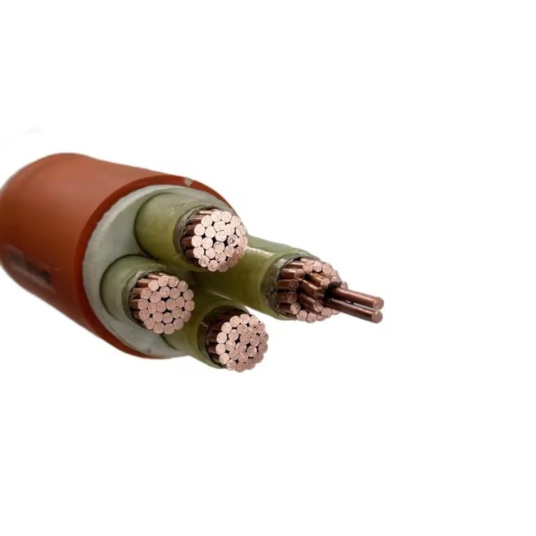
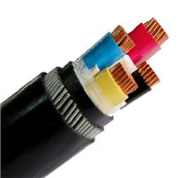
Swapping a control cable for an LT power cable — or specifying the wrong one in a procurement order — is the kind of mistake that looks harmless on paper until the commissioning team shows up and finds insulation that can’t handle the fault current, or a multi-core instrument cable that’s been looped through a panel tray where 400 mm² feeders belong. The resulting rework isn’t just expensive; on a tight project schedule, it can push energization back by weeks and trigger liquidated damages clauses that dwarf the original cable cost difference.
Control cables and LT cables serve fundamentally different electrical functions. Control cables carry low-current signals and switching commands between instruments, relays, and control panels, typically rated 450/750 V or 600/1000 V with conductor sizes from 0.5 mm² to 10 mm² and core counts from 2 to 61. LT (low tension) power cables distribute three-phase or single-phase load current to motors, switchboards, and distribution boards, rated 0.6/1 kV per IEC 60502-1, with conductors running from 1.5 mm² up to 400 mm² or beyond.
What makes this genuinely confusing in practice is that the voltage ratings overlap at the 600/1000 V boundary, the insulation materials often look identical from the outside, and some manufacturers label both types with similar colour sheaths depending on the destination market. The differences that actually matter — current-carrying capacity, conductor sizing logic, shielding requirements, mechanical construction, and how each cable behaves under fault conditions — are buried in the design standards rather than printed on the drum label.
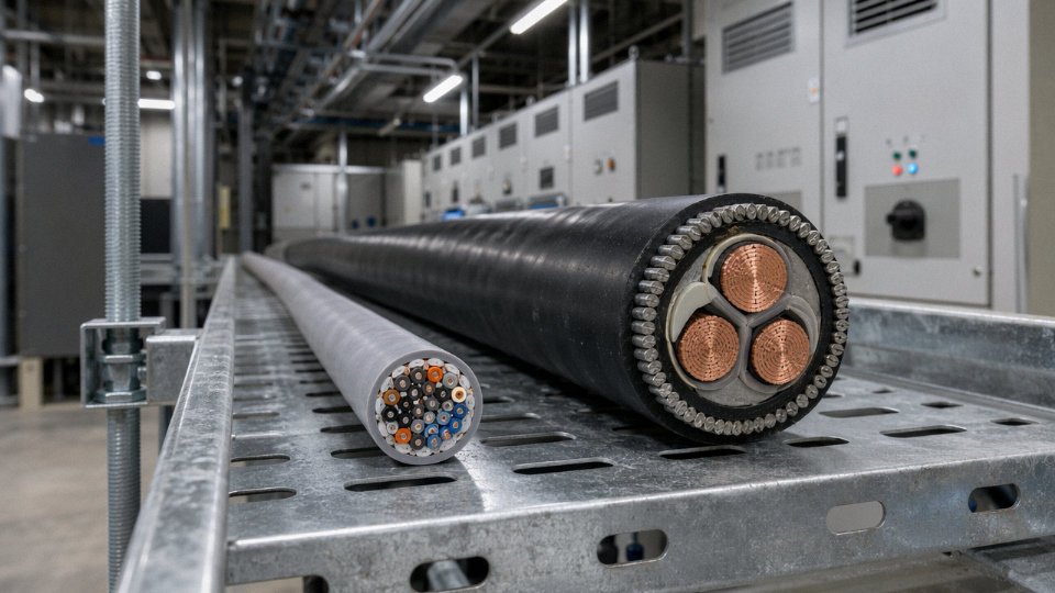
Functional Roles Defined: What Each Cable Is Actually Designed to Do
Before you can make sense of why a control cable has 19 cores and why an LT cable has three, you need to understand what each one is actually doing inside a facility. The construction follows the function. Always.
What Control Cables Are Built For
A control cable’s job is to carry intent — not power. When an operator pushes a start button on a panel, a signal travels through a control cable to a relay or PLC input card. When a temperature transmitter detects an overtemperature condition, its 4–20 mA output rides over a control cable back to a DCS. When two interlocked contactors need to prevent simultaneous energization, the interlock wiring — again, control cable — is what enforces that logic.
The currents involved are modest. Signal circuits typically run from a few milliamps up to maybe 2–3 A in a coil drive circuit; most instrumentation loops sit well below 100 mA during normal operation. This is not the cable doing heavy lifting. The voltage levels are similarly undemanding — most control wiring runs at 24 V DC or 110/220 V AC, well within the 450/750 V or 600/1000 V ratings that standards like IEC 60227 or IEC 60502 assign to this class.
What matters here is signal integrity. A 1-volt noise spike on a 24 V DC control line can cause a spurious trip. A ground loop in an analog signal circuit can corrupt a 4–20 mA reading by enough to throw a PID loop into hunting. This is why multi-core control cables often include an overall screen or individual pair screens — the physical construction is directly answering an electrical problem. The core count reflects the density of signal paths needed: anywhere from a simple 2-core run to a 61-core harness feeding a marshalling cabinet, all routed in a single sheath.
What LT Cables Are Built For
An LT cable’s job is fundamentally different. It moves energy in bulk. From the secondary winding of a distribution transformer to a main switchboard, from a switchboard to a motor control center, from an MCC feeder to a 75 kW pump motor — that’s LT cable territory, rated at 0.6/1 kV per IEC 60502-1.
The design challenge here is thermal, not signal-quality. A cable feeding a 200 A motor load is dissipating real heat across its length under continuous duty. The insulation — typically XLPE or PVC depending on the application — has to endure sustained operating temperatures of 70°C to 90°C for years without degrading. Conductor sizing runs from 1.5 mm² for lighting branch circuits up to 400 mm² or larger for main feeders, because current-carrying capacity is the primary sizing variable. Core counts stay low: single-core for large feeders, three-core or four-core for three-phase circuits, occasionally five-core where a separate earth conductor is required alongside neutral.
Why These Different Roles Produce Different Designs
The divergence in design priorities is not arbitrary. Control cables are optimized around electrical noise immunity, physical flexibility for dense multi-core routing, and stable low-current performance. LT cables are optimized around conductor cross-section, insulation thickness that meets voltage withstand requirements, and thermal performance under load — properties that a control cable simply doesn’t need in the same measure.
The Edge Cases That Cause Real Confusion
In practice, the boundary blurs occasionally. Screened instrumentation cables — used for thermocouples, RTDs, or high-frequency fieldbus signals — are technically a subspecies of control cable, but their shielding construction and impedance characteristics make them a separate procurement category in most plants. On the other side, a 1.5 mm² two-core cable feeding a small panel lamp could physically resemble a control cable while functionally serving as a power circuit. Standards generally resolve this by tying classification to rated voltage and intended use: if the circuit is carrying load current to an end device, it’s a power cable regardless of its size.
A screened control cable can be substituted for a dedicated instrumentation cable in a 4–20 mA loop without signal degradationFalse
Screened control cables and instrumentation cables differ in shielding coverage, drain wire construction, and capacitance per unit length. Using a standard screened control cable in a sensitive analog loop can introduce enough capacitive loading or shield discontinuity to cause measurable signal error, particularly over longer runs or in high-EMI environments.
Getting this baseline right — control cable moves signals, LT cable moves power — is what keeps every downstream decision about sizing, screening, termination, and routing from going sideways.
Construction Anatomy Side by Side: Conductors, Insulation, Screening, and Sheathing
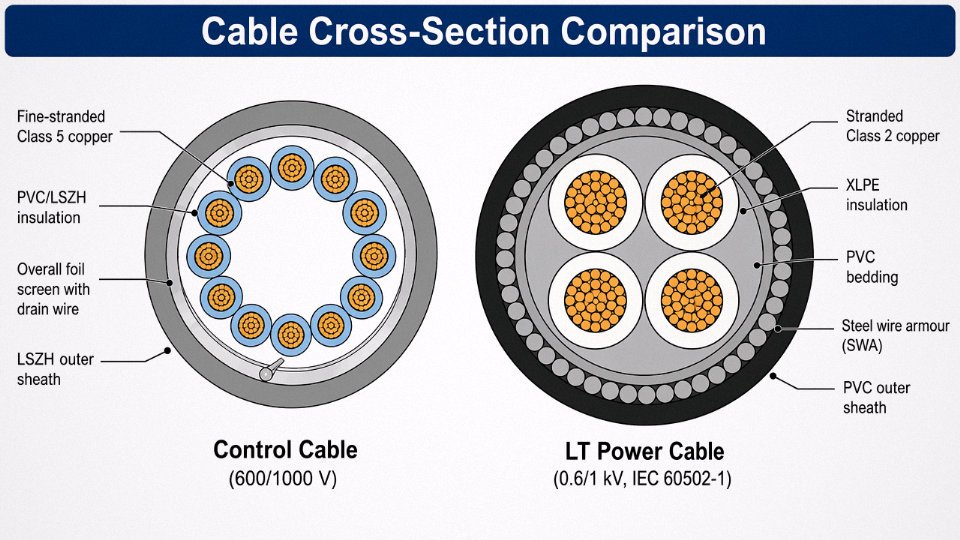
The fastest way to tell these two cable families apart is to cut a cross-section and look at what’s inside. The differences aren’t cosmetic — they trace directly back to what each cable is asked to do for the next 25 years.
Conductors
Control cables are built for flexibility and signal integrity, not bulk current. Most designs spec Class 5 or Class 6 fine-stranded copper per IEC 60228 — sometimes 30 or more individual strands twisted into each core — because the cable gets routed through cable trays with tight bends, terminated repeatedly at DIN-rail terminals, and occasionally re-dressed during panel modifications. Cross-sections run from around 0.5 mm² up to roughly 10 mm², and in practice most instrumentation and control wiring sits between 0.75 mm² and 2.5 mm².
LT power cables are engineered for a completely different constraint: moving large amounts of current continuously without overheating. Class 2 stranded copper is the workhorse here, and Class 1 solid conductors appear in smaller fixed-installation sizes. Aluminium conductors become economically attractive above roughly 50 mm² to 70 mm², which is why you see AWA aluminium-core cables on longer MV feeder runs even at 0.6/1 kV. The range runs from 1.5 mm² up to 400 mm² and beyond for busbar-replacement applications — a 400 mm² four-core LT cable is a heavy, stiff object that no one is bending around a 100 mm radius.
Insulation
Because control cables operate at low voltage — typically 450/750 V or 600/1000 V — the insulation wall thickness is optimised for mechanical protection and flame resistance rather than dielectric withstand. PVC per IEC 60227 is still common and cost-effective for general-purpose plant wiring, though LSZH compounds have become the default in enclosed buildings and tunnels where smoke toxicity matters. XLPE appears where operating temperature needs to run higher. Walls in the 0.6 mm to 0.8 mm range are typical for small cores.
LT cable insulation is a different conversation. XLPE is the dominant material at 0.6/1 kV because it handles the thermal cycling that comes with variable load profiles — energising a 200 kW motor daily for 15 years stresses insulation in ways that a 4–20 mA signal loop simply never does. EPR is used where flexibility at low temperature or resistance to ozone matters. Insulation walls on a 95 mm² XLPE core will be roughly 1.0 mm to 1.6 mm depending on the standard, engineered to sustain dielectric stress rather than just provide a physical barrier.
Screening and Shielding
This is the most operationally significant structural difference and the one most often ignored during procurement. Control cables running near VFD output cables, bus ducts, or contactor panels pick up radiated and conducted noise that corrupts 4–20 mA loops, thermocouple signals, and fieldbus communications. Individual core screens (foil plus drain wire) or an overall braid or foil screen — sometimes both — are standard features on instrumented control cables. Without screening, a plant running high-power VFDs can see persistent signal noise that looks like a faulty transmitter but is actually a cable selection problem.
LT power cables at 0.6/1 kV do not require electromagnetic screeningTrue
LT cables carry power, not sensitive signals; their insulation and construction is designed for voltage and current handling, not EMI rejection. Screening adds cost and complexity with no functional benefit in a power distribution role.
LT cables don’t need screening and don’t have it.
Armour, Inner Sheaths, and Outer Sheaths
Control cables typically use a laid-up construction with fillers between cores, a binder tape or inner sheath, and a robust PVC or LSZH outer jacket. Some designs add an individual core wrap — a thin insulating tape over each insulated core — to improve stripping ease and reduce inter-core capacitance. Armour is optional and project-specific; SWA (steel wire armour) versions exist for direct burial or high-mechanical-risk routes.
LT power cables almost always include armour as a baseline expectation in industrial and infrastructure projects. SWA is standard for copper conductor cables; AWA is preferred for aluminium conductor cables because it avoids the galvanic corrosion risk of steel against aluminium. The armour serves double duty: it provides mechanical protection against dig-in damage and acts as an earthing conductor path. The outer sheath — PVC or LSZH — protects the armour from corrosion rather than the conductor from voltage stress.
Comparison at a Glance
| Parameter | Control Cable | LT Power Cable |
|---|---|---|
| Conductor class (IEC 60228) | Class 5 or Class 6 (fine-stranded) | Class 1 (solid) or Class 2 (stranded) |
| Conductor material | Copper | Copper or aluminium |
| Typical cross-section range | 0.5 mm² – 10 mm² | 1.5 mm² – 400 mm²+ |
| Voltage rating | 450/750 V or 600/1000 V | 0.6/1 kV (IEC 60502-1) |
| Insulation material | PVC, LSZH, XLPE | XLPE, EPR |
| Insulation wall thickness | Thin (optimised for flexibility and flame performance) | Thicker (engineered for sustained dielectric stress) |
| EMI screening | Foil, braid, or individual core screens — common | Not required, not provided |
| Armour | Optional (SWA available) | Standard (SWA or AWA) |
| Number of cores | 2 to 61 | Typically 1 to 5 |
| Typical overall diameter | 8 mm – 40 mm (varies with core count) | 10 mm – 80 mm+ (varies with cross-section) |
The diameter ranges in that table depend heavily on core count, conductor size, and whether armour is included — a 19-core 1.5 mm² screened control cable and a 4-core 240 mm² SWA LT cable can both have an overall diameter around 40–45 mm, but they have almost nothing else in common. Don’t spec by diameter.
Voltage Ratings, Current Ratings, and Electrical Parameters Compared
The voltage rating is where the two cable families split most cleanly, and getting it wrong in a panel design or a cable schedule tends to produce consequences that show up either at commissioning or — worse — years later during an insulation resistance test that the cable fails.
Control Cable Voltage Classes
Control cables sit in two main rating bands under IEC 60227 and IEC 60245: 300/500 V and 450/750 V, where the first figure is phase-to-earth and the second is phase-to-phase. Some heavier-duty control cables — multi-core screened types used in motor control centres or process plant instrument loops — carry a 600/1000 V designation, which pushes them into territory that looks similar to an LT power cable on a data sheet if you’re skimming quickly. Don’t skim.
The practical signal currents flowing through control cores are modest: typically a few milliamps for 4–20 mA loops, up to perhaps 1–2 A for a relay coil or solenoid output, and rarely more than 5–6 A even in direct-on-line starter control circuits. The insulation system is designed around voltage withstand and flexibility, not sustained thermal loading from high current. That distinction matters enormously when someone on the shop floor proposes to “borrow” a spare control core for a small power feed.
LT Cable Voltage Class and the 0.6/1 kV Boundary
LT (low tension) power cables are standardised at 0.6/1 kV per IEC 60502-1 — 600 V phase-to-earth, 1000 V phase-to-phase. That boundary is the defining characteristic of the low-voltage power distribution class. Everything about the construction, the insulation thickness, the factory test voltages, and the installation rules flows from that rating. A 0.6/1 kV cable can operate on any standard 400/415 V three-phase or 230 V single-phase system with comfortable margin.
Factory high-voltage tests for IEC 60502-1 cables require either 3.5 kV AC or 10 kV DC applied between conductors and between conductor and screen or armour. Control cables, tested at voltages commensurate with their lower rating class, don’t come close to those test levels. If a contractor substitutes a 450/750 V control cable in a 400 V distribution circuit and it passes an initial IR test, that’s not confirmation it’s suitable — the dielectric margin is simply inadequate for the service life expected.
Current-Carrying Capacity and Derating
Ampacity for LT cables depends on conductor cross-section, insulation material (PVC versus XLPE makes a meaningful difference), installation method, grouping, and ambient temperature. A 95 mm² copper XLPE cable installed in free air will typically carry somewhere in the range of 270–300 A, dropping to roughly 210–240 A when bunched in a multicore tray with several other loaded cables — the exact figure depends on your grouping factor and the ambient, so always work from IEC 60364-5-52 tables rather than memory.
Control cable cores carry no comparable ampacity rating for sustained use. Treating them as power conductors — even for “temporary” supplies — risks overheating the insulation, degrading the overall cable assembly, and potentially voiding any screening effectiveness if the jacket softens.
Voltage Drop and Impedance Sizing
LT power circuits must be sized so that voltage drop across the cable length stays within 3–5% of supply voltage under full load, which is a real design constraint on long runs to motors or distribution boards. A 185 mm² cable run of 200 m to a large pump motor will have the conductor cross-section partly determined by voltage drop, not just ampacity.
Control cables have no equivalent constraint. Signal integrity in a 4–20 mA loop is maintained by the transmitter and receiver electronics, and a PLC digital output doesn’t care about millivolt drops across a 1.5 mm² core.
Short-Circuit Withstand
LT power cables must be sized to withstand prospective fault current using the adiabatic equation from IEC 60364, ensuring the conductor doesn't overheat before the protective device clears the fault.True
IEC 60364-5-54 and IEC 60364-4-43 require that the minimum conductor cross-section satisfies S ≥ (I × √t) / k, where I is fault current, t is disconnection time, and k is a material constant. This is a mandatory check in any LV power distribution design.
For a 400 V distribution circuit with a prospective short-circuit current of, say, 15–20 kA at the board, the minimum conductor size for fault withstand can actually exceed the size needed for normal load current — particularly on short cable runs where impedance doesn’t limit the fault current much. Control cables carry signal-level currents and have no meaningful fault current to withstand. The protection on a control circuit is typically a 2 A or 6 A fuse or MCB, and the cable is never going to see currents that require an adiabatic calculation.
The practical upshot: cable selection for LT circuits requires three parallel checks — ampacity, voltage drop, and fault withstand. Control cable selection requires essentially none of those. That asymmetry is easy to forget when you’re under schedule pressure filling in a cable schedule at midnight, but it’s the asymmetry that drives everything else in how these two cable types are specified and procured.
Applicable International Standards and How They Govern Design and Testing
Standards aren’t bureaucratic paperwork. On a real project, the standard cited in your purchase order is what the factory builds to, what the third-party inspector checks against, and — if something fails — what the insurance adjuster reads first. Getting the standard wrong at the specification stage means you may receive a cable that is perfectly compliant with a document you never intended to invoke.
IEC Standards Governing Control Cables
The two core documents for PVC- and rubber-insulated control cables are IEC 60227 and IEC 60245 respectively. IEC 60227 covers PVC-insulated cables for fixed wiring up to 450/750 V, and it governs things like minimum insulation thickness at each conductor cross-section and the specific compound grades permitted. IEC 60245 does the same job for rubber insulation — relevant when you’re specifying cables for higher ambient temperatures or more aggressive flexing duty.
Neither of those documents touches fire performance, which is handled separately. IEC 60332-1 covers the single-wire vertical flame test; IEC 60332-3 (with sub-parts A through D) addresses bunched cables installed in cable trays, which is the relevant test once you have a real cable ladder loaded with a dozen or more circuits. Plants where a cable-tray fire could propagate to a control room almost always specify IEC 60332-3-24 (category C) as a minimum. For projects where smoke is the hazard — tunnels, offshore platforms, enclosed substations — IEC 61034-2 sets limits on smoke density during combustion. And if you’re writing a LSZH (low-smoke zero-halogen) spec, IEC 60754-1 and -2 govern the halogen acid gas and corrosivity tests. Specifying “LSZH” without naming 60754 leaves a gap a less-scrupulous supplier will drive through.
IEC Standards Governing LT Power Cables
IEC 60502-1 is the document for LT power cables rated 0.6/1 kV — it covers design, dimensions, test methods, and marking. It references IEC 60228 for conductor construction, which defines Class 1 (solid), Class 2 (stranded), Class 5 (flexible), and Class 6 (highly flexible) conductors. The class matters more than people realise: a Class 2 stranded conductor and a Class 5 flexible conductor can have the same nominal cross-section but very different crimping and termination requirements. Spec the wrong class for a panel-wiring application and your assembler will be fighting the cable every time they try to land a termination.
For armoured variants — SWA or STA — IEC 60502-1 includes mechanical tests such as crush resistance and impact that don’t appear in control cable standards. Those tests exist because power cables take physical abuse during installation that a screened multi-core control cable in a conduit simply doesn’t face.
National Standards and Where They Diverge
BS 6346 (PVC SWA) and BS 6724 (LSZH SWA) are the UK equivalents and remain widely specified across former British territories. They align broadly with IEC 60502-1 in electrical performance but have some differences in armour wire dimensions and test sequences. South Africa’s SANS 1507 and India’s IS 1554 Part 1 are similarly IEC-derived but include local modifications — IS 1554, for instance, has historically specified slightly different PVC compound grades than IEC 60502-1 does. Australia and New Zealand use AS/NZS 5000 series, which again tracks IEC but adds requirements around sunlight resistance and, in some parts, different ampacity tables calibrated to local ground temperatures.
If you’re shipping cable into multiple markets from a single production run, reconciling these national variants is genuinely painful. The safest procurement approach is to list IEC as the primary standard and then call out specific national deviations as addenda.
Reading a Cable Marking String
IEC 60502-1 and IEC 60227 both mandate that cables carry a legible marking at regular intervals — typically every 500 mm to 1 m — that identifies the voltage rating, number and cross-section of conductors, insulation material, and the manufacturer. A marking string like 0.6/1 kV 3×95+1×50 mm² XLPE/PVC tells you the system voltage, the three-phase plus neutral configuration with asymmetric sizing, and both insulation and sheath materials. On control cables you’d see something like 450/750 V 12×1.5 mm² PVC. Knowing how to read these strings quickly — without digging for a datasheet — saves real time during goods-in inspection, especially on projects receiving mixed deliveries from multiple cable types.
Jinda's control and LT power cables are manufactured in compliance with IEC 60502-1, IEC 60227, and IEC 60228, with certifications independently verified by SGS, Bureau Veritas (BV), and CE conformity assessment, making them directly citeable in international project technical specifications.True
Jinda holds third-party certifications from internationally recognised bodies including SGS and Bureau Veritas, which conduct factory audits and product testing against IEC standards — these are verifiable through certificate numbers available on request, consistent with normal practice for export-oriented cable manufacturers supplying projects in Europe, the Middle East, Africa, and Southeast Asia.
For procurement managers writing technical data sheets: cite the specific IEC part number, the national standard if applicable, and the required test certificates by issuing body. Vague references to “international standards” are not enforceable.
Installation Environments and Routing Rules: Segregation, Containment, and Interference Prevention
Getting the cable laid correctly matters just as much as specifying the right cable in the first place. A correctly rated LT power cable run side-by-side with an unscreened control cable in the same tray compartment is, in practice, a noise injection problem waiting to happen — and when it does, the fault rarely points back to the routing decision. It usually shows up as intermittent PLC faults, erratic sensor readings, or nuisance trips, months after commissioning.
Why Segregation Is Mandatory, Not Advisory
IEC 60364-5-52, NFPA 79, and most national electrical installation codes treat physical separation between power cables and instrumentation or control cables as a hard requirement, not a guideline. The mechanism is straightforward: an LT cable carrying 100–400 A produces a magnetic field that inductively couples into adjacent low-level signal circuits. Capacitive coupling adds a second noise path for high-frequency transients — VFD output cables are particularly aggressive here, and any control cable running parallel to a VFD feeder without a metallic barrier is genuinely asking for trouble.
In practice, the severity depends on cable length (parallel runs over roughly 10–15 m are where problems usually start), signal type (4–20 mA loops are more resilient than thermocouples or pulse signals), and whether the control cable has an overall screen bonded at one end.
Separation Distances and Tray Dividers
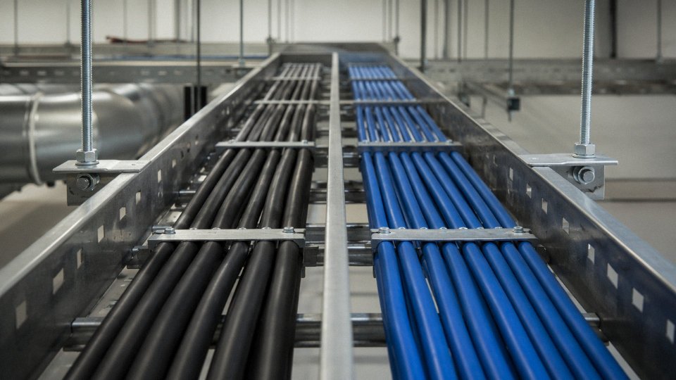
Typical industry guidance — derived from IEC 60364-5-52 and widely adopted in petrochemical and automotive plant standards — specifies a minimum of 200–300 mm clear separation in open cable tray between LT power cables and control or instrumentation cables. The exact figure depends on the signal sensitivity and whether screening is present. A screened, twisted-pair control cable in a properly bonded metallic tray can tolerate closer proximity; an unscreened multiconductor cable cannot.
Where separation distance isn’t physically achievable — and in dense cable basement areas it often isn’t — a continuous metallic divider within a shared tray provides an acceptable alternative. Solid steel dividers outperform perforated ones for high-frequency EMI. Where cables must cross, routing them at 90° rather than parallel minimises mutual inductance coupling to a brief, low-energy interaction rather than a sustained inductive relationship.
Conduit and Tray Fill
LT power cables generate heat under load, and fill ratio compliance isn’t bureaucratic box-ticking — it’s a thermal derating issue. IEC 60364-5-52 fill and grouping factors can reduce the allowable current capacity of a bundled LT cable by 30–50% depending on how many cables share a conduit or enclosed tray section. That has to be built into the cable sizing calculation upfront, not corrected on-site with upsized breakers.
Control cables in multiconductor bundles are less thermally critical at their typical current levels — signal currents of a few milliamps don’t generate meaningful heat — but fill rules still apply for a different reason: maintenance access and future pulling. A tray packed to 80%+ fill makes pulling a replacement cable a half-day exercise in frustration.
Underground and Direct-Burial Routing
For direct-buried LT cables, steel wire armour (SWA) or double steel tape armour is the standard specification. Typical burial depth for LV power cables runs 600–750 mm to finished grade, though road crossings and areas subject to mechanical disturbance normally require 900 mm or a duct. Bedding in sharp-free sand or selected fill, plus warning tape 150–200 mm above the cable, is basic good practice that surprisingly often gets skipped on fast-track projects.
Screened control cables running outdoors or underground need moisture-resistant outer sheaths — PVC is serviceable in most climates, but in areas with sustained ground moisture or aggressive soil chemistry, PE sheathing is worth specifying. Armoured screened control cable is available and makes sense for long outdoor runs where rodent damage or ground movement is a real risk.
Direct burial of LT cables at 600–750 mm depth is consistent with IEC 60364-5-52 and widely adopted national standards for LV power distribution.True
IEC 60364-5-52 and regional codes derived from it (including BS 7671 and many national variants) specify minimum burial depths in this range for LV cables, with greater depths required for mechanical risk zones such as roadways.
Fire Performance and LSZH Requirements
Tunnels, offshore platforms, data centres, public transport infrastructure, and high-rise buildings all impose fire performance requirements that go beyond basic cable rating. Both LT and control cables used in these environments typically need to meet IEC 60332-3 (flame propagation), IEC 61034-2 (smoke density), and IEC 60754-2 (halogen emission). LSZH variants of both cable types are standard catalogue products at this point — the cost premium over PVC-insulated equivalents is real but usually modest relative to the overall cable budget, and specifying it upfront is far simpler than substituting materials after a fire safety audit.
Colour Coding and Core Identification
IEC 60446 governs power core colour identification. For LT three-phase cables, the convention is brown, black, and grey for line conductors with green-yellow for the protective earth. Single-phase adds blue for neutral. This matters at the termination end, not just for installation elegance — incorrect phase identification during switchboard termination is one of the more common commissioning errors.
Control cables take a different approach. Multiconductor control cables — particularly those with 7, 12, 19, or more cores — are typically identified by sequential core numbering printed directly on the insulation, or by a defined colour sequence that repeats in groups. The exact scheme varies by standard and manufacturer. Whatever the system, the critical point is that the numbering or colour sequence must be consistent end-to-end and documented in the termination schedule. On a cable with 24 or more cores, working from memory at the field junction box is where transposition errors happen.
Selection Criteria and Decision Framework for Specifying the Correct Cable Type
Most specification errors happen not because engineers don’t know the definitions, but because they skip a structured decision sequence and rely on habit or what was used on the last similar job. The six-step framework below is designed to be applied in order — each step either resolves the question or narrows the remaining choices.
Step 1 — Define the Circuit Function First
Ask one question: does this circuit deliver load current to an end device (motor, heater, lighting panel, socket outlet), or does it carry a signal, command, or measurement — 4–20 mA, 24 V DC digital I/O, thermocouple, pulse output?
If load current: you need an LT power cable.
If signal or command: you need a control cable.
That single question resolves roughly 90% of cases in practice. The remaining 10% are edge cases — small power feeds to field instruments, solenoid valve actuators drawing under 2 A, or hybrid cables in tight skid packages. Those get resolved in steps 2 and 3.
Step 2 — Determine the System Voltage
Both cable types discussed here cap out below the medium-voltage boundary, so a system nominal voltage above 1 kV automatically takes you to a different product family entirely — MV XLPE or similar.
At 0.6/1 kV: identify whether the circuit is load or signal. A 0.6/1 kV-rated control cable exists (common in IEC projects for marshalling panels), but its core cross-sections are still sized for signal-level currents, not sustained load current. Don’t use it as a budget substitute for a 1.5 mm² or 2.5 mm² power cable just because the voltage rating matches.
Below 500 V: verify actual signal current levels before assuming any small-conductor cable will do. A 24 V DC bus powering 15 parallel solenoids can pull several amps — that changes the conductor sizing conversation entirely.
Step 3 — Calculate Current-Carrying Requirements
For LT cables, run the IEC 60364-5-52 calculation properly. Installation method matters enormously: the same 4 mm² copper conductor derated for a bundled tray in a 50 °C ambient can carry perhaps 60–75% of its free-air rating, give or take, depending on the number of cables grouped and the tray fill. Skipping that derating is one of the more common causes of nuisance tripping and insulation degradation over time.
For control cables, confirm that peak signal current stays within the core’s rated capacity. For 0.5–1.5 mm² cores, typical continuous ratings run roughly 1–6 A depending on installation conditions — more than adequate for instrumentation loops, but worth checking explicitly on solenoid valve or relay coil circuits where inrush can be a factor.
Step 4 — Assess the EMI Environment
Plants running multiple large VFDs, resistance welding equipment, or high-capacity transformers in close proximity generate enough conducted and radiated interference to corrupt unscreened instrumentation signals. If your control cable runs within 300–500 mm of a VFD output cable — or worse, shares a tray with one — specify individually screened pairs or overall screened construction. Earth the screen at one end for analog loops to avoid circulating currents; for digital circuits, both-end earthing is often preferred, but confirm with the instrument supplier’s grounding philosophy.
Unscreened control cables routed parallel to VFD power cables over distances above roughly 10 meters commonly cause signal noise issues in analog instrumentation loops.True
VFD switching frequencies (typically 2–16 kHz) induce capacitive and inductive interference into adjacent unscreened conductors; the effect scales with parallel run length, proximity, and cable spacing — well-documented in IEC 61000 series and in plant troubleshooting practice.
Step 5 — Review the Installation Environment
Temperature range, UV exposure, chemical splash zones, mechanical impact risk, and fire classification each add layers to the construction spec. An outdoor above-ground run in a Gulf coastal environment calls for UV-stabilized, sunlight-resistant sheathing on both cable types. A cable inside a classified hazardous area tray in a refinery may need LSOH (low smoke zero halogen) sheathing per the project fire philosophy. Underground direct burial adds an armoring requirement — SWA or double steel tape for LT cables, and often SWA plus a bedding layer for control cables in the same trench. Don’t treat these as add-ons to be decided during procurement; they belong in the specification from the first revision.
Step 6 — Confirm the Governing Project Specification
General standards like IEC 60502-1 and IEC 60227 set the baseline, but many project owners — oil and gas operators, petrochemical licensors, power generation EPCs — publish their own cable data sheets that specify conductor material, insulation type, sheath color coding, drum length, and test requirements that go beyond the standard. These owner specs override the general standard wherever they conflict. Always pull the applicable project cable specification before finalizing the datasheet, even if you’ve supplied to the same industry sector for years. Requirements vary between operators, and a deviation not caught before manufacturing is expensive to resolve.
Decision Flowchart: From Circuit Function to Cable Selection
START: What does the circuit do?
│
├─► Delivers load current to an end device
│       │
│       └─► System voltage ≤ 1 kV?
│               ├─► Yes → LT POWER CABLE (IEC 60502-1)
│               │           Size by IEC 60364-5-52 with derating
│               │           Add armoring / LSOH / UV rating as environment requires
│               └─► No  → Out of scope (MV cable selection)
│
└─► Carries signal, command, or monitoring data
        │
        └─► EMI risk present? (VFD, welding, large transformers nearby)
                ├─► Yes → SCREENED CONTROL CABLE
                │           Individual screen per pair, or overall screen, or both
                │           Confirm earthing topology with instrument engineer
                └─► No  → UNSCREENED CONTROL CABLE
                            Verify core count (2–61 cores), cross-section (0.5–10 mm²)
                            Add armoring / LSOH / outdoor sheathing as environment requires
Running this sequence on every new cable schedule entry takes perhaps two or three minutes per circuit type — considerably less time than diagnosing a noise-induced measurement drift six months into commissioning, or re-pulling undersized power conductors that trip on overload.
Common Misapplication Mistakes and the Engineering Consequences of Substitution
Walk around enough plants and you’ll see all five of these mistakes. Some cause immediate failures; others take months to surface as degraded insulation, erratic control loops, or a high-resistance joint that only reveals itself during a fault. None of them are theoretical.
Using Control Cable Cores to Carry Power Loads
A 1.5 mm² core inside a multicore control cable looks, on the surface, identical to a 1.5 mm² core in an LT power cable. It is not. Control cable insulation is designed around instrument-level currents — signal voltages, relay coil currents, PLC input loops drawing a few milliamps to a couple of hundred milliamps. When someone connects that core to a 230 V lighting circuit pulling a sustained 10–13 A, the insulation begins accumulating thermal stress it was never rated for. PVC compound on a control cable core typically has a lower cross-linked or thermoplastic grade compared to power cable insulation, and the bundled multi-core construction traps heat. The consequence isn’t always immediate. It can be weeks of gradual degradation before insulation resistance drops, a neutral-to-earth fault develops, and an RCD trips intermittently — or, in poorly protected circuits, a fire.
Control cable conductor insulation is not rated for the sustained current loads typical of 230 V branch power circuits, even where conductor cross-section appears identical to LT cable.True
Control cables are designed to IEC 60228 conductors with insulation specified for low-energy signal and control duties; their thermal current ratings and insulation grades are lower than those of LT power cables rated per IEC 60502-1 for sustained load current.
Unscreened LT Cable for PLC I/O Near Variable-Frequency Drives
This one is common in retrofits where a screened control cable wasn’t available and someone grabbed a 4-core LT cable from stores. Run that unscreened cable parallel to a VFD output for more than a metre or two, and the switching noise — fast-rising voltage edges at 2–10 kHz carrier frequencies, sometimes higher — couples capacitively into the conductors. The result is false signals on analog inputs (a 4–20 mA loop reading 6 mA when the transmitter is sending 4 mA), nuisance trips on digital inputs, and erratic behaviour in proportional valve positioners. Process engineers chase the problem for days assuming a sensor or PLC card fault. The fix is almost always a screened, twisted-pair control cable with the screen earthed at one end only. Drain wire or foil screen — either works, though foil-plus-drain is more practical to terminate reliably.
Assuming Equivalent Flame-Retardant Performance Across Cable Types
Not all cable marked “fire retardant” is equal. IEC 60332-1 covers a single-wire vertical flame test — a very low bar. Bunched cable installations in cable trays, risers, or enclosed spaces on marine vessels require IEC 60332-3C as a minimum, and many public building codes demand IEC 60332-3A. A standard PVC control cable or PVC LT cable in those environments fails the bundled flame test and violates fire safety codes. The practical correction is to specify FR or LSZH cables with the explicit IEC 60332-3 category on the purchase order — not just “flame retardant.”
Mixing Aluminium and Copper Termination Hardware
Aluminium-conductor LT cables cost less per metre for large cross-sections, which makes them attractive for long LV distribution runs. The risk appears at the termination. Aluminium oxide forms on conductor surfaces within hours of exposure to air, and that oxide layer is resistive. Connecting an aluminium conductor into a copper-only compression lug without anti-oxidant compound and proper torque causes a high-resistance joint that heats under load, eventually failing with enough energy to damage switchgear. Aluminium conductors require bi-metallic lugs or aluminium-rated lugs, joint compound applied before crimping, and torque values followed exactly — typically 20–50 Nm depending on lug size, but always defer to the lug manufacturer’s table.
Omitting Armour Earth Clamps on SWA Terminations
Steel wire armour on LT cables serves a dual function: mechanical protection and, critically, a protective earth conductor in the fault loop. On a properly terminated cable, the armour is clamped and bonded at both ends. Skip the armour earth clamp — sometimes done to save time or because the right gland wasn’t in stock — and you’ve defeated the fault protection. Under a line-to-armour fault, the armour cannot carry fault current back to the source, the circuit breaker doesn’t see enough current to trip promptly, and the armour becomes live. This is not a marginal compliance issue. It is a lethal hazard.
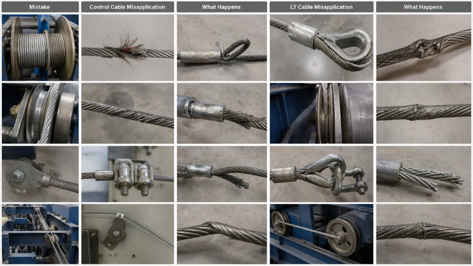
Quick-Reference: Mistakes to Avoid
| Mistake | Likely Consequence | Corrective Action |
|---|---|---|
| Control cable cores used as power conductors | Insulation overheating, degradation, fire risk | Use LT power cable rated for load current; verify ampacity against IEC 60502 |
| Unscreened LT cable for PLC I/O near VFDs | False signals, nuisance trips, erratic control loops | Specify screened twisted-pair control cable; earth screen at one end |
| Assuming all cables meet IEC 60332-3C flame performance | Code violation in bundled installations; fire propagation risk | State IEC 60332-3 category explicitly on specification and PO |
| Aluminium conductors terminated with copper-only lugs | Galvanic corrosion, high-resistance joint, overheating | Use bi-metallic or aluminium-rated lugs with anti-oxidant compound and correct torque |
| SWA armour not earthed at terminations | Armour becomes live under fault; protection device fails to trip | Install correct armour earth clamps and bond armour at both cable ends |
Frequently Asked Questions About Control Cables and LT Cables
Can a control cable be used as a low-voltage power cable in an emergency?
Not as a like-for-like substitute — and “emergency” is exactly the situation where this shortcut tends to create the next, larger problem. Control cable conductors are sized for signal and supervisory currents, typically milliamps to a few amps at most. Run 20–30 A of continuous load current through a 1.5 mm² control cable core and the thermal limits of both the conductor and its insulation are breached quickly. PVC-insulated control cable is generally rated to 70°C conductor temperature; sustained overload pushes that boundary within minutes under full load. Beyond thermal damage, substituting a control cable into a power circuit without re-rating the protection device creates a compliance gap that no insurance adjuster or safety inspector will overlook. In practice, if you are genuinely short of cable on a live project, derate aggressively, document the temporary measure formally, and replace it at the first scheduled shutdown. Never treat the temporary installation as permanent.
A control cable rated 450/750 V can be safely used long-term as a substitute for a 0.6/1 kV LT power cable of the same conductor size.False
Voltage class aside, control cables are not designed for the sustained current-carrying capacity, short-circuit thermal withstand, or protective conductor requirements expected of LT power cables. The insulation system, core identification, and testing regime differ, making direct substitution non-compliant under IEC 60364 and most project specifications.
What does the 0.6/1 kV rating on an LT cable actually mean in practice?
The notation is phase-to-earth voltage / phase-to-phase voltage. So 0.6 kV is the maximum continuous voltage any single conductor should sustain relative to ground, and 1 kV is the ceiling for conductor-to-conductor voltage in a three-phase system. Both limits apply simultaneously in service — you cannot trade one against the other. On a standard 400 V three-phase distribution system, neither limit is approached under normal conditions, which is why 0.6/1 kV cables have comfortable headroom for transient overvoltages and switching surges on industrial networks.
Is XLPE insulation always better than PVC for LT cables?
Depends heavily on the installation. XLPE gives you a 90°C continuous conductor temperature rating versus roughly 70°C for standard PVC, meaningfully better derating performance in hot ambient conditions — think cables buried in poorly ventilated cable basements or routed through process areas above 40°C. Chemical resistance is also superior with XLPE, which matters in petrochemical or water treatment environments. The trade-off is cost, typically 15–30% higher depending on conductor size and market conditions, and slightly stiffer handling during installation in cold weather. For a simple air-conditioned switchroom feeder, PVC is often perfectly adequate and the cost saving is real.
How many cores can a control cable have, and is there a standard core count?
IEC and BS standards accommodate configurations up to 61 cores in a single cable. On most projects, the practical workhorses are 4, 7, 12, 19, 27, and 37-core variants — these align with standard drum lengths, standard gland sizes, and the I/O counts of common field devices like MCC control circuits, valve actuators, and instrument junction boxes. The specific core count you specify should follow your instrument and electrical I/O schedule directly; avoid the habit of rounding up by a large margin “for spares” because a 37-core cable in a 20-core application adds unnecessary weight, cost, and termination labour.
What is the difference between a screened control cable and an instrumentation cable?
Instrumentation cable is essentially a sub-category of screened control cable, with a more demanding screening architecture. Where a standard screened control cable may carry an overall copper braid or foil screen to block external interference, instrumentation cables use individually screened pairs or triads — each signal pair wrapped in its own foil with a drain wire — specifically to suppress pair-to-pair crosstalk. This matters enormously on 4–20 mA analogue loops and thermocouple circuits, where a few millivolts of induced noise from an adjacent pair can represent a meaningful process measurement error. For digital on/off control signals, an overall-screened control cable is usually sufficient; for analogue signals anywhere near power cabling, individually screened instrumentation cable is worth the cost.
Does armour on a cable automatically mean it is an LT power cable?
No. Armoured control cables are a common and entirely legitimate product, used wherever mechanical damage risk is present — direct-buried runs between field instruments and junction boxes, cable routes through heavily trafficked cable trenches, or installations in areas where forklift or equipment movement is a real hazard. The armour type (steel wire armour, steel tape armour, aluminium wire armour) describes mechanical protection; it says nothing about whether the cable carries power or signals. Always read the full cable designation, not just the presence of armour, before assuming application type.
How should I specify Jinda cables for an international project requiring IEC compliance?
Give the technical team the full specification package: cable designation code or equivalent description, voltage class (e.g., 0.6/1 kV), conductor material (copper or aluminium), nominal cross-section in mm², insulation type (PVC or XLPE), armour type if required, outer sheath material, and the specific IEC standard number you are working to — IEC 60502-1 for LT power cables, IEC 60227 or IEC 60245 for PVC or rubber-insulated control cables, and so on. With that information, Jinda’s technical team can confirm the matching product from the catalogue, advise on available certifications, and provide test reports relevant to your project’s approval process. Sending only a vague description or a competitor’s part number wastes everyone’s time and risks receiving a cable that needs re-qualification on site.
Procurement, Supply Chain, and Quality Assurance Considerations for Bulk Cable Orders
Getting the technical specification right is only half the job. The other half — the part that actually determines whether cable arrives on site at the right time, in the right lengths, with paperwork that satisfies a third-party engineer — lives in procurement. Plenty of projects have stalled not because the wrong cable was specified, but because the right cable was specified too late, or without enough commercial detail to get a clean purchase order processed.
Drum Lengths, Cut Tolerances, and Minimising Mid-Run Joints
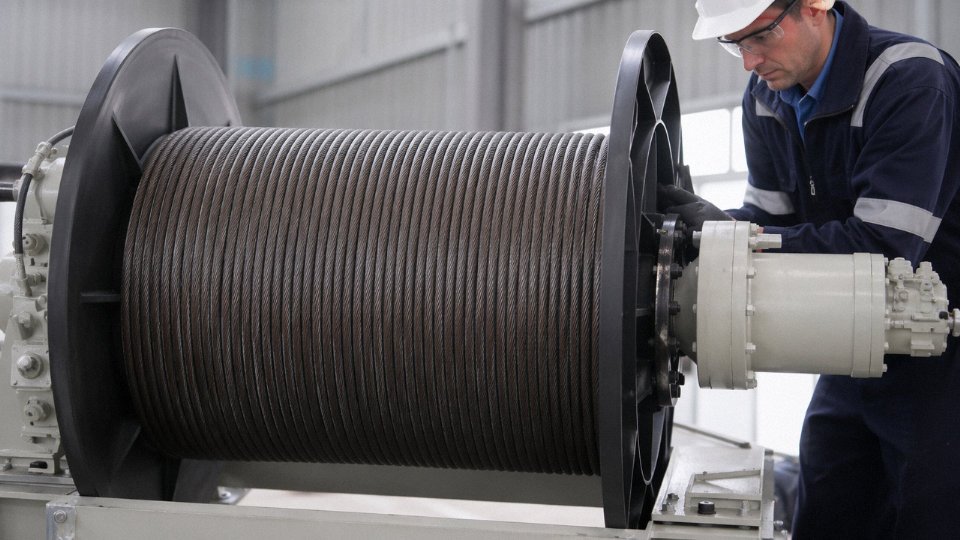
Standard LT power cable is typically supplied on drums of 500 m or 1,000 m, though specific drum sizes can be agreed for large-volume orders. Control cable is more commonly offered in 100 m or 500 m coils, depending on conductor cross-section and core count — a 61-core screened cable on a 500 m coil is a physically large reel, and some manufacturers will push back on that unless the order justifies the setup. Buyers should always specify both a minimum cut length and a maximum cut length in the purchase order. Vague requirements like “cut to length as required” tend to generate short offcuts that get invoiced but sit in a storeroom indefinitely, and worse, they create pressure to make mid-run joints in locations where you really don’t want them. A joint in an LT feeder buried under a cable tray support bracket is a maintenance headache waiting to happen. State your lengths clearly upfront.
Third-Party Inspection and Factory Acceptance Testing
For projects above a certain contract value — roughly speaking, anything where the cable line items run into six figures USD or higher — it is worth building factory acceptance testing (FAT) into the contract. Specify witness testing for conductor resistance per IEC 60228, insulation resistance, high-voltage withstand, and physical dimension checks against IEC 60502-1 or whichever standard governs the order. Experienced buyers nominate a third-party inspection agency (SGS and Bureau Veritas are the commonly used names in this space) to attend at the manufacturer’s facility before shipment releases. This catches dimension nonconformances and resistance drift issues before the cable is on a vessel, not after it has cleared customs and been cut open on site.
Documentation Package — Know What You Need Before You Issue the RFQ
Internationally funded projects, EPC contracts, and government infrastructure work almost always require a formal documentation package: type test reports, routine test reports, material certificates (mill certs confirming copper purity and conductor grade), a Declaration of Conformity, and country-of-origin certificates for customs and tariff purposes. Some Middle Eastern and European project owners now also require RoHS compliance declarations and conflict-minerals statements. The practical advice here is to confirm documentation availability at the RFQ stage, not at order placement. Chasing a mill certificate retrospectively from a manufacturer who outsources conductor rod sourcing is a genuinely painful experience.
Jinda provides full documentation packages including IEC test reports, copper mill certificates, Declaration of Conformity, and country-of-origin certificates for export orders.True
This is standard practice for an established cable manufacturer supplying international EPC and infrastructure projects, and consistent with the company's stated export capabilities across 50+ countries.
Lead Times — The Number Planners Most Often Underestimate
XLPE armoured LT cables in large cross-sections — 185 mm², 240 mm², 300 mm² and above — are not warehouse stock items at most manufacturers, including large ones. High-core-count screened control cables (say, 37-core or 61-core with overall screen and LSZH sheath) fall into the same category. Realistic manufacture lead times for these products run 4 to 10 weeks from confirmed order, depending on raw material availability, current production loading, and any special testing requirements. Copper price volatility adds another wrinkle: manufacturers are reluctant to hold firm pricing on conductor-heavy products for more than 30 days, so project planners who leave cable procurement until late in the engineering phase often find themselves either paying spot-price premiums or compressing a 6-week lead time into 3 weeks at extra cost.
How Jinda Supports International Project Procurement
Shandong Jinda Special Cable Group operates five production bases across China with a combined 470,000 m² of manufacturing space, which gives genuine flexibility to allocate production capacity across product types simultaneously — useful on EPC projects where LT feeders, control cables, and instrumentation cables are all needed on roughly the same delivery schedule. The technical support team can review a cable schedule, flag substitution options where a specified type isn’t producible within the project timeline, and arrange factory tours for major clients evaluating a long-term supply relationship. For buyers new to sourcing from China, that kind of pre-order engagement tends to surface problems — ambiguous specs, conflicting standards references, missing documentation requirements — before they become contract disputes.
Sustainability and Compliance Documentation
Halogen-free LSZH sheathing is no longer a niche request. European and Middle Eastern project owners increasingly specify it as standard for indoor and tunnel installations, and some now ask for Environmental Product Declarations or at minimum a written statement of halogen-free compound sourcing. RoHS compliance is essentially baseline for any cable going into CE-marked equipment assemblies. Ask for these declarations at the RFQ stage and make them a contractual deliverable — a responsible supplier will have them ready without difficulty.