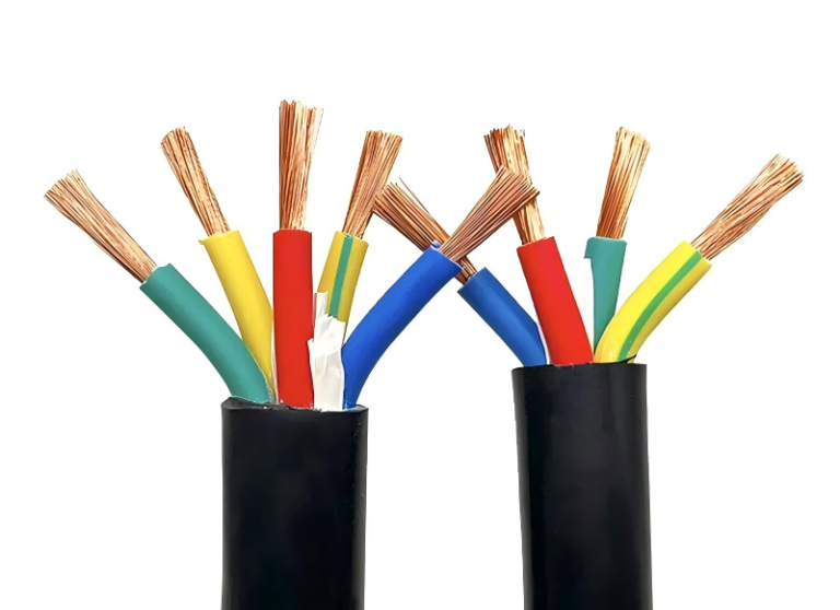
Misidentify a control wire during a panel modification and the consequences stack up fast: a maintenance tech traces the wrong conductor, resets the wrong interlock, and a machine restarts mid-clearance. Best case, you scrap an hour of troubleshooting and reopen the permit. Worst case, you’re writing an incident report. Color coding exists precisely to prevent this, but the standard changes depending on which country the panel was built for, which code the customer’s engineering spec invokes, and sometimes which decade the original electrician trained in.
Control wire colors depend on the applicable standard. IEC 60446 (used across Europe and most export markets) specifies brown for line, blue for neutral, and green/yellow for protective earth. NFPA 79 and NEC Article 409, which govern North American industrial machinery, call for black or red on ungrounded AC control conductors, white or gray for grounded conductors, and green or bare copper for equipment grounding. These two systems are not interchangeable.
What makes this genuinely complicated in practice — and what most wiring guides skip over — is that a single facility can legally contain panels built to both standards, especially after acquisitions, equipment imports, or multi-origin capital projects. Knowing the rule is step one. Knowing which rule applies to the cabinet you’re standing in front of is the part that actually keeps people safe.
IEC 60446 and European Control Wire Color Standards Explained
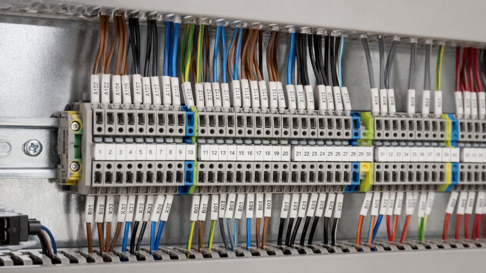
IEC 60446 is the foundational document governing conductor identification by color and alphanumeric marking across low-voltage electrical installations and industrial control systems. It doesn’t just suggest colors — it sets out a system of identification that has to be unambiguous under the worst shop-floor conditions: dim lighting, bundled cable runs, contractors from three different countries working the same panel. The 2007 harmonization update, which was rolled into IEC 60445 as an integrated standard by 2010, replaced the older European scheme where three-phase conductors ran brown, black, and red. That old arrangement caused real confusion when British and Continental European practices met on the same installation. The new sequence — brown for L1, black for L2, gray for L3 — aligned Europe under a single system and made it the default for any equipment exported to or installed within the European Economic Area.
Mandatory Color Assignments and Where They Actually Apply
The hard rules under IEC 60446 are these: green-yellow bicolor exclusively for protective earth (PE), blue for neutral (N), and brown as the single-phase line conductor. In three-phase power wiring the L1/L2/L3 sequence goes brown, black, gray. None of these are interchangeable. The green-yellow combination is so strictly reserved for PE that using it on any other conductor — say, a spare core in a multi-core run — is a genuine safety violation, not a paperwork technicality.
Control panel wiring is where things get slightly more nuanced. Inside an IEC-compliant panel, the same color logic carries over, but you’re usually working with conductors that serve discrete signal and relay functions rather than load-side power. The blue neutral reference stays consistent. Brown or sometimes red appears on the switched live side feeding relay coils and solenoid valve drivers. In practice, many German and Scandinavian panel builders use black extensively for internal AC control wiring distinct from the incoming power conductors — technically permitted under the standard’s allowance for AC control circuits, though it demands clear labeling at terminals.
24 VDC Control Circuits and Hazardous Area Wiring
For 24 VDC control loops, which dominate modern PLC-based systems, IEC convention assigns blue to the negative (0 V) rail and brown or red to the positive (24 V) rail. This isn’t always enforced with the same rigor as the PE green-yellow rule, but it’s the expected convention on any IEC-built machine. Mixing these up creates troubleshooting headaches that cascade: a technician measuring continuity on a blue wire expecting 0 V reference who finds 24 V is going to lose time, and in a live panel that’s a fault-risk too.
For intrinsically safe circuits in Zone 1 or Zone 2 hazardous areas, IEC 60079-14 specifies orange as the designated identification color. This is non-negotiable on certified installations — orange immediately signals “treat this circuit differently” to anyone working near Ex-rated equipment.
IEC 60446 prohibits the green-yellow bicolor combination from being used on any conductor other than protective earth.True
IEC 60446 (and its integrated successor IEC 60445) explicitly reserves the green-yellow bicolor exclusively for protective earth conductors. Using it on any other function violates the standard and creates a genuine shock and fault-identification hazard.
The Alphanumeric Alternative for Dense Multi-Core Cables
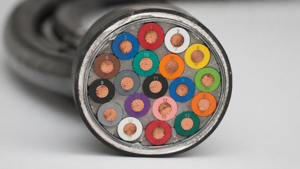
Once you get beyond five or six cores, unique color assignment breaks down practically. A 19-core or 24-core control cable simply cannot carry a distinct color per conductor without reusing combinations — which defeats the purpose. IEC 60446 accommodates this with a numbered sequence system: conductors are identified by printed numbers on the insulation, running sequentially from 1 upward. Common core counts with standardized numbering include 5, 7, 10, 12, 19, and 25-plus core cables. The outer sheath and the PE core (still green-yellow) remain color-coded; everything else is numeric. Ferrule and terminal labeling then carries the identification job.
| Conductor Function | IEC 60446 Color | Approximate Color Reference | Common Control Applications |
|---|---|---|---|
| Protective Earth (PE) | Green-Yellow bicolor | — | Panel ground bar, motor frames, enclosure bonding |
| Neutral (N) | Blue | ~Pantone 279 C | AC supply neutral, 0 V DC reference rail |
| Single-phase Line | Brown | ~Pantone 476 C | AC control supply live, relay coil feeds |
| L1 (three-phase) | Brown | ~Pantone 476 C | Incoming power phase 1 |
| L2 (three-phase) | Black | — | Incoming power phase 2 |
| L3 (three-phase) | Gray | ~Pantone Cool Gray 8 C | Incoming power phase 3 |
| 24 VDC Positive Rail | Brown or Red | — | PLC output supply, sensor feeds |
| 24 VDC Negative Rail | Blue | ~Pantone 279 C | PLC 0 V common |
| Intrinsically Safe Circuit | Orange | ~Pantone 151 C | Ex-zone signal wiring per IEC 60079 |
| Multi-core numbered cores | Sequential numbers on insulation | — | 7-core, 12-core, 19-core control cables |
CENELEC Adoption Across Member States
Every CENELEC member state has adopted IEC 60446 either directly or through the harmonized EN 60446 designation. Germany, France, the Netherlands, and the Scandinavian countries all treat it as mandatory for new installations. The UK retained equivalent provisions post-Brexit through BS 7671 (the IET Wiring Regulations), which aligned with the IEC scheme back in 2004 and hasn’t reverted since. The practical upshot for procurement and export: any control cable or wired panel destined for Europe needs to conform to this color scheme, or it will fail third-party inspection and potentially create insurance and liability exposure on the installed site. Specifying cables to IEC 60446 isn’t just compliance box-ticking — it’s the baseline that makes cross-border machine installation predictable.
North American Control Wire Colors: NEC, NFPA 79, and UL 508A Requirements
The North American regulatory landscape for control wire colors is layered, and understanding which document governs which situation matters more than most engineers expect — especially when a panel built in one jurisdiction gets shipped to a plant in another.
The Three-Layer Hierarchy
Start with NFPA 70, the National Electrical Code. It sets the baseline for all electrical installations in the US and is adopted by most jurisdictions either verbatim or with local amendments. On top of that sits NFPA 79, Electrical Standard for Industrial Machinery, which narrows the focus to machine tools, packaging lines, assembly equipment, and similar industrial apparatus. Then UL 508A covers the panel enclosure itself — the shop-built industrial control panel as a product. Each layer adds specificity. An engineer who reads only the NEC and stops there will miss NFPA 79’s documentation and consistency requirements, which panel shops get caught on during third-party audits more often than they’d like to admit.
NEC Color Rules in Practice
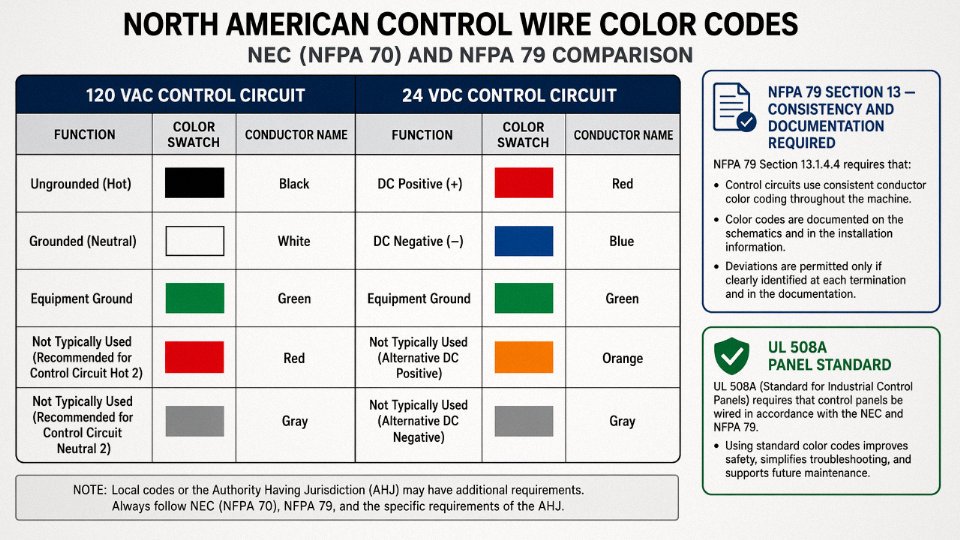
For 120 VAC control circuits — still the dominant control voltage on older North American machinery — the convention is black or red for ungrounded (hot) conductors, white or gray for the grounded conductor (neutral), and green or bare copper for equipment grounding. In practice, most panel builders use black for the primary control leg and reserve red for the secondary ungrounded conductor or for alarm/interlock circuits where visual distinction speeds troubleshooting. White stays as neutral; gray is less common but appears in multi-wire branch circuits where a second neutral is needed and white is already used elsewhere.
The 24 VDC situation is where things get genuinely informal. The NEC doesn’t assign specific colors to DC control conductors beyond grounding requirements. What actually happens on the shop floor is that panel shops have developed their own conventions — orange for 24 VDC positive and blue for 24 VDC negative has become close to a de facto standard across much of the American panel-building industry, driven partly by wire distributors stocking those colors in bulk and partly by shops copying each other’s practices over decades. It works, and it’s readable. But it is not codified in the NEC, so you can walk into a different shop and find white/black or red/black for the same DC circuit. Document it in your wiring diagram and be explicit in your panel specifications if consistency matters across suppliers.
What NFPA 79 Section 13 Actually Requires
NFPA 79 does not hand you a mandatory color chart for every conductor function. What it does require is consistency across the entire machine and clear documentation in the wiring diagram. That means if you choose blue for 24 VDC negative on one panel in a multi-panel line, every panel on that machine needs to follow the same scheme, and the diagram must reflect it. Auditors and inspectors take this seriously. A color scheme that’s internally logical but undocumented fails the standard just as surely as a random one.
NFPA 79 mandates specific wire colors for all control conductors in industrial machineryFalse
NFPA 79 Section 13 requires color consistency and documentation throughout the machine, but does not prescribe colors for every conductor function beyond grounding and grounded-conductor requirements. The specific color scheme is the panel builder's choice, provided it is applied consistently and documented.
Canadian and Mexican Deviations Worth Knowing
Canada is a genuine headache for procurement managers sourcing panels across the border. The Canadian Electrical Code adopted IEC-aligned colors for new installations starting in 2012 — brown for line, blue for neutral, green/yellow for protective earth. Older Canadian plants predate that change and still run black/white/green North American conventions. If you’re retrofitting a line in a mixed-vintage facility in Ontario or Alberta, you can find both color schemes in the same building. Label everything. Don’t assume.
Mexico’s NOM-001-SEDE largely mirrors the NEC in technical substance, which simplifies things somewhat for US panel builders exporting south. The practical complication is documentation: labeling requirements lean toward Spanish-language markings, and international panel documentation packages sometimes miss this, creating headaches during local inspection and commissioning.
Side-by-Side Comparison
| Conductor Function | NEC / NFPA 79 Color | IEC 60446 Color | Conflict Risk on International Shipments |
|---|---|---|---|
| Line / Phase (AC ungrounded) | Black or Red | Brown | High — brown wire read as “safe” by US tech expecting black |
| Neutral / Grounded conductor | White or Gray | Blue | High — blue is DC negative by US convention; confusion is common |
| Equipment grounding | Green or Bare copper | Green/Yellow bicolor | Low — grounding color is consistent across both systems |
| 24 VDC Positive | Orange (industry practice) | No universal standard | Medium — varies widely by shop |
| 24 VDC Negative | Blue (industry practice) | No universal standard | High — blue means neutral in IEC context |
The blue wire conflict is the one that causes real problems. A European-trained technician sees a blue wire and reaches for neutral. A North American tech in a DC panel reaches for blue and expects 24 VDC negative. Neither is wrong by their own standard. That’s exactly why international machinery shipments need explicit color-code documentation in the shipping package, not just in the CAD files back at the engineering office.
DC Control Circuit Wire Colors: 24 VDC, 48 VDC, and High-Voltage DC Systems
DC control wiring is where color-code discipline breaks down fastest on a real plant floor. Unlike AC systems, where IEC 60446 and NFPA 79 give you a reasonably clean framework, DC control circuits sit at the intersection of at least three separate convention families — automation panel builders, telecom-influenced systems, and substation protection engineering — and none of them fully agree. With 24 VDC PLC I/O wiring now essentially universal in modern automation, this is not an academic problem.
24 VDC in European-Influenced Automation Panels
The dominant convention in IEC-aligned automation — Siemens, Beckhoff, Schneider panel builds, most German and Italian OEM machinery — assigns brown (or sometimes red) to the +24 V positive conductor and blue to the 0 V return. PE stays green-yellow, as always.
That blue-for-0V assignment trips up technicians constantly, and understandably so. A maintenance electrician trained entirely on AC systems reads blue as neutral — a grounded conductor sitting at or near zero volts, yes, but one that carries fault current and must never be switched or interrupted carelessly. In a 24 VDC circuit, blue is the 0 V reference rail, which is a different thing conceptually even when the voltage is similar. Probe it carelessly during a live fault trace and you can chase phantom ground faults for an hour before realizing the wiring convention differs from the panel next to it.
North American 24 VDC Panel Practice
Walk into enough North American machine builder shops and you will see at least three different conventions in active use. Many panel builders — especially those with UL 508A listed panels — use orange for +24 V DC and blue for the 0 V return. Others, particularly shops that grew out of older relay-logic traditions, still use red for positive and black for negative DC, mirroring the old automotive and battery-system conventions. A smaller group follows the IEC brown/blue scheme because their OEM parent company is European.
None of these is technically wrong at the facility level, provided the convention is documented and consistent within a panel. The problem is when panels from multiple vendors or multiple project phases live in the same control room. A single MCC room might have orange/blue from one integrator, red/black from another, and brown/blue from a third. That inconsistency is a genuine troubleshooting hazard during an unplanned midnight outage.
NFPA 79 does not specify a mandatory color for the +24 VDC positive conductor in industrial machine wiringTrue
NFPA 79 (2021 edition) specifies colors for ungrounded AC conductors and grounding conductors, but does not mandate a specific color for ungrounded DC positive conductors beyond requiring that grounded DC conductors use white or gray, and that equipment grounding conductors use green or bare. This leaves the positive DC conductor color to the panel builder's convention.
125 VDC and 250 VDC Station Battery Systems
Substation and power plant control panels operate on an entirely different tier of DC voltage, and the stakes rise accordingly. ANSI/NEMA convention for 125 VDC station battery control wiring historically assigns red to the positive DC bus and black to the negative DC bus. This is deeply embedded in North American utility practice — relay protection engineers have worked with it for decades.
The conflict appears when a substation control panel is specified to IEC standards, which typically call for brown positive and blue negative in low-voltage DC circuits. A mixed facility — say, a North American utility installing IEC-compliant protection relays alongside existing ANSI switchgear — can end up with red/black and brown/blue terminating at the same terminal strip. The polarity reversal risk is real. A reversed 125 VDC connection to a protection relay or a DC/DC converter input is not a nuisance fault; it can destroy equipment instantly.
LVDC Grids and EV Charging Infrastructure
The emerging low-voltage DC landscape — building LVDC distribution, EV charging station control circuits, battery energy storage balance-of-plant wiring — is beginning to attract more systematic standardization. IEC 61851 (EV conductive charging) and related IEC TC 69 work are pushing toward more defined color practices for DC conductors, particularly distinguishing positive, negative, and mid-point conductors in bipolar LVDC systems. Expect red for positive, white or gray for mid-point reference, and black for negative to consolidate as a working convention in this space, though it is still far from uniformly adopted as of this writing.
Marking Practice That Actually Holds Up
Color alone is insufficient for DC polarity identification, full stop. Any DC control circuit — 24 VDC, 48 VDC, or 125 VDC — should carry both the wire color convention and alphanumeric sleeve markers (“+24V”, “0VDC”, “125V+”, “NEG”) at every termination point. On multi-core numbered-core cables, print the polarity designation on the terminal block drawing alongside the core number; do not assume the wire color survives the next panel modification or the next technician who replaces a cable pull without checking the drawing.
Ferruled sleeves — the kind you crimp with a standard Weidmüller or Phoenix Contact ferrule tool — cost almost nothing per termination and have prevented more polarity-reversal incidents than most engineers will admit. It is one of those maintenance habits that looks like overhead until the day it is not.
Specialty Control Wire Colors: Intrinsic Safety, Thermocouple, and Communication Cables
Specialty control wiring is where color stops being a convenience and becomes a hard safety or measurement requirement. A general electrician who knows IEC 60446 cold can still cause serious problems in a hazardous area or a temperature loop if they treat specialty cable color conventions as interchangeable with general wiring practice. They are not.
Intrinsically Safe Circuits: Light Blue Is Non-Negotiable
IEC 60079-14 and the ATEX directives require that all intrinsically safe (IS) circuit wiring be identified by light blue — not navy, not standard blue, light blue — throughout the installation, from the IS barrier in the safe area to the field instrument in the hazardous zone. The rationale is straightforward: IS circuits operate at energy levels low enough that they cannot ignite a flammable atmosphere even under fault conditions, but only if the wiring stays segregated from non-IS circuits. Cross-connect a 24 VDC general control wire onto an IS loop and you potentially exceed the permissible voltage or capacitance limits set by the barrier manufacturer, invalidating the protection concept entirely.
In practice this means conduit, cable trays, junction boxes, and terminal strips used for IS wiring must be dedicated and labeled, and the light blue jacket or sleeve must be visible at every termination point. Some plants use light blue cable ties on otherwise standard cables as a shortcut — that approach is technically non-compliant under most ATEX certification audits.
Connecting a standard 24 VDC control conductor to an intrinsically safe circuit can invalidate the ATEX installation certification and create ignition risk in the hazardous zone.True
IEC 60079-14 requires strict energy segregation in IS circuits; introducing non-IS conductors can exceed barrier-specified voltage, current, or capacitance limits, defeating the intrinsic safety protection concept.
Thermocouple Extension and Compensating Cables: Two Systems, Completely Different Colors
This is probably the single biggest source of measurement error I’ve seen in plants that import equipment from one continent and instrument it with locally sourced cable. ISA MC96.1 (ANSI) and IEC 60584-3 assign completely different color codes to the same thermocouple types, and the mismatch is not subtle.
| Thermocouple Type | ANSI Positive / Negative | IEC Positive / Negative |
|---|---|---|
| Type K | Yellow / Red | Green / White |
| Type J | White / Red | Black / Red |
| Type T | Blue / Red | Brown / White |
| Type E | Violet / Red | Violet / Black |
| Type N | Orange / Red | Pink / White |
Reverse-polarity or wrong-type compensating cable produces a temperature error that can be tens of degrees or more depending on the ambient temperature at the junction — enough to cause a process upset, trigger spurious shutdowns, or silently corrupt quality data. The cable outer jacket color also differs between the two standards for the same thermocouple type, which means visually inspecting the jacket alone tells you nothing without knowing which standard was used.
Always specify the standard explicitly in the purchase order and verify the cable markings on receipt.
RTD and Instrumentation Cables
For RTD connections, common industry practice (loosely codified in ISA 50.1 and largely carried by manufacturer convention) uses red and white for 2-wire configurations, red/white/black for 3-wire, and red/white/black/blue for 4-wire. The red conductor is almost universally the excitation lead. These are not as rigorously mandated as thermocouple colors, so cable-to-cable variation between manufacturers is real — verify conductor assignments on the datasheet, not just the color.
Fieldbus and Industrial Communication Cables
Color here functions as a system identifier rather than a conductor polarity marker, which is a different concept worth keeping separate in your thinking.
PROFIBUS PA uses an orange/gray twisted pair per IEC 61158, orange specifically chosen for visibility in industrial environments and to signal “fieldbus, handle carefully.” DeviceNet specifies a thick black trunk cable carrying 24 VDC power alongside data, with thinner white and blue drop cables for node connections — the colors follow the Allen-Bradley / ODVA specification closely enough that a grey-market cable with wrong jacket colors is usually an off-spec product regardless of what the vendor claims. AS-Interface uses a flat, keyed yellow cable that is physically polarized so it cannot be reversed, and the yellow is part of the AS-i system identity globally.
Getting the wrong-colored cable that is otherwise electrically similar will create confusion during commissioning and may fail a third-party system audit.
Fiber Optic Cables in High-EMI Machinery
As fiber-based I/O links push further into machine control — particularly in high-EMI environments around large VFDs, resistance welders, and induction heating systems — control technicians need working knowledge of TIA-598-C fiber color codes. Individual fibers in a 12-fiber array follow the sequence: blue, orange, green, brown, slate, white, red, black, yellow, violet, rose, aqua. Mess up fiber 3 (green) and fiber 11 (rose) during a splice and you may cross two separate control zones with no obvious electrical fault to find.
Why Specialty Cables Need Their Own Line Item on the Purchase Order
Ordering a “blue control cable” when you need IS-rated light blue is a specification failure, not a sourcing shortcut. Each specialty category — IS wiring, thermocouple extension, RTD, fieldbus, fiber — carries specific conductor materials, insulation ratings, shielding requirements, and color conventions that are part of the performance specification, not cosmetic details. A generic substitute may pass incoming inspection visually and still cause a failed hazardous area audit, a chronic measurement offset, or a fieldbus topology that never quite achieves spec-compliant signal integrity. Write the standard, the thermocouple type or fieldbus protocol, and the color convention explicitly. That single line of specificity prevents a category of problems that are genuinely painful to diagnose after installation.
How to Read Multi-Core Control Cable Color Sequences on a Real Cable Drum
Unrolling a 61-core control cable on a busy panel-shop floor while a commissioning deadline looms is exactly the wrong moment to discover you don’t know which core is which. This section is about avoiding that situation before it happens.
The Two Physical Identification Systems You’ll Actually Encounter
Commercial multi-core control cables use one of two approaches, and which one you get depends almost entirely on core count.
For cables with roughly 5 cores or fewer — sometimes up to 7 — manufacturers assign a distinct color to each conductor’s outer insulation. Every core looks different. You can trace core 3 visually across a terminal strip with no sleeves, no label gun, nothing fancy. This works fine at low core counts because the color palette has enough distinct, unambiguous options. Above that threshold, it breaks down fast. Brown, black, gray, and violet start looking disturbingly similar under a sodium vapor lamp at 6 AM.
For 8 cores and up — and this extends to 12, 19, 25, 37, 61 cores or more — the industry standardized on a numbered-core system. All current-carrying conductors share the same base insulation color (almost always black in European practice, occasionally gray), and each core has its identification number printed or embossed directly onto the insulation surface in white or contrasting ink. The protective earth core remains the mandatory green-yellow bicolor, regardless of core count. This is non-negotiable under IEC 60446.
Walking Through a 12-Core Cable: What You Actually Do
Say you’re pulling a 12-core 1.5 mm² screened control cable from a motor control cabinet to a remote I/O station across the plant. The drum label — read it before you cut anything — will reference IEC 60228 for conductor construction and IEC 60446 for color identification. Cores 1 through 12 are black insulation with white printed numerals; core 13 is your green-yellow PE.
Tracing core 7 from one cabinet to the other requires three things working together: the cable schedule (which maps core number to signal function, e.g., core 7 = “conveyor run command”), ferrule end-sleeves stamped with the same numeral installed during termination, and the terminal block labeling system referenced in IEC 60445. Without all three aligned, the numbered cable alone doesn’t protect you. In practice, I’ve seen panels where the ferrules were installed correctly but the cable schedule had been updated for a design revision and nobody reprinted the laminated copy on the cabinet door. The core numbers were right; the signal assignments were wrong. One afternoon of phantom faults resulted.
The HD 308 S2 Color Sequence for Lower Core Counts
For European harmonized cables following HD 308 S2, the first five cores have assigned colors before the numbered-core convention takes over: Core 1 is brown, Core 2 is blue, Core 3 is black, Core 4 is black, Core 5 is gray (sometimes white in older production). From Core 6 onward, black with sequential numbering is standard. This matters when you’re mixing a 5-core feed cable with a 12-core signal cable in the same trunking — the color conventions aren’t the same system, and confusing them creates exactly the kind of ambiguity IEC 60446 was written to prevent.
North American Practice: Conduit Pull vs. Pre-Assembled Cable
American panel shops typically don’t use pre-assembled multi-core cable the way European shops do. Individual THHN/THWN conductors pulled through EMT or rigid conduit is the dominant method, and conductor color is largely governed by whatever the supply house has in stock in the required gauge. A 12-conductor run might use black, red, blue, white, green, orange, yellow, brown, gray, and then striped variants to fill out the count — driven by availability as much as any formal color plan. The panel drawing’s wire list becomes the absolute authority, not the conductor color itself.
In North American industrial panel practice, conductor color in multi-conductor conduit runs is not standardized for signal conductors beyond grounding and neutral requirements, meaning the wiring diagram is the primary identification reference.True
NEC and NFPA 79 mandate specific colors only for grounded conductors, equipment grounding conductors, and ungrounded power conductors. For control signal conductors in conduit beyond those categories, no mandatory color assignment exists, and local practice and drawing conventions govern identification.
Ferrules, Heat-Shrink Sleeves, and Why Color Alone Is Never Enough
In any installation with more than about 10 terminations per cabinet, color identification alone is insufficient. Wire ferrules — either pre-printed plastic sleeves or heat-shrink tubing printed with a label gun — applied at both ends of every conductor are the professional standard. IEC 60445 governs the identification of terminals and conductors at connection points, and it effectively requires unambiguous marking at each termination. The consequence of skipping this step isn’t just slower fault-finding; it’s a maintenance technician three years from now disconnecting the wrong core during a live troubleshooting session.
Practical Identification Method Reference
| Scenario | Recommended Identification Method | Standard Reference | Jinda Cable Product Type |
|---|---|---|---|
| 5 cores or fewer, color-distinct insulation | Full-color outer insulation, no sleeve required | IEC 60446, HD 308 S2 | Multi-core control cable, ≤5 cores |
| 6–61 cores, same base color | Numbered core insulation + ferrule end-sleeves at both terminations | IEC 60446, IEC 60445 | Numbered-core screened control cable |
| North American conduit pull, mixed colors | Panel wiring diagram + ferrule sleeves; color per NEC grounding rules only | NEC Article 409, NFPA 79 | Individual THHN-rated control conductors |
| Intrinsic safety zone, color-critical | Light blue outer insulation on IS circuit cores; maintain full segregation | IEC 60079-14 | IS-rated multi-core control cable |
| High core-count (37+), densely terminated cabinet | Numbered cores + printed cable schedule laminated inside door + end-sleeve ferrules | IEC 60445, IEC 60446 | High-count numbered-core screened cable |
Selecting the Right Control Cable Construction for Your Application
Color compliance gets you past inspection. Construction gets you past five years of operation without a fault.
Once you’ve confirmed your conductor color scheme matches the applicable standard — IEC 60446, NFPA 79, or whichever regional code governs your site — the next procurement decision is arguably harder: specifying the right cable construction for the actual physical environment the cable will live in. A 1.5 mm² brown-insulated conductor in a PVC-jacketed unshielded cable looks identical on a datasheet to the same conductor in an LSZH-jacketed, individually-shielded, Class 5 fine-stranded version. The price difference can run 40–90% depending on construction, and the wrong choice in a drag-chain application or a VFD enclosure will cost far more in downtime than the savings.
Core Count, Cross-Section, and Stranding Class
Most industrial control cables run from 2-core to 61-core, with 4-, 7-, 12-, and 19-core configurations being the workhorses in panel wiring and field instrument loops. Cross-sections typically span 0.5 mm² to 6 mm², though for standard 24 VDC PLC I/O and 120 VAC control circuits, 1.5 mm² and 2.5 mm² cover the vast majority of applications. Go below 0.5 mm² and you’re into instrumentation territory where the cross-section is sized for signal integrity, not current capacity.
Stranding matters more than most procurement specs acknowledge. IEC 60228 Class 1 (solid) conductors are fine for fixed, buried, or conduit installations where the cable never moves after commissioning. Class 2 (stranded) handles normal cabinet wiring. Class 5 (fine-stranded, flexible) is non-negotiable for moving machine applications — energy chains, robot arms, sliding doors, anything with repeated bending cycles. Specified flex life ratings for Class 5 cables in energy-chain service typically fall between 5 and 10 million cycles, though the actual number depends heavily on bend radius, travel speed, and whether the cable has a purpose-engineered flex-rated insulation compound rather than standard PVC. Using a standard Class 2 cable in a drag chain is a slow failure — the conductors work-harden and fracture, usually starting with the outermost conductors in the bundle, and the fault shows up as an intermittent signal that is maddening to trace.
Shielding: When You Need It and How to Ground It
Unshielded multi-core control cable is perfectly adequate for short runs (roughly under 30–50 m, depending on the electrical environment) in low-noise fixed installations. The moment you’re running analog 4–20 mA loops, thermocouple extensions, or control signal cables near VFD output cables or large motor starters, you need shielding. Individual pair shielding isolates each signal channel; an overall aluminum-mylar foil with tinned copper braid drain wire provides mechanical robustness and lower shield resistance. Some instrumentation cables use both — foil per pair plus an overall braid.
One grounding point that catches engineers out: a shield grounded at both ends in a 4–20 mA loop creates a ground loop that can inject more noise than it removes. Single-end grounding at the control panel is standard practice for analog signals. For high-frequency interference near VFDs, both-end grounding with careful equipotential bonding is sometimes necessary. Get this wrong and you’ll spend weeks chasing a “noisy sensor” that turns out to be a shield termination problem.
LSZH Jackets: Performance Difference and Color Implications
Low Smoke Zero Halogen (LSZH, also written LSOH) cable jackets are no longer a niche specification. European tunnel projects, offshore platforms, rail rolling stock, and any public building governed by EN 50267 or IEC 60332-3 flame-spread requirements will mandate LSZH. The practical difference from standard PVC: in a fire, PVC burns and releases hydrogen chloride — corrosive, toxic, and capable of destroying electronics in adjacent panels long after the fire itself is extinguished. LSZH compounds produce significantly lower smoke density and no halogen acids.
LSZH-jacketed cables are required by EN 50267 for control cables installed in European tunnels, offshore facilities, and railway rolling stock.True
EN 50267 and IEC 60332 series standards specify flame propagation and smoke emission limits that standard PVC cables cannot meet. LSZH compound formulations are specifically engineered to comply with these limits and are mandatory under many European project specifications and national building regulations.
One procurement nuance: LSZH compounds don’t take pigments the same way PVC does. The range of available jacket colors is narrower, and some multi-core color sequences that are straightforward in PVC become difficult to source in LSZH. Confirm color availability early if you’re specifying a non-standard core count or a project with a tight color-code requirement.
Armoring and Jacket Options
Mechanical protection — steel wire armoring (SWA) or steel tape armoring (STA) — is the right answer for direct-burial runs, cable trays exposed to mechanical damage, or anywhere a forklift might reasonably be driven. SWA offers better flexibility and tensile strength; STA is lighter and adequate for cables that won’t be pulled under tension. Both add meaningful weight and diameter, which affects conduit fill calculations.
Specification Checklist
| Parameter | Common Options | Governing Standard | Selection Trigger |
|---|---|---|---|
| Core count | 2 to 61 | Project I/O schedule | Number of control points per run |
| Cross-section | 0.5–6 mm² | IEC 60228, NEC | Current load, voltage drop, loop impedance |
| Stranding class | Class 1 / 2 / 5 | IEC 60228 | Fixed vs. flex/moving application |
| Insulation material | PVC, XLPE, LSZH | IEC 60227, EN 50267 | Temperature rating, fire code, chemical exposure |
| Shield type | None / foil / braid / foil+braid | IEC 61000-5 (EMC) | Analog signals, VFD proximity, loop length |
| Jacket compound | PVC, PUR, LSZH, LSZH-PUR | EN 50267, IEC 60332 | Environment, flex life, fire code |
| Armoring | None, SWA, STA | IEC 60502 | Mechanical exposure, direct burial |
| Temperature rating | –20 °C to +90 °C typical range | IEC 60216 | Ambient + self-heating in enclosures |
Jinda’s control cable range covers the main construction families that global industrial projects actually need: multi-core PVC control cables per IEC 60227 and GB/T 9330, LSZH variants, SWA and STA armored types, screened instrumentation cables for analog and thermocouple service, and purpose-built flexible cables for moving machine applications. Supply runs from 100-meter development samples up to full project lots measured in hundreds of kilometers — which matters for large infrastructure projects where mid-project sourcing changes are genuinely painful.
The short version: get the color code right for compliance, then get the construction right for the environment. They’re separate decisions, and conflating them is where expensive mistakes happen.
Common Control Wire Color Mistakes on International Projects and How to Avoid Them
Cross-border machine builds and instrumentation projects are where color-code errors stop being theoretical and start costing real money. The mistakes below are not edge cases — they show up repeatedly on projects that span multiple standards jurisdictions, multiple suppliers, or both.
Mistake 1: IEC-Colored Wiring Inside a UL 508A Panel
A panel shop in Germany wires a machine to IEC 60446 — brown for line, blue for neutral, green-yellow for PE — then ships it to a US customer whose facility requires UL 508A listing and NFPA 79 compliance. During the UL field inspection, the inspector sees brown conductors where NFPA 79 expects black or red for ungrounded AC conductors, and blue where white or gray is required for grounded conductors. The panel fails. Re-wiring on-site in the US, with the machine already partially installed, typically costs several times what it would have cost the German shop to switch color schemes before shipment.
The governing standard is determined by the installation country, not the manufacturing country. Get that in writing during the quotation phase.
Mistake 2: Blue Wire for Both AC Neutral and 0 V DC in the Same Cabinet
IEC 60446 permits blue for both the AC neutral conductor and the negative rail of a DC control circuit. In a mixed AC/DC panel — common on any machine with 230 VAC control relays and 24 VDC PLC I/O — this creates a genuine commissioning hazard. A technician working quickly can connect a 24 VDC device to the AC neutral rail, or worse, reverse polarity on a DC output card. Neither mistake always produces an immediate obvious fault. Some PLC input modules will partially function reversed; others will fail silently or intermittently. The fix is strict supplementary labeling — wire ferrules at every termination, polarity markers on terminal blocks — and ideally a separate color (dark blue or black, depending on plant convention) reserved exclusively for DC negative. Don’t rely on the base color standard alone in mixed-voltage cabinets.
Mistake 3: Mixed Manufacturer Core Color Sequences Mid-Project
A project orders 500 m of 12-core control cable from one manufacturer, then sources a top-up reel from a second supplier to cover a late design change. The first cable starts core numbering with brown; the second starts with black. Every drawing and termination schedule references the first sequence. Technicians working from those drawings on the second cable — often under schedule pressure — terminate incorrectly, and the errors scatter across the installation rather than concentrating in one identifiable area.
A single-source cable supply agreement for the full project quantity eliminates mid-project color sequence mismatches.True
Different manufacturers follow different internal color rotation sequences for multi-core cables; IEC 60446 and IEC 60189 specify individual conductor colors but do not mandate a single universal rotation order for multi-core assemblies, so two compliant cables from two manufacturers may differ.
Jinda’s multi-plant production structure addresses this directly: a large project order can be split across production bases while maintaining the same color sequence, insulation compound batch, and drum-length format throughout, because production parameters are centrally controlled. For procurement engineers, the practical action is to specify the core color sequence explicitly in the purchase order — don’t assume two IEC-compliant cables from different factories will match.
Mistake 4: ANSI vs. IEC Thermocouple Extension Cable Confusion
Type K thermocouple extension cable is a classic ambush on instrumentation projects that mix US and European engineering teams. IEC convention assigns green to the positive leg and white to the negative. ANSI/ASTM convention uses yellow positive and red negative. A technician trained on ANSI convention who terminates an IEC-colored Type K cable with the wires swapped will generate a temperature signal that decreases as actual temperature rises — or produces a reading that is wrong by an amount that depends on the temperature differential between the junction and the head. The transmitter will not alarm. The process historian will log the wrong value. In a temperature-critical process — a heat-treat furnace, a reactor jacket — this can run undetected through an entire shift.
The mitigation is simple and often skipped: include cable color convention (ANSI or IEC) explicitly in the instrument data sheet, and require the commissioning team to verify polarity at each head before loop checks.
Mistake 5: Standard PVC Cable in an ATEX Zone 1 Circuit
Intrinsic safety circuits in ATEX Zone 1 areas require light blue insulation throughout — not just on the IS devices, but on every conductor in the IS loop. Standard PVC control cable in any other color fails third-party ATEX verification, regardless of the cable’s electrical characteristics. Re-pulling cable in an installed and partially commissioned plant is expensive in labor and in schedule. In congested tray runs or conduit systems, it may require dismantling other services. The light blue requirement is not optional and is not satisfied by labeling or tagging.

Pre-Order Control Cable Color Specification Checklist
Eight questions a procurement engineer should answer before placing an international control cable order:
| # | Question | Why It Matters |
|---|---|---|
| 1 | What country is the installation in? | Determines governing standard: IEC 60446, NFPA 79/NEC, or a national derivative |
| 2 | Which certification is required on the finished panel or system? | UL 508A, CE, EAC, CCC, etc. — each may imply specific wiring color requirements |
| 3 | Are circuits AC-only, DC-only, or mixed? | Mixed panels require a documented internal color convention beyond the base standard |
| 4 | Are any circuits intrinsically safe (ATEX/IECEx/NEC 504)? | Mandates light blue insulation on all IS conductors regardless of other standards |
| 5 | Is installation fixed or in a moving/flexing application? | Affects conductor stranding and jacket compound; color stability under flex cycles varies by insulation type |
| 6 | Single-core or multi-core cable? | Multi-core: specify core color sequence by number, not just “IEC compliant” |
| 7 | Is individual or overall screening required? | Screened pairs or overall foil/braid may restrict visible core colors to internal layers only |
| 8 | What flame/smoke performance class is required? | LSZH (low smoke zero halogen) vs. PVC affects insulation color stability at temperature and may be mandated by facility or local code |
Answer all eight before the RFQ goes out. Discovering the answers after delivery typically costs more than the cable itself.
Frequently Asked Questions About Control Wire Colors
What color is the control wire in a standard 120 VAC control circuit?
It depends entirely on which standard governs the installation. In North America — NEC Article 409 and NFPA 79 for industrial machinery — the ungrounded (hot) control conductor runs black, and the grounded conductor is white or gray. Those aren’t suggestions; they’re code. In an IEC 60446 installation (most of Europe, and increasingly the default on export projects shipped to the Middle East or Southeast Asia), the line conductor is brown and the neutral is blue. This trips up technicians all the time on projects where the panel was built to one standard and commissioned in a country expecting the other. If you’re handing off a 120 VAC panel to a plant in Germany, that brown/blue expectation will be in the local electrician’s head regardless of what your drawings say.
What color wire is used for 24 VDC PLC control wiring?
No single universal standard applies here, which is genuinely the honest answer. European panel shops predominantly use brown for the +24 V supply conductor and blue for the 0 V return — effectively borrowing the IEC AC color convention and adapting it to DC. North American integrators often reach for orange on the positive rail and blue on the 0 V side, partly to visually distinguish DC control from 120 VAC black conductors in the same enclosure. Neither approach is wrong as long as it’s consistent throughout every panel in the project and accurately reflected on the wiring diagram. Inconsistency within a single panel — say, half the 24 VDC wiring in red and half in orange because two technicians pulled from different spools — is where troubleshooting calls at 2 a.m. come from.
Why is the ground wire always green or green with a yellow stripe?
IEC 60446 and NEC both reserve green-yellow bicolor and solid green exclusively for protective earth conductors, prohibiting those colors from any other circuit function.True
IEC 60446:2010 clause 5.3 and NEC Article 250 explicitly restrict green and green-yellow to equipment grounding/protective earth conductors. No other conductor function may use these colors under either standard.
The reasoning is straightforward: a grounding conductor that gets mistaken for a signal wire, or a signal wire mistaken for ground, can kill someone or destroy equipment without triggering any obvious fault. Reserving a single globally recognized color — one that’s visually distinct and not close to any phase or neutral color — removes ambiguity in the one circuit where ambiguity is most dangerous. No label, sleeve, or marker overrides this reservation. If you find green wire on a project and it’s not the PE conductor, that’s a non-conformance worth stopping work for.
Can I use any color wire for control wiring as long as I label it?
Labeling alone is not a substitute for mandatory color requirements on PE conductors, neutral conductors, and intrinsically safe circuits. For those three categories, the color is the protection mechanism — not the label. That said, for ungrounded control conductors (the “hot” side of your control logic), many standards do permit deviation from default colors provided the wiring diagram documents the actual colors used and the installation is consistently applied. Always verify against the specific standard for the country of installation. A panel destined for Australia, for instance, needs to satisfy AS/NZS 3000, which has its own nuances compared to straight IEC 60446.
What is the color code for intrinsically safe control wiring?
IEC 60079-14 and the ATEX Directive 2014/34/EU both require that intrinsically safe circuit wiring be identified in light blue — specifically a pale blue distinct from the darker blue used for IEC neutral conductors — along its entire routed length. This applies whether the identification comes from the insulation color itself or from continuous light-blue sleeving applied over another base color. The intent is that anyone working inside an enclosure can instantly distinguish IS circuits from non-IS circuits before touching anything. Accidental connection of non-IS equipment into a certified IS loop can invalidate the entire hazardous area protection concept, and no amount of documentation after the fact fixes that.
How do I identify individual cores in a 19-core or 27-core control cable?
At higher core counts, color alone can’t carry the load. IEC 60446 addresses this practically: cores are given a uniform insulation color — typically black — and each is individually printed with a sequential white number. The protective earth core retains its green-yellow bicolor regardless of core count. In practice, always cross-reference the printed numbers against the manufacturer’s drum label and the test report shipped with the cable. Numbering sequences can occasionally vary between manufacturers, especially on non-standard core counts, and discovering a mismatch mid-termination on a 48-core cable is an expensive way to learn that lesson.
Does Jinda Special Cable Group supply control cables with custom color configurations for export projects?
Yes. Jinda’s five production bases in China manufacture control cables to IEC, BS, AS/NZS, and customer-specific color schemes, with third-party test certification available. Custom core counts, cross-sections, insulation colors, and jacket colors are supported for orders meeting minimum quantity thresholds — the exact MOQ depends on the cable type and construction complexity. Typical lead times and technical requirements are worked out during the inquiry stage, so it’s worth submitting a full technical specification rather than just a core count and voltage rating. Projects with non-standard color requirements — a Gulf Cooperation Council project specifying a regional variant, for example, or a renewable energy installation needing a specific DC cable color scheme — are the kind of procurement challenge Jinda’s technical team handles regularly.
Specifying and Sourcing Control Cables for Global Projects: A Procurement Framework
Getting the color codes right is only half the battle. The other half is making sure the cable you receive on site actually matches what you specified — and that the documentation proves it. Here is a structured sequence that experienced procurement engineers use to avoid expensive surprises.
Step 1 — Establish the Governing Standard Before Writing Anything Else
This sounds obvious. It is frequently skipped anyway, especially on projects where engineering and procurement run in parallel under schedule pressure.
Identify the country of installation and the applicable electrical code first: NEC / NFPA 79 / UL 508A for the United States and much of Latin America, IEC 60364 / IEC 60446 for most of Europe and Asia-Pacific export markets, BS 7671 for the UK, AS/NZS 3000 for Australia and New Zealand, SASO for Saudi Arabia. That single decision cascades into acceptable conductor colors, whether numeric identification is permitted in place of color, insulation voltage grade, and which third-party test marks are legally required. Switching standards mid-project — say, because a European-sourced MCC arrives on a job site governed by NFPA 79 — triggers rewiring costs that typically dwarf whatever was saved on procurement. Lock the standard in writing before the cable schedule is drafted.
Step 2 — Segregate Circuit Types in the Cable Schedule
AC control, 24 VDC control, intrinsic-safety loops, analog instrumentation (4–20 mA), thermocouple extension, and fieldbus or communication cables each carry different requirements for color convention, screening, impedance, and sometimes physical separation. Bundling them together in a single multi-core cable run is prohibited under several codes and creates cross-talk or ground-loop problems even where it is technically permitted. A clean cable schedule that separates these categories early makes the data-sheet writing step — and the eventual site termination work — significantly less painful.
Step 3 — Write a Complete Cable Data Sheet
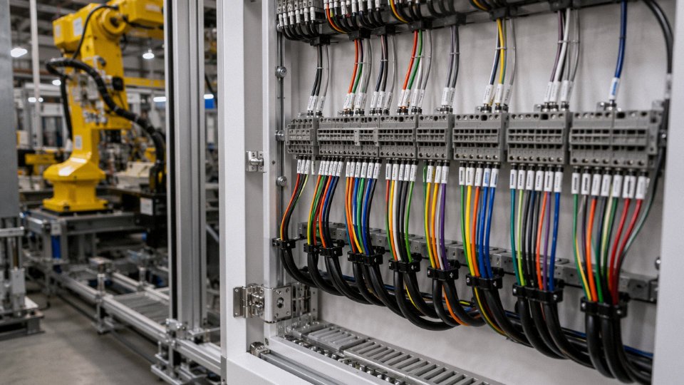
A vague specification is an open invitation for a supplier to substitute a cheaper product that technically meets the letter of an incomplete document. A properly written data sheet for a control cable specifies: conductor material and flexibility class (annealed copper, class 2 for fixed installation or class 5 for flexible service), cross-sectional area, number of cores, insulation material and color scheme or numbering system, screen type if required (individual pair foil, overall braid, both), armor if the route demands it, jacket material and outer color, voltage rating (300/500 V is typical for most 24 VDC and 120 VAC control circuits; 600/1000 V where the routing passes through higher-voltage zones), operating temperature range, and the test standards the finished cable must pass. Leave any of those fields blank and you will likely receive something that is close but not quite right.
Step 4 — Qualify the Supplier Against the Target Market
Product certification is not interchangeable across markets. CE marking covers the European Economic Area. UL listing is required for many North American industrial machinery applications. CCC is mandatory for products sold into the Chinese domestic market. SASO covers Saudi Arabia; INMETRO covers Brazil. A manufacturer that holds the right marks for your market has already been audited against the relevant construction and test standards — that is the shortcut that saves you running independent qualification tests on every drum.
Jinda Special Cable Group holds product certifications for multiple international markets and operates under an ISO 9001-certified quality system across all five of its production bases in China.True
This reflects publicly stated certifications and quality system registrations maintained by the manufacturer; ISO 9001 certification is independently audited on a recurring basis.
Step 5 — Require Traceability Documentation from Drum to Test Report
Every cable drum shipped to site should arrive with a factory test report that explicitly lists each core’s color or numeric sequence, measured conductor resistance per unit length, insulation resistance between cores, and high-voltage withstand result. That document is not a nice-to-have — it is the baseline your commissioning team uses during site acceptance testing and the record your maintenance team references five years later when a fault appears. Drums without it shift that verification burden entirely onto your site crew, usually at the worst possible moment.
Procurement engineers who work through this five-step sequence consistently report fewer site NCRs, faster commissioning, and cleaner handover documentation. The discipline is not complicated; it just requires resisting the pressure to skip ahead.
Shandong Jinda Special Cable Group has been manufacturing control and instrumentation cables since 1987, supplying projects across more than 50 countries from five production bases covering roughly 470,000 m² of manufacturing space. Whether your project requires IEC-compliant multi-core control cable in standard colors, NEC-compliant constructions with UL listing, IS-rated instrumentation cable, or a custom specification built around a non-standard color scheme, Jinda’s technical team can review your data sheet, confirm compliance with the governing standard, and provide a competitive quotation with full supporting documentation. Contact Jinda Special Cable Group to discuss your project requirements.