Specify the wrong cable on a purchase order and you may not discover the error until the equipment arrives on-site, the plug physically won’t fit the outlet, or — worse — it fits but the current rating is wrong and you’re looking at a tripped breaker, overheated insulation, or a scrapped production shift. That gap between “a power cable with three prongs” and its actual technical designation costs procurement teams real money: expedited re-orders, airfreight charges to fix a sea-freight mistake, and downtime that nobody budgeted for.
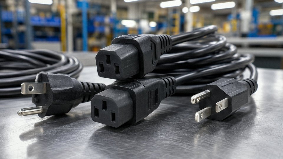
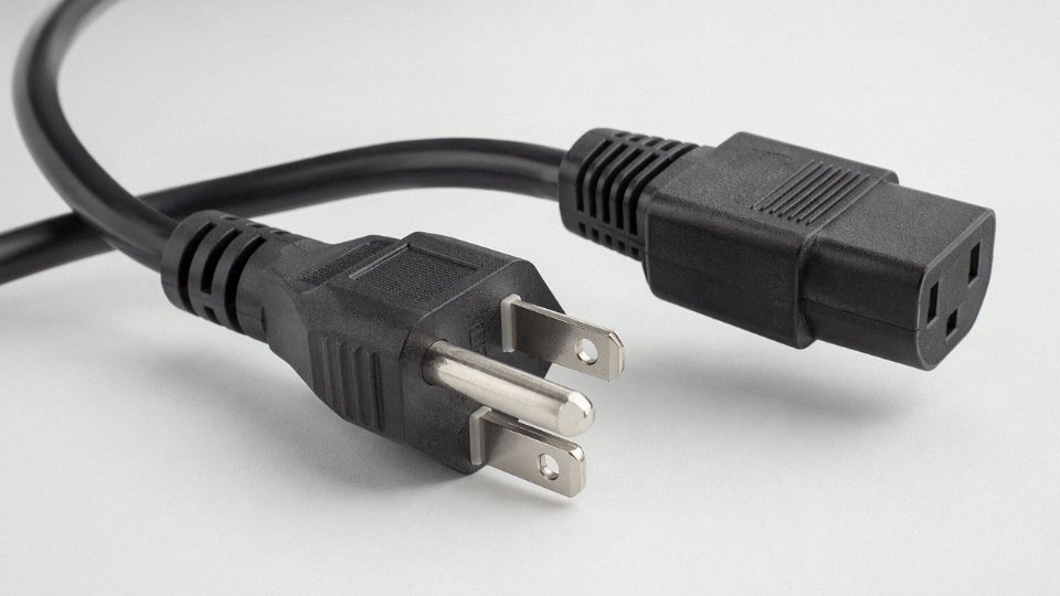
A three-prong power cable is most commonly called an “IEC 60320 C13 power cord” in international and data center applications, or a “NEMA 5-15 power cord” in North American contexts. The third prong is the grounding pin, and the full cable name always combines the connector standard, current rating, and voltage — because those three variables together determine whether the cable is safe and legal for your specific application.
What makes this surprisingly complicated is that the same physical cable sitting in a warehouse in Shanghai, Rotterdam, and Houston may carry three different part numbers, satisfy three different standards, and be legal in exactly one of those three markets. The naming conventions aren’t arbitrary — they encode real electrical and safety information — and understanding them properly changes how you spec, source, and inspect incoming stock.
The Third Prong Explained: Ground, Earth, and Protective Conductor Functions
Pull apart any standard grounded power cable and you’ll find three conductors, each doing a distinct job. Understanding what those jobs actually are — not just at a textbook level but in terms of what happens on a real circuit under fault conditions — is what separates competent cable specification from guessing.
Line, Neutral, and Protective Earth: What Each Conductor Actually Does
The Line conductor (called “Hot” in North American parlance) carries current from the supply to the load. Neutral carries it back, completing the circuit. These two are doing the functional work of power delivery. The third conductor — Protective Earth, or PE — carries nothing under normal operating conditions. Zero current, zero voltage drop. It just sits there, bonded between the equipment chassis and the building’s earthing system.
That changes the instant something goes wrong.
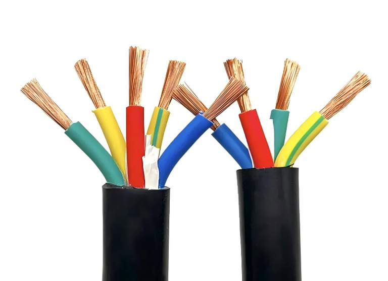
Color coding varies by region, and getting this wrong during field assembly is a genuine hazard. Under IEC 60446, the standard used across Europe, most of Asia, and many export markets: Line is brown, Neutral is blue, PE is green-yellow striped. Under NEC (North America): Line is black, Neutral is white, ground is green or bare copper. Some older UK installations used red/black/green before harmonization. If you’re sourcing cable for multi-region distribution, confirm which color scheme applies — a procurement manager who ships IEC-coded assemblies into a facility wired to NEC conventions is creating a labeling headache at minimum, and a live-neutral reversal risk at worst.
The Fault Current Path: Why the Third Prong Is a Safety Device, Not a Formality
Here’s the fault scenario that justifies the PE conductor’s existence. Suppose a live conductor inside a metal-chassis appliance chafes through its insulation and contacts the chassis. Without a PE connection, the chassis sits at line voltage — possibly 230V AC. A user who touches that chassis while standing on a grounded surface becomes the fault current path. Depending on body resistance and contact conditions, that’s potentially lethal.
With a proper PE connection, that same fault drives current down the low-impedance ground path to earth, creating a short-circuit condition that trips the breaker or blows the fuse — typically within milliseconds. The chassis voltage collapses before a human can be harmed.
The concepts of touch voltage (the voltage a person would experience across their body during a fault) and leakage current (the small, normally acceptable current that flows to earth through insulation and parasitic capacitance) are both shaped by how well the PE conductor is implemented. Leakage currents in the 0.5–3.5 mA range are typical for IT equipment; above roughly 5 mA, you’re approaching the threshold where RCDs/GFCIs trip, and above 10–30 mA you’re in physiologically dangerous territory.
Earthing System Topology Affects How the Third Prong Behaves
Not all earthing systems work the same way, and this matters for industrial installations and data center design. In a TN-S system, the PE and Neutral are kept fully separate from source to load — cleanest noise performance, preferred for sensitive electronics. TN-C-S (the PEN arrangement common in UK domestic supplies) combines them in the supply but splits them at the consumer unit. In a TT system, the equipment earth goes to a local ground electrode independent of the supply neutral, which means fault loop impedance is higher and RCD protection becomes more critical. IT systems, used in operating theaters and some offshore installations, float the supply entirely from earth — the third prong still matters for bonding but fault detection works differently.
The PE conductor carries no current under normal operating conditionsTrue
The protective earth conductor is only activated during a fault event; under normal operation it carries no load current, which is why its continuity is easy to overlook during maintenance until a fault exposes the omission.
Class II Equipment and the Legitimate Two-Prong Exception
Double-insulated Class II appliances — many handheld power tools, laptop chargers, some small kitchen appliances — achieve safety through reinforced insulation rather than through a chassis ground connection. They use two-prong plugs legitimately, and that’s not a shortcut; it’s a recognized design strategy codified under IEC 61140. The three-prong arrangement is specifically required for Class I equipment, where a single layer of insulation between live parts and the accessible metal chassis means the PE connection is the last line of defense.
The relevant standards to have on your desk: IEC 60364 for low-voltage electrical installations (the international framework), NEC Article 250 for grounding and bonding in North American facilities, and BS 7671 (the IET Wiring Regulations) for UK and many Commonwealth-influenced markets. These aren’t interchangeable documents. A cable assembly that satisfies one may require additional testing or construction changes to satisfy another.
IEC 60320 Connector Types: C13, C15, C19, and Their Matching Plugs
The IEC 60320 standard is the backbone of detachable power cord design globally. If you’ve ever plugged a computer into a wall, connected a server to a PDU, or watched a hotel kettle boil, you’ve used this system without thinking about it. Understanding how it’s structured matters the moment you’re specifying cables for a mixed equipment room, sourcing replacements during a line stoppage, or auditing a facility for thermal compliance.
How the Standard Is Organized
IEC 60320 defines couplers — meaning the cable-end connector that plugs into equipment — and appliance inlets — the socket built into the device itself. They are always named in pairs: the coupler takes the odd number, the inlet takes the even. C13 mates with C14. C15 with C16. C19 with C20. C21 with C22. This pairing logic is deliberate and worth memorizing, because physically, some connectors look deceptively similar. A C13 will not seat correctly in a C16 inlet due to a notch difference — the asymmetry is intentional, a physical interlock to prevent connecting a 70°C-rated connector to a high-temperature application.
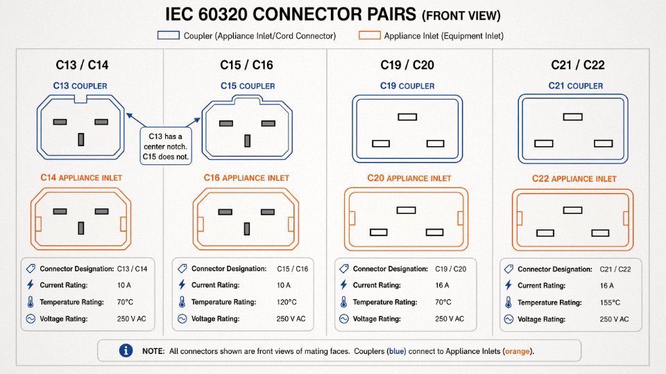
Connector Comparison: Ratings and Real Applications
| Connector Pair | Current Rating | Temperature Rating | Voltage | Typical Application |
|---|---|---|---|---|
| C13 / C14 | 10 A | 70 °C | 250 V AC | Desktop PCs, monitors, printers, AV equipment |
| C15 / C16 | 10 A | 120 °C | 250 V AC | Electric kettles, small appliances with heating elements |
| C19 / C20 | 16 A | 70 °C | 250 V AC | Rack PDUs, UPS units, server chassis |
| C21 / C22 | 16 A | 155 °C | 250 V AC | High-temperature industrial equipment, certain lab instruments |
The C13/C14 pair handles probably 80% of what you’ll encounter in a typical office or light-industrial setting. Nearly every desktop power supply worldwide uses a C14 inlet — it’s been essentially standardized since the mid-1980s. The C19/C20 pair steps up to 16 A and is the default for 1U and 2U servers, rack-mount UPS systems, and PDUs in data centers. Mix these up — cable marked for C13 feeding into a C20 inlet via an adapter — and you’re running 16 A through a 10 A connector. That’s not a theoretical concern; it’s a real fire risk, and it happens in hastily assembled server rooms more than anyone publicly admits.
The Temperature Rating Problem Nobody Talks About
The C15/C16 and C21/C22 pairs exist specifically because plastic housings and internal contacts behave differently under sustained heat. A kettle, for example, generates enough ambient heat around its inlet that a standard 70°C-rated C13 connector will soften, deform, and eventually arc. The C15’s notch modification physically prevents someone from using a C13 cord on a C16 kettle inlet — in theory. In practice, worn inlets and off-spec connectors occasionally allow improper mating. If you’re sourcing cables for appliances with heating elements, the temperature rating on the connector label is not decorative.
C13 and C15 connectors are interchangeable in most applicationsFalse
While both are rated 10 A / 250 V AC, C13 is rated to 70°C and C15 to 120°C. Their housings are physically notched differently to prevent cross-mating. Using a C13 on a high-temperature appliance inlet risks thermal deformation and potential arcing.
Locking Connectors in Data Center Environments
Standard C13/C14 and C19/C20 connections rely entirely on friction retention. In a dense rack where cables are routinely jostled during maintenance — someone reaching past a bundle to swap a drive, a cable management arm catching a cord — accidental disconnection is a real operational risk. Locking C13 and C19 variants address this with integrated retention clips or twist-lock collars. Some facilities standardize on these across the entire rack build; others use simple clip-on cord locks as a cheaper retrofit. Either approach is workable. The mistake is ignoring the problem entirely until an unexpected server drop causes a longer postmortem than the original task.
Custom Assembly Considerations
Not all IEC 60320 applications are off-the-shelf. Cable cross-section, outer jacket material, and cord length all get specified in real procurement. A 1.5 mm² conductor handles the C13’s 10 A rating with margin; for C19/C20 at 16 A in a hot aisle, 2.5 mm² is common practice, depending on ambient temperature and run length. Jacket materials vary from standard PVC for general use to LSZH (low-smoke zero-halogen) for data centers and transit applications, and occasionally TPE or silicone-jacketed variants for elevated-temperature environments.
Jinda manufactures IEC 60320 cord sets across the full connector family, with configurable cable cross-sections from 0.75 mm² to 2.5 mm², lengths typically from 1 m to 5 m (custom lengths on order), and jacket options including PVC, LSZH, and rubber compounds. For bulk procurement or OEM supply, the connector pair, temperature rating, conductor cross-section, and jacket type all need to be specified explicitly — “a C13 cable” alone is not a complete specification.
Regional Plug Standards That Use Three Prongs: NEMA, BS 1363, CEE 7/7, AS/NZS 3112, and More
No single three-prong plug standard dominates globally. What works in a Chicago server room will not fit a socket in Munich, Sydney, or Mumbai — and specifying the wrong cord set for a destination market means either a useless shipment or a dangerous field modification. Here is a working reference for the main standards you will actually encounter.
NEMA 5-15P: North America’s Workhorse
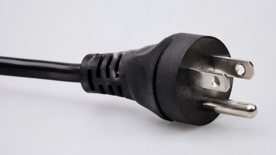
The NEMA 5-15P is rated 15A at 125V and is almost certainly the most manufactured three-prong plug on earth — roughly 4 billion compatible outlets exist across the US and Canada alone. Its geometry is simple: two flat parallel blades (line and neutral, with neutral slightly wider to enforce polarity) plus a round ground pin positioned below them. That round pin engages the socket first on insertion, which is intentional. The blade dimensions are tightly controlled under NEMA WD-6, and any deviation — even a few tenths of a millimeter on blade thickness — will cause rejection failures during UL inspection or create loose fit over time.
NEMA 5-20P and NEMA 6-15P: When 15A Is Not Enough
The NEMA 5-20P looks nearly identical to a 5-15P but the neutral blade is rotated 90°, forming a T-shape. This lets it plug into both 5-20R receptacles (20A rated) and standard 5-15R outlets. Used heavily in commercial kitchens, medical equipment, and dense office fit-outs. The NEMA 6-15P steps up to 250V at 15A — same round ground pin, but both flat blades are horizontal and identical in width. You see this on welding equipment, larger air compressors, and certain industrial test gear. Mixing these up during procurement is a genuine field problem; the voltage difference between a 5-series and 6-series cord is not something a user will notice until something fails.
BS 1363: The UK’s Deliberately Over-Engineered Plug
BS 1363 is the standard for the UK, Ireland, and much of Southeast Asia including Malaysia, Singapore, and Hong Kong. The plug carries three large rectangular blades in a triangular arrangement and — unusually — contains a mandatory fuse inside the plug body, typically 3A or 13A depending on the appliance. Sockets have spring-loaded shutters that only open when the longer earth pin (which is also the first to engage) pushes them aside. It is bulky and widely mocked, but the fuse and shutter combination gives it a genuine safety argument in residential environments. For export cord sets destined for these markets, the fuse rating must match the appliance’s actual current draw, not just the maximum plug rating.
CEE 7/4 Schuko vs. CEE 7/5 French: A Common Confusion
Schuko (CEE 7/4) is widely described as a “grounded European plug,” but it does not have a ground prong. The earth connection is made through two metal clips on the sides of the plug that contact recessed rails inside the socket. Two round pins carry line and neutral. This matters because a Schuko plug has no polarity — it inserts either way — and the earth contact engages by friction, not by a dedicated pin geometry. The French standard (CEE 7/5) solves this differently: the socket has a protruding round earth pin that inserts into a hole in the plug. CEE 7/7 is a hybrid plug body that works in both socket types, which is why most continental European power cords use it.
CEE 7/4 Schuko plugs do not have a ground prong — the earth connection is made through side contact clips, not a pin.True
The Schuko standard (CEE 7/4) uses lateral earth contacts on the plug body that mate with recessed metal rails in the socket. The plug has only two round current-carrying pins. This is consistent with IEC and DIN VDE documentation for the standard.
AS/NZS 3112: Australia and New Zealand’s Angled Flat Blades
AS/NZS 3112 uses three flat blades arranged in a V-shape — two angled flat blades for line and neutral, plus a vertical flat earth blade at the top. Since 2005, the standard has required insulated sleeves on the live and neutral pins, covering roughly the lower half of each blade. This reduces the risk of contact during partial withdrawal. The sockets are recessed, which adds mechanical protection. Supply voltage is 230V at 50Hz, so this cord set is not interchangeable with North American equipment without voltage verification.
BIS IS 1293 (India) and NBR 14136 (Brazil)
India’s IS 1293 standard uses three round pins — two current-carrying and one earth — in a triangular pattern. Pin diameter is 6mm for the standard domestic variant. It remains widespread across one of the fastest-growing manufacturing and consumer electronics markets globally, and international exporters who ignore it tend to find out about it the hard way when a container clears customs but the products cannot be plugged in. Brazil’s NBR 14136 (the IEC 60083-derived standard adopted around 2011) uses two round current-carrying pins plus a round earth pin, and has progressively replaced the older Brazilian NEMA-variant outlets, though legacy sockets still exist in older facilities.
Regional Standards Reference Table
| Standard | Primary Region | Voltage / Frequency | Current Rating | Ground Type |
|---|---|---|---|---|
| NEMA 5-15P | USA, Canada | 125V / 60Hz | 15A | Round pin |
| NEMA 5-20P | USA, Canada | 125V / 60Hz | 20A | Round pin |
| NEMA 6-15P | USA, Canada | 250V / 60Hz | 15A | Round pin |
| BS 1363 | UK, Ireland, Malaysia, Singapore, HK | 230V / 50Hz | 13A (fused) | Rectangular pin |
| CEE 7/4 Schuko | Germany, most of Europe | 230V / 50Hz | 16A | Side clips (no pin) |
| CEE 7/5 | France, Belgium, Poland | 230V / 50Hz | 16A | Socket-side pin |
| AS/NZS 3112 | Australia, New Zealand | 230V / 50Hz | 10A / 15A | Flat blade pin |
| IS 1293 | India | 230V / 50Hz | 6A / 16A | Round pin |
| NBR 14136 | Brazil | 127V or 220V / 60Hz | 10A / 20A | Round pin |
How Cord Set Sourcing Works in Practice
For bulk procurement across multiple destination markets, the practical approach is a standardized IEC cable assembly with a country-specific plug molded or mechanically assembled at one end. The cable itself — conductor cross-section, insulation rating, jacket material — can often be common across markets; what changes is the terminating plug and the certification mark it carries (UL for North America, BSI Kitemark for the UK, SAA for Australia, BIS for India, and so on). Jinda produces these as configurable cord sets, where the IEC or regional plug is specified per order and assembled to the same base cable construction, reducing inventory complexity for customers managing multi-market distribution. Lead times and minimum quantities vary by plug type and certification requirement, so early engagement on destination-market specifications avoids delays.
Cable Construction Inside a 3-Prong Power Cord: Conductors, Insulation, and Jacket Specifications
The connectors get most of the attention in specs and purchasing conversations, but the cable body itself is where most field failures actually originate — overheating at undersized conductors, jacket cracking in cold storage environments, insulation breakdown from exposure to cutting fluids. Getting the construction right matters as much as getting the plug standard right.
Conductor Material and Stranding
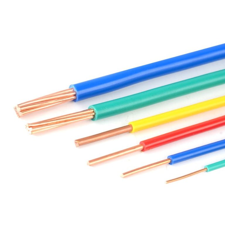
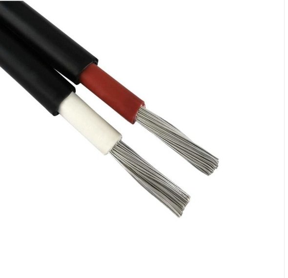
Virtually all flexible power cords use annealed copper, and for good reason. Aluminum has roughly 61% of copper’s conductivity by cross-section, which means you need a larger aluminum conductor to carry the same current — a real problem when you’re routing cables through conduit or trying to terminate into a standard IEC connector. Aluminum also work-hardens under repeated flexing, which makes it genuinely unsuitable for portable or frequently moved cords.
The stranding class matters more than most buyers realize. IEC 60228 Class 5 and Class 6 define fine-stranded conductors — Class 6 being the finer of the two, used where the cord flexes constantly, like a drag-chain application or a hand-held power tool. A stiff Class 2 solid or coarse-stranded conductor might pass a continuity test on the bench but will develop micro-fractures in the copper within months on a machine that vibrates or cycles repeatedly.
Cross-Sectional Area and Ampacity
The sizing relationship is straightforward in principle, messy in practice because ambient temperature, bundling, and run length all shift the real-world safe current.
| Cross-section | Approx. AWG equivalent | Typical safe current (open air, 40°C) | Common application |
|---|---|---|---|
| 0.75 mm² | 18 AWG | Up to ~6 A | Light-duty appliances, lamps, chargers |
| 1.0 mm² | 17–18 AWG | Up to ~10 A | Desktop equipment, IEC C13 cords |
| 1.5 mm² | 16 AWG | Up to ~16 A | Power strips, small appliances, C15 cords |
| 2.5 mm² | 12–13 AWG | Up to ~25 A | Industrial equipment, C19 cords, machinery |
The ampacity figures above assume a single cord in free air. Bunch six cords together in a cable tray and those numbers drop — typically by a derating factor that depends on how tightly they’re packed and whether ventilation exists.
Insulation Materials
PVC is the default: cheap, widely available, rated to 70°C, and adequate for most office and light-industrial use. The problem appears at temperature extremes. PVC gets brittle below about -15°C and softens and oozes plasticizer when run continuously near its upper limit, especially in confined spaces.
XLPE (cross-linked polyethylene) handles continuous 90°C service and resists a broader range of chemicals — useful around hydraulic fluids or cleaning agents. Rubber, including neoprene compounds, stays flexible at low temperatures and tolerates outdoor UV exposure reasonably well, which is why you see it on construction-site extension cords. Silicone insulation pushes continuous ratings to 150–180°C; it’s expensive and the outer surface picks up contamination easily, but in oven equipment or near heat-sealing machinery there’s often no practical alternative.
Jacket Types and the H-Code System
European harmonized cables carry an H designation that encodes the construction in the cable marking itself. H05VV-F, for example, breaks down as: H = harmonized, 05 = 300/500V rated, V = PVC insulation, V = PVC outer sheath, F = fine-stranded flexible conductor. H07RN-F substitutes 07 (450/750V), R for rubber insulation, and N for a neoprene outer jacket — that’s your heavy-duty outdoor or workshop cord.
PUR (polyurethane) jackets are worth specifying when the cord will sit in oil mist or run through a drag chain. PVC jackets crack and harden in those conditions within a year or two; PUR resists both hydrocarbon contamination and the constant flexing cycle. The cost premium is real — PUR compounds run roughly 20–40% more than standard PVC jacket material, depending on formulation and order volume — but a cord that lasts five years instead of eighteen months pays for itself quickly in a production environment.
For halogen-free flame-retardant requirements — data centers, public buildings, tunnels — TPE jacket compounds meeting IEC 60332 are the standard choice. They don’t emit toxic halogen gases during a fire, which is why many European building codes and data center specs now mandate them.
Shielding
Standard three-conductor power cords are unshielded. That’s fine for most applications. Where it becomes a problem is in medical equipment, sensitive measurement instruments, or equipment running near variable-frequency drives — environments where conducted interference on the power cable can corrupt signals or violate EMI standards like IEC 61000. A foil or braid shield over the three-core assembly, with the shield terminated to ground at one end, reduces this coupling substantially.
Standard unshielded 3-prong power cords are suitable for most industrial and commercial applications without causing EMI issuesTrue
EMI problems from unshielded power cords typically only occur in sensitive environments such as medical equipment, precision instrumentation, or near variable-frequency drives. For general-purpose use, unshielded construction is standard and adequate per IEC 60320 and related standards.
Jinda’s Production Specifications
Jinda manufactures across this full construction range — 0.75 mm² through 2.5 mm² and beyond, PVC, PUR, TPE, and rubber jacket options, unshielded and shielded configurations. Jacket colors can be customized, and cable surface printing of rated voltage, current, approvals, and customer part numbers is available for large orders. Approval options include UL (North America), CE (Europe), SAA (Australia/New Zealand), and BSI (UK), allowing a single manufacturing source to supply cords for multiple destination markets — which simplifies procurement considerably when you’re managing regional variants of the same product line.
Safety Certifications Required for 3-Prong Power Cables Sold in Major Markets
Sourcing a three-prong power cable that “looks compliant” is not the same as sourcing one that actually is. Procurement teams get burned on this regularly — a shipment clears customs, reaches the OEM customer, and then fails a factory audit because the UL mark on the molded plug is a sticker rather than a legitimate listing. Understanding what each certification actually requires, and how to verify it independently, is worth more than any supplier’s compliance checklist.
North America: UL and CSA Requirements
For the US market, the two primary standards governing cord sets are UL 62 (covering the flexible cord itself) and UL 817 (covering the assembled cord set or power-supply cord). The distinction matters operationally: a cord can carry UL 62 recognition for its wire construction while the finished assembly still needs UL 817 listing to be sold as a complete cord set. This is the UL Recognized vs. UL Listed split that trips up a lot of buyers. UL Recognized (the backwards-UR symbol) applies to components intended for use inside an end product — not for standalone sale. UL Listed (the conventional UL mark) applies to complete, saleable assemblies. Sell a Recognized-only cord set into retail or as a field-replaceable part in North America and you have a compliance gap, full stop.
Canada runs parallel requirements under CSA C22.2 No. 49. Many suppliers hold a combined cULus mark covering both jurisdictions, which simplifies procurement considerably. Verify any claimed UL file number directly at UL’s public database (iq.ul.com) — search by file number, not by product name. A legitimate listing shows the exact product category, the manufacturing location, and the applicable standards. If a supplier’s “UL certificate” PDF doesn’t correspond to an active file in that database, treat it as suspect.
Europe and the UK
CE marking under the Low Voltage Directive 2014/35/EU is a legal requirement for power cables placed on the EU market — not optional, not a quality signal, just the floor. The HAR mark (a hexagonal symbol with the country code letters) is separate and often misunderstood. HAR is a voluntary harmonization mark administered by CENELEC national members; it signals that the cable was produced and tested to harmonized European cable standards (like HD 21 or HD 22 series) and that production is regularly audited. In practice, major European industrial buyers and retailers routinely demand HAR as a procurement condition even though it’s technically voluntary, because it provides third-party manufacturing surveillance that CE self-declaration doesn’t.
Post-Brexit, the UKCA mark is now required for products placed on the Great Britain market (England, Scotland, Wales). Northern Ireland sits under a separate regime. For BS 1363 plugs specifically, BSI certification under BS 1363-1 is effectively mandatory — the standard requires that plugs be approved by a recognized test house, and BSI is the dominant body for this. Substituting a CE-only plug into a UK-bound cord set is a compliance failure, not a technicality.
Asia-Pacific and Emerging Markets
Australia and New Zealand require the RCM mark (Regulatory Compliance Mark), which consolidated the older C-tick and A-tick schemes. Cord sets destined for these markets need to satisfy AS/NZS 3191 (cord sets) and AS/NZS 3112 (plugs and socket-outlets), with certification through an accredited body — commonly called SAA approval in trade shorthand, after the Standards Association of Australia.
China’s CCC certification (China Compulsory Certification, sometimes written 3C) applies to cord sets under GB 17465 and related standards. For a manufacturer like Jinda, domestic CCC compliance is the operational baseline — and it also builds the internal testing and documentation infrastructure that supports re-export certification work, since many of the conductor and insulation test protocols overlap with IEC baselines.
India’s BIS certification under IS 1293 deserves attention right now. India has been tightening import enforcement on electrical goods, and buyers who assumed informal tolerance of non-BIS product are finding customs holds and consignment rejections increasingly common. If India is on your distribution map, treat BIS as mandatory, not aspirational.
A UL Recognized mark on a cord set component satisfies UL listing requirements for the complete assembled cord set sold as a standalone product in North America.False
UL Recognized (cUR/UR) applies to components intended for incorporation into end products. A complete cord set sold as a standalone product in North America requires UL Listed status under UL 817, not merely UL Recognized status for its sub-components.
Reading Supplier Certification Documents
When reviewing a supplier’s test report, check three things: the issuing lab’s accreditation (ILAC-MRA membership is the baseline for international recognition), whether the tested product description actually matches what you’re buying (conductor cross-section, jacket material, connector type), and the report date relative to any standard revision cycles. A test report from 2017 may not cover a 2019 standard amendment.
Jinda holds active certifications including UL listing, CE with HAR mark, RCM, and BSI approval for BS 1363 cord sets, maintained through an in-house laboratory that handles routine production testing and supports the documentation trails third-party auditors expect to see. That internal capability — calibrated equipment, retained samples, traceable test records — is what separates a supplier whose certifications survive a factory audit from one whose paperwork looks fine until someone actually visits the plant.
How to Select the Right 3-Prong Power Cable for Industrial, Commercial, and Data Center Applications
Misspecifying a power cord is one of those mistakes that looks minor on paper until it causes a tripped breaker mid-shift, a melted connector on a PDU, or a customs hold at the destination port because the certification mark is wrong for that country. Getting the specification right requires matching four things simultaneously: the application’s load and duty cycle, the installation environment, the regional regulatory requirements, and the connector interface at both ends.
Matching Cable Spec to Application Segment
Light-duty office and IT equipment — desktop PCs, monitors, small network switches — almost universally uses C13-terminated cords, rated at 10A, built on H05VV-F flexible cable (typically 3×0.75 mm² or 3×1.0 mm²). These are fine for their intended load. Put one on a laser printer that pulls 12–15A on startup and you’re already outside the cord’s design envelope.
Heavy commercial loads (rack-mount servers pulling continuous 16A, commercial catering equipment, AV amplifier racks) need C19/NEMA L6-20 connectors and H07RN-F rubber-jacketed cable, usually 3×1.5 mm² to 3×2.5 mm². The rubber jacket matters in environments with trolleys, cleaning chemicals, or temperature swings — PVC cords get brittle and crack in cold warehouses, and H05VV-F simply isn’t rated for rough handling.
Industrial machine tools are a different conversation entirely. CNC machining centers, welding power supplies, and large compressors typically run on NEMA 6-30, NEMA 6-50, or IEC 60309 plugs at 30–50A. Here the jacket must be rubber or thermoplastic elastomer (TPE), the conductors are 3×4 mm² to 3×10 mm² depending on load, and molded strain relief is not optional — it’s mandatory. A loose cord connection on a 40A circuit that cycles on and off twenty times a day will fail within months.
Data center PDU tails sit in their own category: custom lengths (often 0.5 m to 3 m, cut to rack geometry), C13 or C19 locking connectors to prevent accidental disconnection, and tight length tolerances because cable management in a dense rack isn’t forgiving. Locking C13/C14 connectors (compatible with standard IEC 60320 C14 inlets) are worth the small premium in any rack environment where vibration or cable weight could cause intermittent disconnects.
Temperature Derating — Don’t Ignore It
A cable’s ampacity rating assumes a 30°C ambient. Raise the ambient — inside a cabinet, near a furnace, in a data center hot aisle — and you must derate. The table below gives working multipliers based on IEC 60364 guidance:
| Ambient Temperature | Derating Factor | Practical Effect on a 16A-Rated Cord |
|---|---|---|
| 30°C (baseline) | 1.00 | 16A usable |
| 40°C | 0.87 | ~14A usable |
| 50°C | 0.71 | ~11A usable |
| 60°C | 0.50 | ~8A usable |
A data center hot aisle running at 45°C ambient is not unusual. At that temperature a nominally 16A cord should only carry around 12–13A continuously. This matters when you’re loading PDUs close to nameplate.
Cable Length and Voltage Drop
Keep voltage drop below 3% for sensitive electronics; some equipment specs tighten that to 2%. The table below covers the most common load currents for 120V and 230V systems, using copper conductors:
| Load Current | Max Cord Length (120V, <3% drop) | Max Cord Length (230V, <3% drop) |
|---|---|---|
| 10A | ~9–11 m (depends on conductor cross-section) | ~18–22 m |
| 16A | ~6–8 m | ~12–15 m |
| 20A | ~4–6 m | ~9–12 m |
These ranges shift with conductor size — a 2.5 mm² cord at 16A buys you significantly more length than a 1.5 mm² cord at the same current.
Installation Method Matters More Than People Assume
A free-air cord in open space carries its rated current without much concern. The same cord lying in a bundled cable tray with seven other cords needs another derating step — typically 0.6–0.75× depending on bundle count, per IEC 60364-5-52. In practice, cable tray runs in server rooms are often packed tighter than design intent because someone added equipment without updating the cable schedule. That’s how you end up with warm cords that nobody investigates until something trips.
Conduit installation is worse for heat dissipation than free air, and rigid conduit limits your flex jacket choices — you need to specify a jacket material that pulls smoothly and doesn’t compress under conduit fittings.
Bundled power cords in dense cable trays can require ampacity derating of 25–40% compared to free-air rated valuesTrue
IEC 60364-5-52 and NEC Table 310.15(B)(3)(a) both require grouping/bundling derating factors. For 7–9 bundled conductors, typical derating factors fall in the 0.6–0.7 range, which corresponds to a 30–40% reduction in usable ampacity.
Strain Relief and Connector Retention
Standard push-fit IEC connectors rely entirely on friction. That’s adequate for a desktop PC that never moves. For a machine tool that vibrates at 50–100 Hz, or a portable generator that gets dragged across a yard, friction retention will eventually work loose. Specify molded overmold boots on the connector, metal cable glands where the cord enters the equipment, and locking connector variants for any PDU or rack application. The cost difference between a standard C19 connector and a locking C19 is negligible against the cost of an unplanned reboot in a live production environment.
Procurement Specification Checklist
A purchase order that just says “16A power cord” will get you something, but probably not what you need. At minimum, a proper spec includes:
- Conductor cross-section (mm² or AWG) and number of cores
- Jacket material (PVC, rubber/H07RN-F, TPE, silicone — specify operating temperature range)
- Plug type and standard (NEMA 5-15, IEC 60309 3P+E, BS 1363, etc.)
- Socket/connector type (C13, C19, locking variant, flying lead)
- Overall finished length with tolerance (±50 mm is typical for industrial)
- Required certifications for the destination market (UL, CSA, VDE, SAA, CCC, etc.)
- Quantity and delivery timeline (this affects whether tooled molded ends are economic)
Custom OEM Cord Sets Through Jinda
For custom assemblies — specific lengths, non-standard plug combinations, branded overmolds, or mixed regional variants in a single purchase order — Jinda’s OEM cord set program covers sample approval typically within 10–15 working days from confirmed specification, with production lead times of 4–8 weeks depending on order volume and tooling requirements. Minimum order quantities for custom molded configurations usually start around 500–1,000 pieces per SKU, though this varies with cord complexity and connector tooling investment. Standard off-the-shelf configurations carry no MOQ restriction for international orders. Sample sets can be dispatched for third-party lab testing before bulk production is confirmed — which any serious procurement process should include.
Common Failures, Misuse Scenarios, and Field Troubleshooting for 3-Prong Power Cords
Power cords fail more often than people expect — and usually in the least convenient way. Most failures are slow, not sudden. A cord that’s been flexed hundreds of times at the strain relief, dragged across a cable tray edge, or left coiled under a workbench heater doesn’t announce its degradation until something trips, sparks, or stops working entirely.
Conductor Fracture at Strain Relief Points
The strain relief is the most mechanically stressed point on any power cord. In equipment that moves — CNC machines, rolling test carts, portable tools — the cord bends at the same spot thousands of times. What eventually breaks isn’t the middle of the conductor; it’s the strands immediately behind the molded boot, where the cable transitions from rigid to flexible. You’ll often see intermittent power loss that disappears when you hold the cord at a certain angle. That’s a near-fracture conductor. Don’t tape it and move on. The fix is replacement.
Abrasion from cable tray edges or through sharp conduit knockouts is the other common path to failure. PVC jackets, especially the thinner grades used on light-duty cords, will wear through in six to eighteen months in a busy tray depending on how much the cables move against each other and whether the tray edges were deburred properly — which in my experience they often weren’t.
Ground Pin Failure: The Fault That Hides
A broken ground conductor is dangerous precisely because equipment often keeps running normally. The live and neutral carry current; the ground just sits there waiting. Until it’s needed.
Detection is straightforward. A plug-in outlet tester — the kind with three indicator LEDs, available from any electrical supplier for a few dollars — will flag an open ground immediately. For equipment already installed, a multimeter set to continuity mode between the ground pin of the detached plug and the equipment chassis will confirm whether the protective path is intact. Resistance should be under roughly 0.5 Ω; anything higher warrants investigation.
A broken ground conductor in a power cord causes immediate equipment shutdown.False
Equipment typically continues operating with a broken ground because live and neutral conductors still carry current. The broken ground only becomes apparent during a fault condition, making it a hidden and therefore more dangerous failure mode.
One underappreciated symptom: nuisance RCD or GFCI tripping without an obvious cause. If the ground conductor is intermittently making contact with the neutral internally — a failure pattern that happens when insulation abrades inside a molded plug — the imbalance triggers the RCD even though nothing else seems wrong. Don’t just reset it and assume a transient.
Overloading Signs and the Correct Response
A warm cord along its entire length, a plug body that’s discolored or slightly deformed, a faint smell that’s not quite burning but not neutral either — these are not minor annoyances. They indicate the cable is running near or above its rated ampacity. Repeated breaker trips without an obvious fault confirm it. Pull the cord, check the nameplate amperage of the load against the cable rating, and size up appropriately. Don’t add a higher-rated breaker to compensate.
Wrong Connector Substitution
Using a C13 cord on a 120°C-rated appliance — an electric kettle, a catering urn, some older laser printers — is a genuine fire risk. The C13 connector is rated for 70°C maximum. The C15 looks almost identical but has a notch on the female connector specifically to prevent this swap; some lower-quality equipment omits that detail in the socket, which makes the mismatch physically possible. Check the temperature rating on the equipment’s IEC inlet, not just whether the plug fits.
Daisy-chaining power strips in data center racks is a variation of the same problem. Each strip adds impedance and thermal load. In a fully populated rack drawing 4–6 kW, a chain of two consumer-grade strips can put the conductors in the last strip well above their rated current. This is a code violation in most jurisdictions and a fairly common cause of rack-level outages.
Environmental Damage Patterns
UV exposure degrades standard PVC jackets within one to two seasons in outdoor installations, depending on UV index and whether the jacket compound includes stabilizers. The jacket becomes brittle and cracks along its length — often not visibly alarming until it flakes. PUR-jacketed cables resist UV better and handle oil absorption without swelling; neoprene is tougher mechanically but can crack in sustained low-temperature environments below around -20°C.
Rodent damage in industrial facilities follows a predictable pattern: gnawed sections near walls and under equipment bases, usually where cables rest on the floor. The damage often cuts through jacket and insulation in the same bite, creating an immediate fault rather than a gradual one.
Repair vs. Replace — No Ambiguity Here
IEC 60884 and UL 817 are explicit: molded plugs cannot be field-repaired. The molded overmold is part of the safety construction. If the plug body is cracked, a pin is loose, or the cable has pulled back into the housing, replacement is the only compliant option. Serviceable plugs — the type with a removable cover and screw terminals — can be replaced in the field by a qualified electrician, but only if the cable itself is undamaged from that point back to the equipment.
Quarterly visual inspections are a reasonable baseline for light commercial use. Monthly inspection makes sense in industrial environments with heavy flex cycles, oil exposure, or forklift traffic nearby. After any extreme event — flood, fire, physical impact from a dropped load — inspect before re-energizing, regardless of when the last scheduled inspection was.
Frequently Asked Questions About 3-Prong Power Cables
What is the official name of the 3-prong cord used with computers?
The correct term is an IEC 60320 C13 power cord, or more precisely, a C13-to-[plug type] cord set — where the plug type depends on the destination country. A cord going to North America would be called a C13-to-NEMA 5-15P cord set; the same cord bound for the UK becomes a C13-to-BS 1363 cord set. Both connectors matter in the name. Saying just “kettle lead” or “PC power cable” works on the shop floor but creates ambiguity the moment you’re sourcing from overseas or writing a procurement specification. The IEC designation is what gets you the right part.
Is it safe to use a 3-prong to 2-prong adapter (cheater plug)?
Technically, the adapter itself isn’t automatically dangerous — the problem is how it’s used. That little green screw tab on the adapter is supposed to connect to a grounded outlet cover plate screw, which then completes the ground path. In practice, almost nobody does this, and even when they do, older outlets in buildings from the 1960s or earlier often have an ungrounded box behind the plate anyway. So the ground path is simply gone.
On Class I equipment — motors, metal-chassis instruments, most industrial gear — that missing ground means a fault current has nowhere safe to go except through whoever touches the enclosure. Many jurisdictions, including those following NEC guidelines in the US and IEE Wiring Regulations in the UK, prohibit permanent installation of cheater plugs. For a temporary bench test in a controlled setting, maybe. As a long-term fix in a production environment, don’t.
A 3-prong to 2-prong adapter fully restores ground protection when installed.False
The adapter only restores the ground path if the small bonding tab is physically connected to a verified grounded outlet cover screw — a step that is almost universally skipped in practice, leaving the equipment chassis ungrounded.
What does the round prong do?
It’s the protective earth (PE) conductor. Its job is to provide a low-impedance path back to the electrical panel so that if a live conductor contacts the equipment chassis, fault current flows through the wire rather than through a person. The idea is simple: make the unintended path so easy for electricity to follow that the breaker trips before anyone gets hurt. Without it, a double-fault on a metal-framed machine can energize the entire chassis at line voltage with no indication whatsoever.
Can I replace a 3-prong cord with a 2-prong cord?
Only on Class II double-insulated equipment where the original manufacturer explicitly documents that it’s permissible — think most handheld power tools and some consumer electronics. On Class I equipment, swapping in a 2-prong cord removes the protective earth connection, creates a safety code violation, and voids any existing safety certification. It’s not a grey area.
Why do some countries use flat prongs and others use round pins?
Each country developed its own plugs and sockets before any serious international harmonization effort existed. The US settled on flat parallel blades (NEMA) in the early 20th century; much of continental Europe adopted round pins (CEE 7 family); the UK went its own direction entirely with the large rectangular-blade BS 1363 system, partly to incorporate fusing at the plug. IEC 60320 came later and solved a narrower problem — it standardized the appliance-side detachable connector (the C13, C15, C19, and so on) without trying to replace national wall outlet standards. That’s why a single C13 cord with the right country-specific plug on the other end can power the same laptop in Tokyo, Frankfurt, or São Paulo.
What gauge wire should a 15-amp extension cord use?
For runs up to roughly 25 ft (7.6 m), 14 AWG (2.5 mm²) handles 15A with acceptable voltage drop under most circumstances. Stretch that to 50 ft (15 m) or feed equipment with tight voltage tolerances — CNC drives, variable-frequency drives, precision test equipment — and you want 12 AWG (4 mm²). Cord gauge matters more than people give it credit for; undersized conductors on long runs waste energy as heat and can cause nuisance tripping or equipment undervoltage faults, especially if several cords are daisy-chained in a temporary setup.
How do I know if my power cord is UL listed?
Look for the UL mark molded into the plug body and printed on the cable jacket, then go one step further: verify the supplier’s UL file number at ul.com/database. A mark on the cord means nothing if the file number doesn’t resolve to an active listing that actually covers that product category. Counterfeit marks exist; the database check is the only reliable confirmation. If a supplier can’t provide a UL file number, treat the listing claim as unverified.
What is the difference between H05VV-F and H07RN-F cable?
H05VV-F is a light, flexible PVC-insulated cord rated 300/500V, designed for indoor use with stationary or semi-stationary appliances — office equipment, domestic appliances, light commercial gear. H07RN-F is a heavy-duty rubber-jacketed cord rated 450/750V, built for outdoor environments, construction sites, and industrial equipment where the cable sees mechanical abuse, moisture, oils, or wide temperature swings. Using H05VV-F in an outdoor or industrial role because it was cheaper or already in stock is a common and expensive mistake — the jacket degrades, the insulation cracks, and you end up with a failure that’s worse than the savings justified.
Sourcing 3-Prong Power Cables at Scale: How Jinda Supports Global OEM and Project Procurement
If you’ve worked through the specification side — connector type, conductor sizing, certification requirements — the next real question is whether your supplier can actually deliver. Not just samples. Production volume, on time, with documentation that clears customs and satisfies your quality audit.
That’s where manufacturing scale starts to matter in ways that aren’t obvious until something goes wrong.
Production Capacity That Doesn’t Bottleneck Large Programs
Jinda operates five production bases across China, totaling roughly 470,000 m² of manufacturing floor space. Cord set assembly lines run dedicated to specific connector families — IEC 60320, NEMA, BS 1363, AS/NZS — rather than being reconfigured per order, which keeps changeover defects low and throughput predictable. Combined annual output across those lines reaches into the multiple millions of cord set units. For a data center rollout requiring 200,000 C13-to-C14 whips, or an appliance OEM launching across three regional markets simultaneously, that depth of capacity means you’re not competing with 40 other customers for machine time.

One Supplier for Multi-Market Product Launches
Specifying cord sets for a global product is genuinely tedious when you’re managing five different regional suppliers, each with their own lead times, MOQs, and documentation formats. Jinda’s product range covers IEC 60320 cord sets across all major connector configurations (C13/C14, C15/C16, C19/C20, and others), NEMA 5-15 and 5-20 cord sets for North America, BS 1363 assemblies for the UK and Hong Kong markets, AS/NZS 3112 for Australia and New Zealand, and custom multi-standard assemblies for OEMs who need a single part number to ship to multiple destinations with interchangeable plug ends. Consolidating that into one supplier relationship simplifies vendor qualification, reduces freight coordination overhead, and — practically speaking — makes it much easier to hold someone accountable when a batch has a problem.
Quality Systems and Testing Infrastructure
Jinda holds ISO 9001 certification and maintains an in-house electrical testing laboratory covering hi-pot testing, continuity verification, pull-out force measurement, and temperature cycling.True
These are standard quality infrastructure elements for a cord set manufacturer supplying certified products to international markets; third-party certification maintenance for UL, CE, RCM, and BSI requires ongoing production testing and factory surveillance audits.
The in-house lab matters for a specific reason: third-party certification bodies like UL and BSI conduct periodic factory surveillance, but they don’t test every batch. A manufacturer with internal hi-pot and pull-out force capability catches deviations before product ships, not after a field return. Temperature cycling is less common at cord set manufacturers than you’d expect, and it’s particularly relevant for cables going into industrial environments where thermal stress is a real degradation mechanism.
Custom Development Timeline — Realistic Numbers
Most of Jinda’s OEM customers start with a specification sheet. Engineering review typically completes within 48 hours. Sample production — including tooled connectors and correct cable construction — runs 10 to 15 working days depending on whether the configuration is standard or requires custom tooling. Once samples are approved, mass production lead time falls in the 20 to 35 working day range, with the actual figure depending on order volume and whether any components require extended procurement lead time (certain certified plugs occasionally have 2–3 week component lead times themselves, worth building into your project schedule).
MOQ, Pricing Structure, and Export Documentation
Initial orders on standard SKUs typically start at 500 to 1,000 units per configuration — low enough to validate a new supplier relationship without overcommitting inventory. Volume pricing breaks occur at roughly 5,000, 10,000, and 50,000+ units, with per-unit cost reductions that are meaningful at each tier. Jinda has been exporting since 1987, with customers across North America, Europe, the Middle East, Southeast Asia, Africa, and Oceania. The documentation side — certificates of origin, test reports formatted to destination market requirements, compliant packing lists — is handled routinely, not as an exception.
For large-volume buyers, factory audit arrangements can be organized directly through the international sales team. Submit your specification sheet or request a sample quote to start the engineering review process.