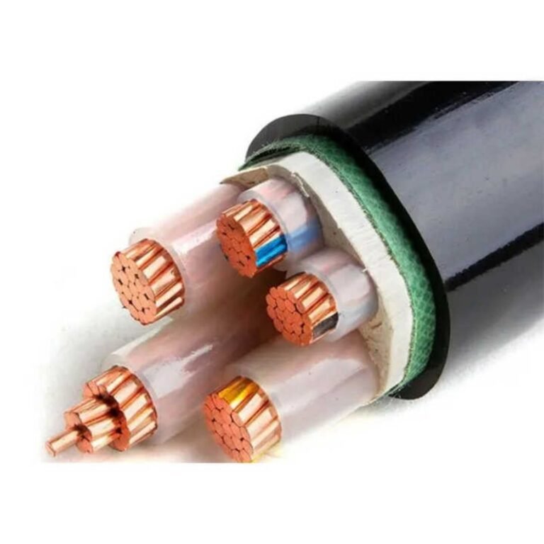
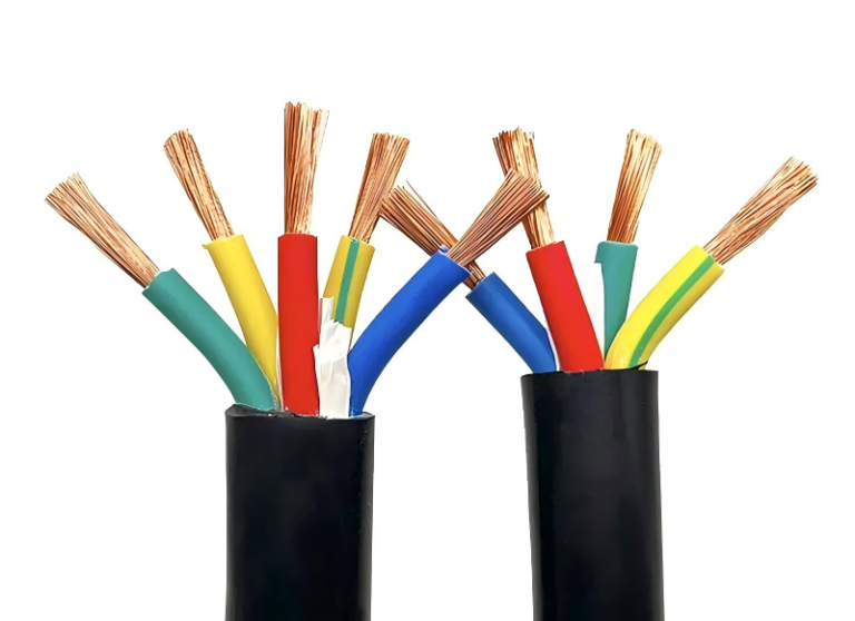
Armored cable earns its reputation on the plant floor — crush resistance, rodent protection, mechanical robustness in places where unarmored cable simply wouldn’t survive a month. But that same armor creates real problems once you move past the “is it tough enough?” question and into installation scheduling, routing constraints, termination budgets, and total installed cost. Procurement teams that spec SWA across the board because it feels safer often end up absorbing labor overruns, scrapped termination attempts, and routing headaches that nobody priced into the original bill of quantities.
Armored cable’s main disadvantages are its significantly higher weight and stiffness, elevated installation labor costs (typically 25–40% above unarmored equivalents), more demanding termination hardware, and restricted bend radius — usually 6–8× overall diameter — that limits routing flexibility. In corrosive or high-vibration environments, the armor itself can become a liability rather than an asset.
What’s worth understanding is that none of these disadvantages are dealbreakers in isolation — most experienced engineers know SWA has a weight penalty and plan around it. The problems tend to stack. A cable tray gets overloaded because someone underestimated SWA’s mass per meter; the revised tray spec delays the civil subcontractor; the termination glands weren’t ordered in the right size for the actual cable OD. Each issue is manageable alone, but together they chew through schedule and contingency faster than almost any other single material decision on a project.
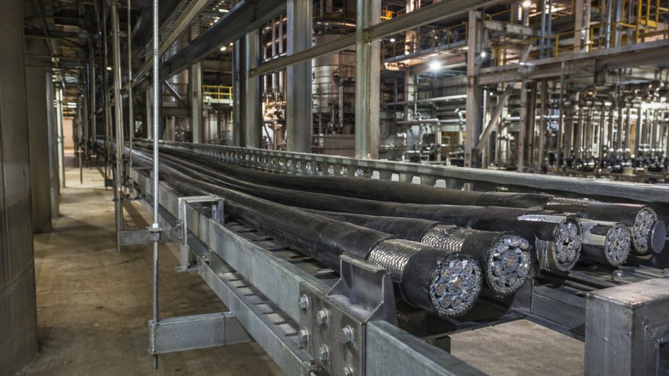
Higher Material and Unit Cost: How Armor Layers Drive Up Cable Procurement Budgets
The armor itself isn’t free, and neither is the steel wire drawn, galvanized, and helically wound around your cable before it ever leaves the factory. Procurement teams who budget for armored cable using unarmored pricing as a baseline — then apply a rough percentage uplift — routinely underestimate project costs by a meaningful margin. The premium is real, it compounds across terminations and accessories, and it shifts with commodity markets in ways that unarmored cable pricing simply doesn’t.
The Per-Meter Cost Premium Across Conductor Sizes
At the smaller end of the range — say, a 4-core 2.5 mm² cable — the armor premium is proportionally the most painful. The conductor material cost is low, so the steel wire armor represents a large share of total cable cost; expect the armor to account for roughly 25–35% of the unit price at that cross-section. At 16 mm², the ratio moderates somewhat, typically 20–30%, because the conductor copper or aluminum now dominates more of the bill of materials. By the time you reach 95 mm² or 240 mm², armor cost as a share of total unit price drops toward 15–20%, though the absolute per-meter cost difference is still significant on a large procurement volume. A 240 mm² 4-core SWA cable in copper might run 12–18% more per meter than its unarmored XLPE equivalent, depending on steel wire gauge and sheath specification — but when you’re buying 10,000 meters of it, that delta funds a lot of other project line items.
The armor layer typically represents 15–35% of total armored cable unit cost depending on conductor cross-section and steel wire gaugeTrue
At small conductor sizes, low copper/aluminum content makes armor a proportionally large cost component; at large cross-sections, conductor material dominates and the armor share decreases, though absolute cost remains significant
Raw Material Volatility Compounds Budgeting Risk
Low-carbon steel wire and galvanized steel tape prices track global steel markets, which means they can swing 15–30% within a 12-month window under normal commodity cycle conditions — and more during supply disruptions. Unarmored cable pricing moves with copper and aluminum, which are volatile enough on their own, but at least copper hedging instruments are liquid and widely used. Steel wire for cable armor is a niche sub-product; most procurement contracts don’t carry price escalation clauses that specifically cover it. For any project where cable procurement spans 18–36 months — phased industrial builds, infrastructure rollouts, long-lead export orders — this creates genuine exposure. A fixed-price cable supply contract signed at project kickoff can look very different by the time Phase 3 deliveries are due.
The Accessories Nobody Budgets Properly
Here’s where projects routinely bleed cost: armor-compatible termination hardware. SWA glands — brass or stainless depending on environment, in IP66 or IP68 rated variants — run meaningfully more than standard cable glands. On a large MCC panel or a distribution board with 40 or 60 cable entries, the gland cost alone can add several thousand dollars to what initially looked like a straightforward installation budget. Add armor clamps, bonding conductors, earth tags, and the labor to properly terminate each one, and the accessory cost per termination point accumulates fast. In practice, I’ve seen this line item get budgeted at roughly half its actual value on first-pass estimates.
Aluminum Wire Armor and International Procurement Complications
AWA cable is lighter than SWA — useful for overhead or weight-constrained installations — but aluminum wire currently commands a price premium over steel wire in most markets, which partially offsets the weight saving. Then there’s interlocked armor (MC-style cable common in North American specifications): the manufacturing process is different, the armor profile is different, and the gland hardware isn’t interchangeable with SWA fittings. Engineers sourcing cable internationally need to confirm which armor construction the specification actually requires, because quoting SWA against an MC-cable spec — or vice versa — produces pricing that’s incomparable and can derail procurement approvals mid-project.
Increased Weight and Handling Difficulty: Structural and Logistical Burdens on Site
Steel wire armour adds real mass. That’s obvious in principle, but engineers routinely underestimate how quickly it compounds into a logistical and structural problem once you’re talking about long runs, elevated routes, or congested sites where every kilogram of cable has a knock-on cost.
Weight Grows Faster Than You’d Expect at Larger Cross-Sections
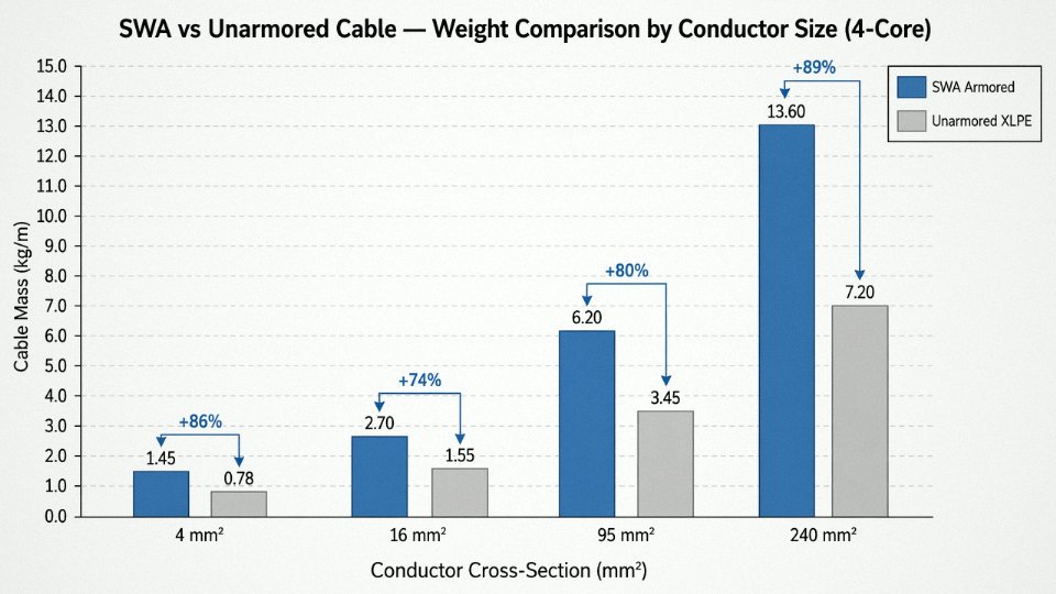
The 30–60% weight penalty of SWA over unarmored thermoplastic cable isn’t uniform across the conductor range — it skews heavier as cross-section increases. A 4-core 4 mm² SWA cable might run around 0.28–0.32 kg/m versus roughly 0.19–0.22 kg/m unarmored. That gap feels manageable. Push up to 4-core 95 mm² and the SWA equivalent typically lands in the 3.2–3.8 kg/m range depending on insulation type and armour wire gauge, compared to around 2.1–2.5 kg/m for an unarmored XLPE equivalent. The weight differential itself is now over 1 kg per meter.
A 500 m run of 4-core 95 mm² SWA — not an unusual run length for a substation cable or main feeder in a process plant — can weigh upward of 1,600–1,900 kg on the drum, and that’s before you account for the drum itself. At 185 mm² the numbers get worse fast. In practice, this means a run that looks like a single-drum job on a drawing can turn into a two-drum, two-pull operation with an intermediate joint, adding both material cost and schedule days.
A 500 m run of 4-core 95 mm² SWA cable can weigh over 1.5 tonnes of cable mass alone, excluding the drum.True
At approximately 3.2–3.8 kg/m for 4-core 95 mm² SWA, a 500 m run yields 1,600–1,900 kg of cable, consistent with standard manufacturer weight data for this conductor/armour combination.
Drum Handling Logistics Cascade Into Equipment Hire Costs
Heavy armored cable requires larger drum diameters to maintain bending radius limits. Larger drums mean you need a heavier-duty drum jack — the lightweight A-frame stands common on general electrical contracting sites won’t handle a 1.5-tonne drum safely. On delivery, a flatbed with a crane-offload or a rough-terrain forklift with adequate rated capacity becomes a requirement rather than a convenience. Sites that didn’t budget for crane hire at the cable pulling stage sometimes find out the hard way. Equipment hire rates for a 5–10 tonne rough-terrain telehandler or mobile crane on a construction site typically add anywhere from a few hundred to over a thousand dollars per shift depending on region and availability, and if the schedule slips, those costs multiply.
Cable Tray and Support Structure Load Calculations
SWA cable’s dead load forces a structural rethink on tray and ladder rack design. Standard support spacing for medium-duty cable tray is often quoted at 900 mm in manufacturer literature. For heavily loaded SWA runs — especially where multiple large-section cables share a tray — that spacing may need to drop to 600 mm or even less to stay within the tray’s rated load per span. That means more brackets, more steelwork, more fabrication hours, and more anchor points into walls or structure. On a large plant with kilometers of cable routes, the additional steelwork cost can be surprisingly significant. It’s the kind of line item that gets missed in early-stage estimates because the tray supplier’s standard schedule gets used without checking actual cable weights.
Offshore and Vertical Installations Are Where Weight Becomes a Real Constraint
On an oil platform, a wind turbine tower, or a high-rise building riser shaft, gravity stops being abstract. Vertically installed cables carrying their own weight develop tension at the top cleats — tension that increases with every meter of unsupported run. SWA cables in these applications often require intermediate cleating at intervals of 500–800 mm rather than the 900–1,500 mm spacings used for horizontal runs, depending on cable weight, conductor cross-section, and the cleat manufacturer’s load tables. Pulling eyes and pulling socks need to be rated for the full suspended weight plus dynamic load during installation, and that hardware isn’t cheap or fast to fit correctly. On offshore projects in particular, where mobilization costs mean every extra labor hour is expensive, the additional cleating and the extra pull equipment translate directly into installation cost per meter that can rival or exceed the cable unit cost itself on large-conductor vertical drops.
Rigid Construction and Inflexible Routing: How Armor Limits Cable Layout in Complex Installations
Steel wire armor doesn’t just add weight — it fundamentally changes how a cable behaves when you try to route it around real infrastructure. That distinction matters enormously once you’re on site trying to feed cable through a congested switchroom or retrofit a run through trays that were designed twenty years ago for smaller, lighter, more flexible cables.
Minimum Bending Radius: Where the Numbers Become a Site Problem
IEC 60502-1 and BS 5467 both specify minimum bending radii for armored cables in the range of 6–8× the overall cable diameter, with the exact multiplier depending on cable construction (SWA, STA, number of cores, and overall diameter). Unarmored flexible cables typically sit at 4–6× overall diameter. That gap sounds modest on paper. In practice, on a 4-core 35 mm² SWA cable with an overall diameter of roughly 28–32 mm depending on insulation type, you’re looking at a minimum bend radius somewhere between 170 mm and 256 mm — a sweeping arc that demands real estate inside a panel or at a conduit entry point. A comparable unarmored cable can make that same turn in noticeably tighter quarters.
The consequence is cascading: longer cable routes to achieve compliant bends, larger entry knockouts or gland plates on switchgear, and in some cases a completely redesigned cable path to avoid a 90-degree entry that an unarmored cable would have handled cleanly. In cramped substation cable cellars or the lower marshalling zones of motor control centers, that translation from radius specification to physical routing geometry is where project schedules quietly slip.
Retrofit Installations: Stiffness Meets Reality
Retrofit work punishes armored cable more than new-build does. Existing cable trays were filled to some original layout plan; by the time a plant is ten years old, those trays are typically carrying 60–80% of their nominal load capacity and the available routing paths are not straight. Threading SWA through a partially occupied tray with multiple direction changes requires far more force than most installers expect, and in tight horizontal duct sections, the cable’s resistance to bending can make the pull effectively impossible without partially dismantling tray cover sections or removing adjacent cables temporarily — both of which carry their own risks in an energized facility.
Terminating in confined junction boxes is similarly frustrating. The cable simply won’t hold the position you need it in while you work the gland and dress the conductors. Experienced installers know to leave extra length specifically for this reason, but that practice isn’t universal, and a run planned tight to budget will create grief at both ends.
Sub-Minimum Bending: The Failure You Won’t See Until It’s Too Late
Sharp bends applied to SWA cable during installation can damage wire armor strands and create stress concentration points on the insulation beneath, leading to faults that may not appear immediately but can develop over months or years in service.True
Mechanical deformation of armor wire strands at an over-bent section creates localized pressure on the underlying bedding and insulation. The damage is internal and visually undetectable after installation; insulation resistance testing at commissioning may still pass because the damage hasn't yet progressed to breakdown voltage. Field failure investigations on aged SWA cables frequently find over-bent sections as the fault origin.
Installers who spend most of their time on flexible unarmored cable develop muscle memory for tight bends. When they move to SWA without specific briefing, sharp bends happen — usually at conduit entries, at the last foot before a gland, or where cable is dressed into a tray corner. Broken or kinked armor wires at that point do two things: they concentrate mechanical stress onto the insulation directly beneath, and they open pathways for moisture ingress along the armor layer, accelerating corrosion in the one location where the armor is already compromised. Earth continuity through the armor may be reduced without any visible indication. You won’t find it with a basic insulation resistance test at commissioning. It shows up later, sometimes years later, as an intermittent fault or an unexplained trip.
Aluminum Wire Armor: Marginally Better, Still Constrained
AWA cable does offer slightly better flexibility than SWA in equivalent sizes — aluminum wire is less stiff than steel — but the improvement is incremental, not transformational. In small conduit work or tight equipment enclosures, AWA still presents real routing difficulties. Neither AWA nor SWA approaches the routing versatility of liquid-tight armored flexible conduit systems in highly congested environments or on vibrating equipment like compressors and large motors, where even compliant rigid bends will fatigue over time. For those applications, the armor is genuinely the wrong answer regardless of its other merits.
Complex Termination and Jointing Requirements: The Skilled Labor and Time Cost of Proper Armor Connections
Terminating an SWA cable correctly is not difficult if you know what you’re doing — but that qualifier matters more than most specifications acknowledge. On a busy industrial fitout, you’ll have multiple trades working simultaneously, time pressure, and sometimes a sparky who’s competent with standard cable but hasn’t done armored work in six months. That’s where things go wrong quietly, in ways that don’t show up until something fails in service.
The Termination Sequence and Why Each Step Has Consequences
The correct termination of a steel wire armored cable involves somewhere between 8 and 12 discrete steps depending on gland type and installation conditions. You strip the outer sheath to an accurate length — too short and the gland body won’t grip the armor properly; too long and exposed armor wires create a snagging and corrosion risk. The armor wires get fanned out evenly, trimmed to the correct length for the specific gland being used, then folded back over the armor cone. The gland body goes in over the inner sheath, the cone seats against the wire layer, and the gland nut gets torqued to the manufacturer’s specified value — not guessed at by feel. Finally, an earth tail or earth tag connects the gland body to the enclosure or earth bar, completing the protective conductor path through the armor.
Compare that to terminating an unarmored cable under a standard compression gland: strip outer sheath, insert cable through gland, tighten. Three steps, maybe four if you’re being careful about bend relief. The labor time difference is real. Installation labor costs for armored cable systems typically run 25–40% higher than unarmored equivalents, and a significant portion of that premium comes directly from termination time, not just the pulling or tray work.
Earth Continuity Bonding — The Step Most Often Skimped
The armor in an SWA cable isn’t just mechanical protection. Under BS 7671 and equivalent standards, it qualifies as a protective conductor, meaning it must be bonded to earth to fulfill that function. At minimum, bonding at one end is required; longer runs, or systems using single-point bonding or cross-bonded schemes to control circulating currents, require carefully considered bonding at both ends with the scheme documented.
Loose or omitted armor bonding is one of the more common defects found during post-fault investigations on installed industrial systems. The consequences are not minor — unbonded armor can float to a dangerous voltage under fault conditions, and partial contact corrosion at an unbonded gland can progress undetected for years before the armor’s mechanical integrity is compromised. In wet or chemically active environments, the deterioration accelerates considerably.
Incorrect or missing armor earth bonding is one of the leading causes of shock hazard in SWA cable installationsTrue
Under fault conditions, an unbonded armor layer can rise to near full fault voltage relative to earth. This is well-documented in electrical safety incident investigations and is the reason bonding requirements are explicitly mandated in BS 7671 and IEC wiring standards.
Gland Selection Is Its Own Engineering Task
Picking the right gland is not a purchasing afterthought. Gland type — A1, A2, B, CW, BW per BS 6121 — depends on whether you need a seal on the outer sheath, the inner sheath, or both. Thread form (metric, PG, or NPT) has to match the enclosure entry. Body material matters in corrosive or classified environments: standard brass is fine for a dry indoor panel; nickel-plated brass or 316 stainless becomes necessary in marine locations, food processing areas, or Zone 2 hazardous areas.
The gland also has to match the actual cable OD, which has a manufacturing tolerance band — not a single value. Buy glands sized to the nominal OD without checking the actual cable you received, and you’ll find out on site that the armor cone doesn’t seat correctly. This isn’t hypothetical; it happens on projects where cable and glands are procured from different sources without cross-referencing the actual dimensional data sheets.
Mid-Run Joints: Where Field Workmanship Really Gets Tested
Straight-through joints in armored cable runs are significantly more demanding than equivalent joints in unarmored systems. The joint must restore the full mechanical protection of the armor layer, maintain the earth continuity path through the splice, and provide environmental sealing appropriate to the installation duty. Factory-assembled heat-shrink or cold-shrink through-joint kits include armor reinstatement sleeves — typically a woven wire braid or pre-formed steel mesh — specifically to restore that continuity. The kits from reputable suppliers are well-engineered, but they require the installer to follow a precise sequence, and they’re not cheap, running from roughly $40 to well over $200 per joint depending on cable size and kit specification.
Field-made joints that skip the armor reinstatement step — or bond it sloppily with a cable tie and a wing nut — are a recurring finding in post-fault cable investigations, particularly in utilities and older industrial plants. The insulation system inside might be perfectly intact, but mechanical failure of the armor at the joint point, or loss of earth continuity through an unrestored splice, creates a genuine hazard and typically voids any warranty on the cable itself.
The practical takeaway for project teams is straightforward: budget the training, budget the correct gland selection process, and treat jointing as a hold point for inspection rather than a task that gets signed off in a block with everything else.
Corrosion Vulnerability of the Armor Layer: Long-Term Degradation in Wet, Chemical, and Coastal Environments
Steel armor is specified to protect cables. That’s the whole point. So it tends to catch engineers off guard when the armor itself becomes the failure mechanism — quietly degrading for years before any symptom appears at the cable’s outer surface. In aggressive environments, this isn’t a remote edge case. It’s a well-documented failure mode that shortens service life and, in buried applications, often goes completely undetected until a fault occurs.
How Corrosion Gets Into the Armor Layer
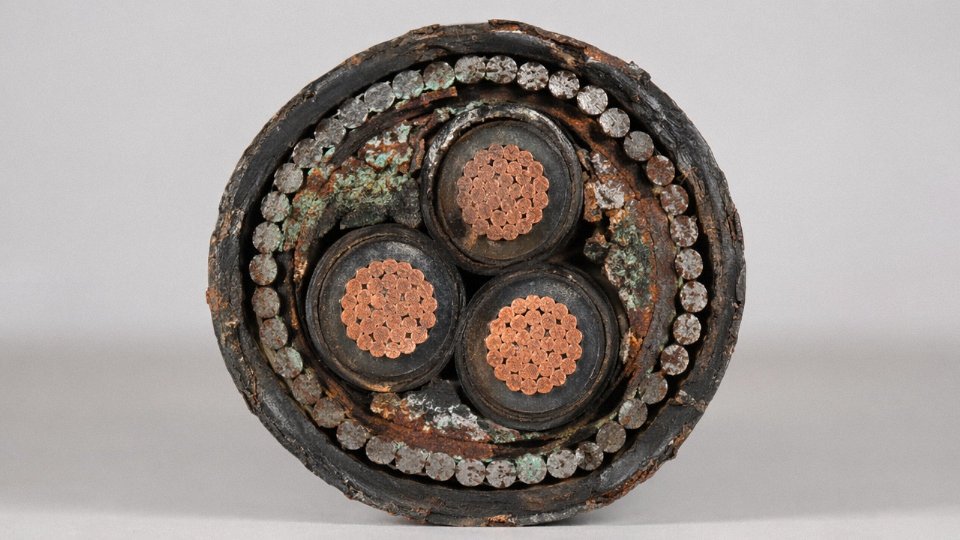
The degradation sequence is fairly predictable once you understand it. SWA construction relies on a zinc galvanizing layer on each steel wire to provide sacrificial corrosion protection. That galvanizing works well in dry, stable conditions. In wet environments — particularly where sheath damage or an inadequately sealed gland allows moisture ingress — the zinc oxidizes relatively quickly, and once it’s gone, red-iron-oxide corrosion of the underlying steel begins in earnest. At that stage, the mechanical protection the armor was specified to provide is being progressively destroyed from the inside out.
In coastal installations, the combination of salt-laden humidity, temperature cycling, and the occasional condensation event inside cable trays creates near-ideal conditions for this process. Industrial environments with airborne chlorine compounds, acid mist, or ammonia vapors are similarly aggressive. Under these conditions, a cable that would reasonably be expected to deliver 30 or more years of service can be structurally compromised in under a decade — sometimes considerably less, depending on sheath integrity and gland quality. In my experience, poorly specified or incorrectly torqued glands are the single most common entry point for moisture, and the corrosion that follows is rarely caught until someone pulls a routine inspection and finds wire armor that crumbles when touched.
Direct Burial: The Hidden Threat Below Grade
Above-ground corrosion is at least visible in principle. Buried cable is a different problem. Soil chemistry varies enormously across a single site, let alone across a project spanning hundreds of meters, and the conditions that accelerate armor corrosion — acidic soils with pH below roughly 6, heavy clay with high moisture retention, fill contaminated with industrial residues — are not always identified during initial geotechnical work.
Stray DC currents deserve particular attention. Near electrified rail infrastructure, or anywhere cathodic protection systems are operating on adjacent metallic structures, stray currents can drive electrochemical corrosion at specific points along the armor in a pattern that has nothing to do with soil chemistry and everything to do with current gradient. This type of corrosion is highly localized, aggressive, and essentially invisible without either periodic excavation or metallic sheath monitoring equipment. Most sites do neither on a routine basis.
Direct burial SWA cable in acidic or stray-current-affected soils can suffer significant armor degradation within 5–10 years without any visible indication at the outer sheath surface.True
Soil-side corrosion attacks the armor layer while the polymeric outer sheath may remain visually intact. Without excavation or electrical monitoring, the degradation goes undetected until mechanical or electrical failure occurs.
Why Steel Tape Armor Corrodes Faster
STA construction — steel tape rather than wires — is meaningfully more vulnerable, and it’s worth being explicit about why. The overlapping tape configuration creates narrow crevice zones between layers where moisture gets trapped and oxygen levels drop, establishing exactly the differential aeration conditions that accelerate crevice corrosion. Because the steel tape has a much smaller cross-section than equivalent SWA wire, even moderate material loss translates quickly into a real reduction in crush and impact resistance. The outer sheath typically shows no indication of this. You can have a cable that looks fine externally and has lost a substantial fraction of its mechanical protection.
Specifying Appropriate Corrosion Protection
The practical response depends on the environment severity. For direct burial in aggressive soils — acidic, clay-heavy, or chemically contaminated ground — double-sheathed SWA (an additional bedding or oversheath between the armor and the outer jacket) significantly slows moisture access to the armor wires and should be a default specification rather than an upgrade discussion.
For single-core AC cables in coastal or marine environments, aluminum wire armor (AWA) is often the better choice. Aluminum forms a stable, adherent oxide layer that resists further corrosion without sacrificial consumption of the base metal. It’s lighter than steel armor, which helps with the weight penalties covered earlier in this article, and it avoids the induced-current concerns that make steel armor problematic on single-core AC conductors anyway.
For genuinely extreme chemical duty — a chlor-alkali plant, a fertilizer facility, somewhere with continuous acid or solvent exposure — glass fiber braid armor or stainless steel armor variants are available and worth specifying, even at the higher unit cost, because replacing a corroded buried cable run is orders of magnitude more expensive than the armor upgrade would have been. Jinda’s engineering team routinely assists with site-specific corrosion assessments that translate soil reports, environmental data, and installation geometry into a concrete armor and sheath specification. That step gets skipped more often than it should.
Earthing, EMI Shielding Confusion, and Electrical Interference Risks in Signal and Power Mixed Installations
Steel wire armor does two things reasonably well: it resists mechanical damage, and it provides a fault current return path. What it does not do — despite what a surprising number of specifications imply — is act as a proper electromagnetic shield. Conflating those two functions is one of the more expensive wiring mistakes you can make in an instrumentation-heavy facility, and it shows up on the plant floor as unexplained relay trips, drifting 4–20 mA signals, and PLC alarm floods that the controls team spends weeks chasing.
Armor as Earth Conductor vs. Armor as EMI Shield
Per IEC 60364-5-54, the steel wire armor of a multicore cable can legitimately serve as a protective earth conductor, provided the cross-sectional area of the armor wires meets the minimum adiabatic requirement for the upstream fault level. That function is real and useful. The confusion arises when engineers assume that because the armor surrounds the conductors, it must also be screening them against electromagnetic interference.
It isn’t. SWA armor is constructed from individual steel wires laid helically around the cable core. That helical, non-continuous geometry is about as far from a Faraday cage as you can get while still calling something a “surrounding layer.” The coverage gaps, the resistivity of steel relative to copper or aluminum, and the lack of a low-impedance circumferential return path all combine to make SWA armor essentially transparent to high-frequency interference. Measured shielding effectiveness for typical SWA construction runs somewhere in the 10–20 dB range at frequencies above a few kilohertz — compared to 60–90 dB for a purpose-built foil-and-drain-wire screened instrumentation cable. Specifying SWA in place of properly screened cable for thermocouples, RTDs, HART loops, or fieldbus segments is not a conservative choice. It just looks like one on paper.
Circulating Currents in Single-Core SWA — A Sizing Trap
Single-core SWA cables carrying AC current present a different problem entirely. The alternating magnetic field from the conductor induces circulating currents in the steel armor — a continuous metallic loop around each cable. Those currents cause real I²R heating, and the practical consequence is an ampacity derating that typically runs 10–20% compared to an equivalent multicore SWA arrangement, though the exact figure depends on load current magnitude, cable spacing, whether armor ends are bonded at one point or both, and laying arrangement (flat formation vs. trefoil). For a 240 mm² single-core SWA feeder to a large motor or MCC, that derating is not a rounding error. Size the cable ignoring it and you’ll run hotter than your insulation class allows, shortening cable life and potentially tripping thermal protection under sustained full-load conditions.
Single-core SWA cables experience significant ampacity derating due to armor circulating currents under AC loadingTrue
The helical steel armor forms a closed magnetic circuit around a single-core AC conductor, inducing eddy and circulating currents that generate additional heat, requiring derating per IEC 60502 and cable manufacturer published correction factors.
The standard engineering response is to use aluminum wire armored (AWA) cable for single-core applications. Aluminum has far lower magnetic permeability than steel, which dramatically reduces induced losses. It is not a zero-loss solution, but the derating is substantially smaller and more manageable in sizing calculations.
Stray Currents and Mixed-Tray Interference
In process plants, power and signal cables often share the same tray routes — especially in retrofit projects where tray space was never planned with segregation in mind. Steel-armored power cables with inconsistent or missing armor earth bonds become magnetic noise sources. Measured interference voltages in adjacent instrumentation cables under these conditions can reach 10–50 mV, depending on load current, cable spacing, and whether bonding is at one end or floating entirely. That noise floor is more than enough to corrupt a 1–5 V analog signal, generate spurious counts on a pulse input, or push a fieldbus segment into repeated retries.
The fix is not complicated but it requires discipline at installation: segregate cable trays by signal class per IEC 61918 or your applicable national standard, bond armor consistently and at the correct points, and never substitute armor for a dedicated screened cable on any circuit where signal integrity matters. If the tray layout cannot achieve adequate physical separation — 300 mm is a common minimum, though the standard depends on voltage class and signal sensitivity — use screened instrumentation cable with its own drain wire and treat the armor, if present, solely as a mechanical and earth-fault protection layer.
Repair, Fault Location, and End-of-Life Challenges: What Happens When Armored Cable Needs Attention After Installation
Once armored cable is in the ground or cast into structure, the real cost of specifying it often becomes apparent — not during commissioning, but years later when something goes wrong.
Fault Location Is a Specialist Job, Not a Maintenance Task
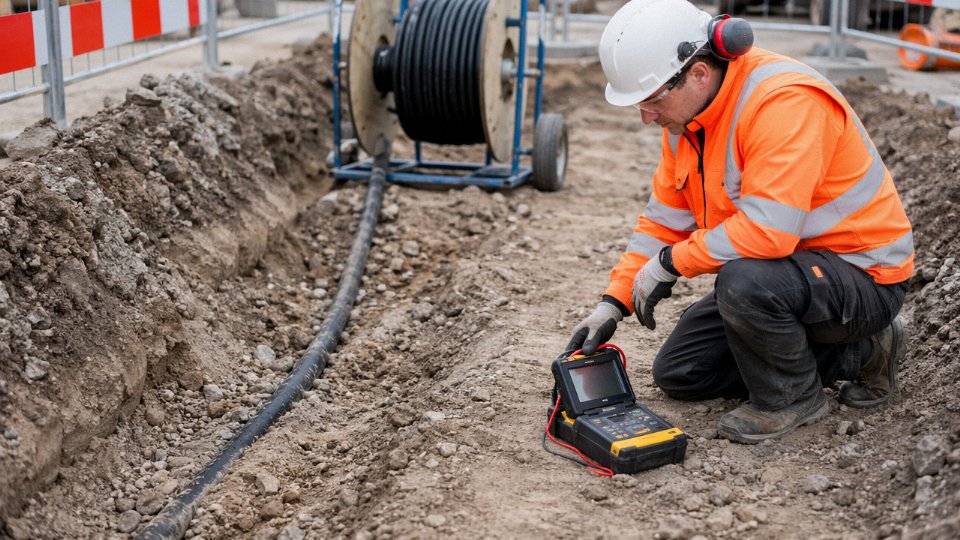
Finding a fault in an unarmored cable in a surface-mounted trunking system is, comparatively, straightforward. Armored cable buried at 600 mm or embedded in a concrete slab is a different problem entirely. The steel wire or steel tape armor layer has its own electrical characteristics — finite resistance, capacitance to the conductors, and an impedance profile that interacts with test signals in ways that general maintenance electricians are simply not trained to interpret.
Time-domain reflectometry (TDR) works on armored cable, but the armor’s distributed impedance can blur reflections, particularly on shorter runs or where the fault is high-resistance rather than a clean dead short. Murray loop tests require the tester to account correctly for the armor’s contribution to the loop resistance, or the calculated fault distance will be wrong — sometimes badly wrong. In practice, the faults that develop under damaged armor tend to be the slow-burn kind: water ingress tracking along the armor interstices, mechanical damage to the insulation that creates a partial discharge or a megohm-range fault rather than a solid earth. These require power-frequency withstand testing, VLF (very low frequency, typically 0.1 Hz) hipot equipment, or DC sheath integrity testers — instruments that most in-house maintenance teams don’t carry and that specialist contractors charge accordingly for mobilizing. A fault-find campaign on a single buried SWA run can realistically consume one to three days of specialist time before the excavation crew even arrives.
Field Repair: The Hours Add Up Quickly
A compliant field repair joint on a damaged SWA cable requires reinstating the armor continuity, restoring full insulation integrity, and resealing the outer sheath to the original mechanical protection classification.True
Standards including IEC 60364 and BS 7671 require that cable joints maintain at least equivalent protection to the original cable construction; armor reinstatement kits exist specifically because skipping the armor reinstatement step leaves the joint mechanically and electrically non-compliant.
Proprietary armor reinstatement kits — the stainless braid sleeves, resin pours, or mechanical clamp assemblies depending on which system you’re using — are not complicated in principle, but they demand two qualified cable jointers working carefully. A realistic time estimate for a single compliant joint on a 4-core 16 mm² SWA: three to six hours, accounting for insulation preparation, heat-shrink or cold-applied joint body application, armor reinstatement, outer sheath repair, and a post-joint insulation resistance check. A pre-formed joint on an equivalent unarmored XLPE cable in a dry environment? Thirty to sixty minutes for one competent electrician. That differential compounds fast if the fault diagnosis was wrong and you’re opening a second location.
The Embedded Cable Problem
SWA cast into a power-float concrete floor — common in logistics facilities and food processing plants — is essentially permanent. The armor’s rigidity means there is no possibility of pulling the cable through and replacing just a damaged section the way you might with a conduit system. A single insulation fault in a 40-meter embedded run usually forces a complete cable replacement: core drilling, chasing, or full slab break-out depending on the installation geometry, followed by re-embedding new cable or, if the disruption is unacceptable, abandoning the embedded run entirely and surface-mounting a replacement. The cost difference between a conduit-based unarmored system and direct-embedded SWA isn’t visible at installation but can be severe when the building is operational and production cannot stop for structural remediation work.
End-of-Life and Sustainability Considerations
Decommissioning SWA cable is messier than the recycling industry usually acknowledges. The copper conductors have obvious scrap value and go to copper recyclers without controversy. The steel armor is recyclable too, but separating it cleanly from the cross-linked polyethylene or PVC insulation and the polymer bedding and fillers requires mechanical stripping — the mixed-material construction means armored cable doesn’t go through the same simple granulation process as a plain copper-insulated wire. Cable recycling facilities that aren’t set up for it will downgrade the batch or charge a processing premium.
Older installations — anything pre-2000 in many European and Asian industrial facilities — may contain SWA cables with PVC sheaths compounded with legacy plasticizers or, in some cases, early halogenated flame-retardant compounds that require separate disposal streams under EU WEEE and RoHS frameworks. This is increasingly a procurement and ESG reporting concern rather than a theoretical one: circular economy frameworks in the EU and the UK’s Streamlined Energy and Carbon Reporting requirements are pushing procurement teams to document end-of-life material flows at the point of specification, not retrospectively. Choosing SWA over a halogen-free armored alternative, or over an unarmored LSZH system in a suitable application, may carry a documentation and disposal cost that doesn’t appear on the original capex spreadsheet.
The lifecycle picture, in short, is rarely as clean as the installation-phase comparison suggests. Armored cable earns its place in direct-buried, high-mechanical-risk, and outdoor industrial applications. But in environments where future access, repairability, and end-of-life recyclability are live concerns, the armor layer that protects the cable on day one can quietly generate significant cost and complexity over a ten- or twenty-year asset life.
Frequently Asked Questions About the Disadvantages of Armored Cable
Is armored cable always required for underground installation?
No — and this is probably the most common over-specification mistake on mid-scale projects. HDPE or rigid PVC conduit systems carrying unarmored XLPE or PVC-insulated cable are widely accepted for direct underground runs under IEC 60364 and most national derivatives. Mechanical protection comes from the duct, not the cable jacket, which means you get simpler terminations, lower cable unit cost, and — critically — the ability to pull and replace individual cables without excavation. SWA direct burial genuinely earns its place when trenching is so constrained that conduit installation isn’t practical, or when a site risk assessment flags a high probability of repeat excavation damage (think urban cable routes crossing active construction zones, or agricultural land with deep tillage). Outside those scenarios, defaulting to SWA underground is often a budget decision dressed up as a technical one.
Can armored cable be installed in hazardous (explosive atmosphere) locations?
Yes, but the gland selection is where projects get into trouble. Zone 1 and Zone 2 classified areas under IEC 60079-14 require ATEX/IECEx certified barrier glands — specifically designed to prevent flame propagation back through the cable entry into the enclosure. The cable itself must also be verified against the temperature class (T-rating) and gas group of the classified area. What inspectors and insurance auditors routinely flag in practice is the use of standard SWA glands — perfectly fine for general industrial work — installed in hazardous areas because someone on site pulled from the wrong materials bin. That single substitution can void the enclosure’s Ex certification entirely. If you’re procuring cable for a mixed facility with both safe and classified zones, keep the gland specs clearly separated in your BOM.
Standard industrial SWA cable glands installed in ATEX Zone 1 areas without certified barrier glands constitute a safety non-compliance under IEC 60079-14 and can void Ex enclosure certification.True
IEC 60079-14 requires cable entry devices in classified areas to maintain the protection concept of the enclosure, including flame-path integrity; standard SWA glands provide no such barrier and are not ATEX/IECEx certified for this purpose.
Does the steel armor serve as the protective earth conductor?
It can, under specific conditions. IEC 60364-5-54 permits armor to function as a protective conductor (CPC) provided the cross-sectional area of the armor meets the minimum CPC sizing calculation and the designer has verified impedance of the armor earth path — including the resistance through glands and bonding conductors at every termination. In practice, many experienced designers won’t rely solely on armor as the CPC for critical circuits: a single corroded gland connection introduces resistance that may prevent rapid fault clearance. Specifying cables with a dedicated earth core alongside the armor costs a little more upfront and is worth it on anything feeding switchgear, process-critical motors, or life-safety circuits.
Why does armored cable installation cost more per meter than unarmored?
Several compounding factors. Every termination requires an SWA gland (versus a simple cable gland), an armor bonding conductor, and an earth tag — none of which are trivial to source or install correctly. Termination time per point runs roughly 3–5× longer than unarmored equivalents, depending on cable size and the installer’s familiarity with the specific gland type. Add specialized armor-cutting tools, stricter bending radius compliance during pull-in, and the need to dress armor wires cleanly under the gland back-nut, and skilled-labor hours per circuit climb fast. On a large project with hundreds of terminations, that labor differential — typically 25–40% higher total installation cost than equivalent unarmored cable — matters more than the cable unit price difference.
What service life should I expect compared to unarmored cable?
In dry, temperature-stable indoor environments, both constructions can realistically reach 30–40 years with correct installation. The comparison gets uncomfortable in wet or buried conditions. Once an SWA outer sheath is breached — by ground movement, rodent attack, or a nick during installation — moisture reaches the steel armor and corrosion begins. An unarmored cable in intact HDPE conduit, by contrast, is still protected as long as the duct is sound. For high-value buried SWA circuits, sheath integrity monitoring (time-domain reflectometry or sheath resistance testing at commissioning and during scheduled maintenance) is worth building into the asset management plan rather than discovering the problem when an insulation fault shows up years later.
When does aluminum wire armor make more sense than steel?
AWA is the right call for single-core large-conductor cables — the non-magnetic aluminum armor avoids the circulating current losses that steel armor induces in single-core AC circuits, which can be measurable on conductors above roughly 95–120 mm² depending on load current and run length. Coastal and marine environments favor AWA because steel corrosion risk under compromised sheathing is significantly elevated near salt air or splash zones. Weight-critical installations — offshore topsides, elevated cable trays in high-bay structures, or any project where tray loading calculations are already tight — also benefit from AWA’s lower mass per meter. SWA retains the edge on crush resistance and cost for standard multi-core industrial runs where the circulating current issue doesn’t apply.
How to Decide Whether Armored Cable Is the Right Choice for Your Project: A Practical Decision Framework
Everything covered in this article points toward the same practical question: is the armor actually earning its cost on your project, or are you paying a 25–40% labor premium plus higher material cost for protection you don’t need?
A structured screen helps. In practice, most specification errors go in one direction — engineers default to armored cable because it feels safer, then the project absorbs avoidable cost, weight, and installation complexity. Running through five factors honestly before you write the specification usually catches that.
The Five-Factor Screening Matrix
Mechanical hazard level is the clearest driver. Direct burial in ground subject to third-party excavation, cable routes crossing under vehicle traffic, plant floors with forklift movement, or any environment with documented rodent pressure — these scenarios genuinely justify armor. A clean raised-floor data hall does not. Score this factor honestly against the actual installation route, not a worst-case imagined one.
Environmental aggression is where the counterintuitive findings from the corrosion section matter. High soil acidity (pH below roughly 5.5), permanent waterlogging, coastal saline atmosphere, or direct chemical splash all score against unprotected steel wire armor unless you’ve specified the appropriate oversheath — typically an extruded PVC or polyethylene bedding and serving system verified against the specific chemical class. If the environment is genuinely aggressive and the armor can’t be adequately protected, a different cable system may outperform armored cable over a 25-year service life.
Total installed cost versus cable-only unit cost is the factor procurement managers most often miscalculate. The armor’s contribution to the cable invoice is visible. The termination labor, the gland kits, the tray derating from added weight, the longer pull schedule — those land elsewhere in the project budget and sometimes don’t surface until the contractor’s variation claims arrive. Build total installed cost into the comparison, not just the per-meter cable price.
Available skilled labor matters more than most project engineers admit. Correct SWA termination — armor earth bonding, gland torque, bedding cuts that don’t nick the insulation — requires training and practice. On remote sites, in developing-market projects, or during labor shortages, the pool of competent cable gland workers is a real constraint. Where that skill isn’t reliably available, a well-designed conduit or trunking system with unarmored cable often delivers better long-term reliability.
Future maintenance access closes the matrix. Buried armored runs in concrete floor slabs, embedded in walls, or under permanent structures carry a fault-location and repair cost that needs to be factored at design stage, not discovered during a plant outage.
Where Armor Clearly Wins
Direct burial in high-traffic areas without conduit. Cable exposed to mechanical impact on production floors. Shore crossings and submarine routes. Mining, tunneling, and quarrying environments. Outdoor industrial yard runs where installing conduit would cost more than the cable itself. In these scenarios the armor’s disadvantages are real but secondary — the mechanical or environmental protection it provides is load-bearing to the design.
Where Unarmored Is the Better Answer
Indoor cable trunking and conduit systems, where the infrastructure itself provides the mechanical protection. Data centers and clean rooms, where SWA weight and rigidity create support design problems. Flexible drops to vibrating motors or pumps, where armor stiffness drives fatigue cracking at the gland. Instrumentation and signal circuits where armor provides no meaningful EMI shielding benefit but adds cost and termination complexity. Congested retrofit projects where the bending radius constraint alone can make armored cable unroutable.
Armor is not inherently superior to unarmored cable — its value is entirely application-dependent, and in several common industrial scenarios, specifying armor adds cost and risk rather than reducing it.True
Armor provides mechanical and limited environmental protection, but introduces weight, rigidity, termination complexity, corrosion risk, and total installed cost penalties that can outweigh its benefits in conduit-protected, indoor, flexible, or signal-circuit applications.
Getting the Specification Right
Jinda’s engineering team works with EPC contractors, utility procurement teams, and plant operators across six continents — and the specification questions they field most often aren’t about whether a cable meets a standard, but whether the right cable type was chosen in the first place. With 37-plus years of manufacturing experience across five production bases and the capability to produce SWA, AWA, STA, and armored instrumentation cables to IEC, BS, ASTM, and project-specific requirements, Jinda can support both standard procurement and custom cable solutions where the application genuinely demands them.
If your project sits anywhere near the borderline cases this article describes — mixed mechanical environments, corrosive soil conditions, mixed power and instrumentation runs, or retrofit constraints that make routing difficult — getting a cable selection review before the specification is locked is worth the time. The cost of changing a cable type on paper is zero. The cost of changing it after materials are shipped is not.