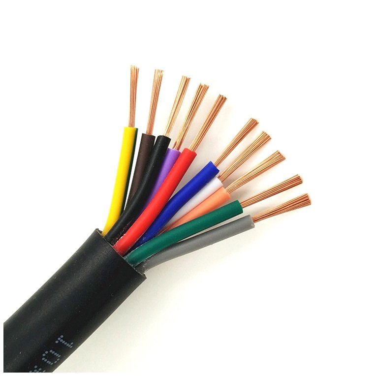
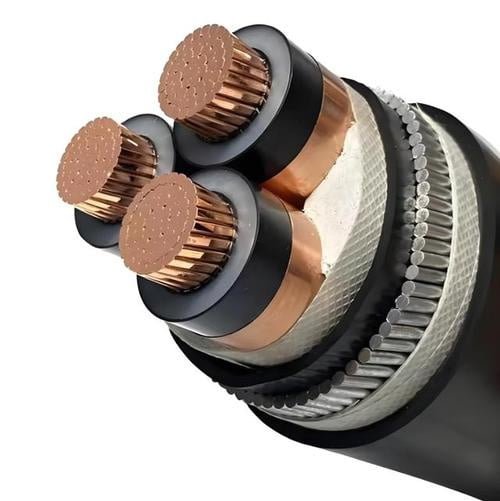
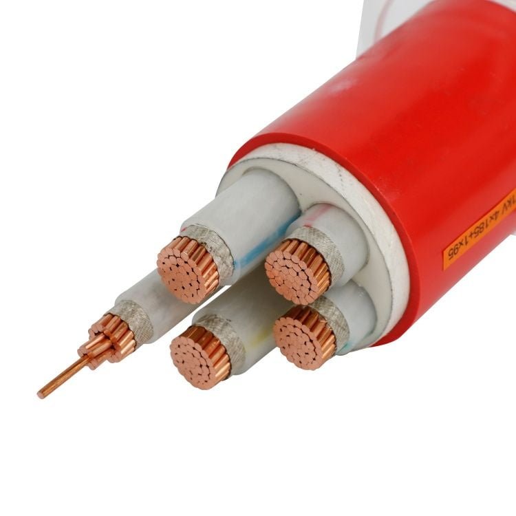
Steel wire armored cable gets specified for good reasons — crush resistance, rodent protection, direct burial — but the armor itself introduces a set of real penalties that catch engineers off guard once installation starts or the first maintenance cycle rolls around. A 4-core 16 mm² SWA run that weighs 1.3 kg/m doesn’t sound dramatic until you’re pulling 400 meters through a cable tray and your pull tension is eating into conductor insulation limits. Weight, bending radius, corrosion susceptibility, termination complexity, and raw material cost all compound each other, and the projects that ignore them early tend to pay in rework, derating headaches, or premature failures in aggressive environments.
Steel wire armored cable’s main disadvantages are its significant weight increase (roughly 20–40% heavier than unarmored equivalents), restricted bending radius that complicates routing in tight spaces, corrosion risk in coastal or chemically aggressive sites if galvanizing quality is poor, more demanding and time-consuming termination methods, and higher upfront material and installation cost compared to alternative cable protection systems.
What makes these drawbacks worth examining carefully is that they don’t all show up at the same point in a project’s life. Some hit during installation; others don’t surface until year two or three, when a maintenance crew opens a junction box in a humid coastal substation and finds rust bloom creeping under a gland. The relationship between armor specification, site conditions, and long-term ownership cost is less straightforward than most data sheets suggest — and the tradeoffs look different depending on whether you’re laying a 10-meter equipment feed or a cross-site 11 kV feeder.
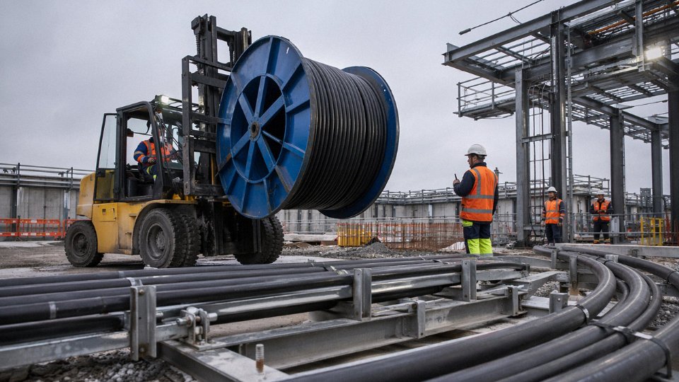
Excessive Weight and Reduced Cable Flexibility Complicate Routing and Handling
Steel wire armor does its job well mechanically — but that job comes at a direct physical cost. The armor layer itself, typically drawn from galvanized low-carbon steel wire wound helically over the inner sheath, adds somewhere between 20% and 40% to the total cable mass compared to an equivalent unarmored design. Where exactly you land in that range depends on conductor cross-section, number of cores, armor wire diameter, and the overall cable OD. A 4-core 16mm² SWA cable running to IEC 60502-1 typically weighs around 1.2–1.5 kg/m; strip out the armor and you’re looking at roughly 0.85–1.0 kg/m for the unarmored equivalent. That gap sounds modest until you’re moving a 500-meter drum.
Weight Penalty Across Common Conductor Sizes
The table below gives approximate installed weight comparisons for typical SWA versus unarmored XLPE multi-core cables. These are representative ranges — actual values vary by manufacturer tolerances, bedding thickness, and armor wire gauge.
| Conductor Size | Cores | SWA Cable (kg/m) | Unarmored XLPE (kg/m) | Weight Increase |
|---|---|---|---|---|
| 1.5 mm² | 4 | 0.28–0.38 | 0.19–0.26 | ~30–45% |
| 6 mm² | 4 | 0.60–0.78 | 0.42–0.55 | ~30–40% |
| 16 mm² | 4 | 1.20–1.50 | 0.85–1.00 | ~25–40% |
| 50 mm² | 4 | 3.10–3.80 | 2.20–2.70 | ~30–40% |
| 120 mm² | 4 | 6.80–8.20 | 4.90–6.10 | ~25–35% |
A 500-meter drum of 4-core 50mm² SWA can weigh 1,500–1,900 kg fully loaded. You are not moving that with a pallet jack and two electricians.
Bending Radius: Where the Stiffness Becomes a Real Constraint
The minimum installation bending radius for SWA multi-core cables is generally specified at 6–8× the overall cable diameter, versus 4–6× for unarmored flexible alternatives. In practice, the difference is most painful in three situations: routing inside motor control centers where the cable entry gland plate sits only 300–400 mm from the first bend; cable tray installations in offshore platform cable decks where structural members force tight directional changes; and substation switchgear rooms where multiple circuits must be dressed neatly in a limited vertical rise from floor ducting to overhead trays.
On a congested offshore platform deck — the kind where you’re threading eight or ten circuits through a firewall penetration and then fanning out to junction boxes — the extra bending stiffness of SWA forces wider sweep radii that eat into already limited routing space. Engineers sometimes end up repositioning entire tray sections to accommodate the armor’s rigidity. That’s hours of rework that doesn’t show up in the cable spec sheet.
SWA cables have a minimum bending radius of 6–8× their overall diameter for multi-core designs under IEC 60502-1.True
IEC 60502-1 and most manufacturer installation guides specify 6D to 8D minimum bending radius for multi-core SWA cables during installation, compared to 4D–6D for unarmored designs, due to the steel armor layer resisting deformation.
Labor and Equipment Cost Implications
Heavier drums require mechanical drum stands or cable drum trailers — a forklift is typically needed for anything above roughly 800–1,000 kg loaded drum weight. That’s not always available on every site, and hiring lifting equipment adds to project overhead in ways that rarely get accounted for during the cable selection phase.
During pulling, stiff SWA cable requires cable rollers positioned roughly every 2–3 meters on complex horizontal routes, and dedicated sheaves at every bend. On a straightforward 100-meter pull in open cable tray, the difference versus unarmored cable is marginal. On a 200-meter route through three 90-degree bends, two firewall penetrations, and a vertical riser, the installation man-hours can run 15–30% higher than an equivalent unarmored pull — mostly driven by the additional roller setup, increased pulling tension management, and the need to prevent the armor from scoring conduit edges or penetration sleeves.
In high-density installations like data center power risers or industrial process plants with hundreds of circuits, that labor premium compounds fast. It’s one reason some engineers default to SWA for the main feeders and switch to unarmored LSZH in the final distribution runs where density and routing complexity dominate.
Corrosion Vulnerability of Steel Armor in Aggressive Soil and Chemical Environments
Steel wire armor is, at its core, carbon steel with a zinc coating — and zinc is not inert. That distinction matters enormously once you start burying cables in coastal reclamation land, petrochemical plant trenches, or the kind of acidic peat soil common across parts of Northern Europe and Southeast Asia.
How the Corrosion Process Actually Starts
The galvanizing on standard SWA wire works by sacrificial protection: zinc oxidizes preferentially, shielding the underlying steel. In benign soil — neutral pH, low chloride, moderate moisture — this works reasonably well for years. The problem is that field conditions are rarely benign.
In high-chloride soils (concentrations above roughly 500 ppm Cl⁻, which is common within a few hundred meters of a coastline or in soils contaminated by road de-icing salts), chloride ions penetrate the zinc layer and initiate pitting corrosion directly on the steel substrate. Pitting is insidious because it’s localized — a cable can look structurally intact in 95% of its length while individual armor wires are corroding through in isolated spots. Those spots are exactly where mechanical stress concentrates during any subsequent ground movement or cable pull.
Acid attack is a separate mechanism and arguably more aggressive. At soil pH below 4 — documented in sulfur-rich industrial backfill, disturbed pyrite-bearing ground, and some tropical laterite soils — the zinc coating can be depleted in as little as 12 to 24 months. IEC 60502-1 and BS 6346 both specify a minimum zinc purity of 99.9%, but that specification governs coating quality at the point of manufacture, not coating longevity after burial. A cable fully compliant at dispatch can be compromised within two years in genuinely aggressive ground.
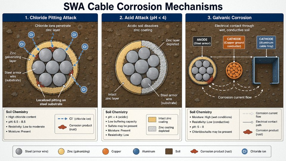
Galvanic corrosion is a third failure mode that gets overlooked in design, particularly where SWA cables terminate into aluminum cable trays or run adjacent to buried copper grounding conductors. Any dissimilar metal contact, combined with a conductive electrolyte (wet soil, contaminated groundwater), sets up a galvanic cell. The steel armor becomes the anode and corrodes faster than it would in isolation.
How SWA Compares to Alternatives
This is where the comparison gets practically useful. Steel tape armored (STA) and double steel tape (DSTA) constructions have larger surface area exposed to soil contact, which generally makes corrosion worse, not better — more steel in contact with the environment. Aluminum wire armored (AWA) cable is a legitimate upgrade for corrosion resistance: aluminum forms a stable passive oxide layer and performs considerably better in chloride-rich or mildly acidic conditions. The tradeoff is reduced tensile strength, which matters in vertical runs or long horizontal pulls. Stainless steel armor exists and is genuinely excellent in aggressive chemical environments, but the cost premium is substantial — expect to pay roughly 2–4× the price of standard galvanized SWA for comparable cross-sections, depending on wire diameter and alloy grade.
Standard galvanized SWA cable can show measurable surface rust within 12–24 months when buried in soils with chloride concentrations above 500 ppm or pH below 4.True
This is consistent with field investigation data and the threshold values referenced in IEC 60502-1 and BS 6346 corrosion performance literature. The zinc sacrificial layer depletes faster than anticipated under these specific electrochemical conditions.
The Outer Sheath Problem
A lot of engineers assume the PVC outer sheath provides a meaningful corrosion barrier. It does — until it doesn’t. Standard Category ST1 and ST2 PVC sheaths are relatively soft and notch-sensitive. During installation, particularly when cables are pulled through rocky backfill or dragged over concrete duct edges, sheath abrasion or micro-cuts are common. Once the sheath is breached, soil moisture reaches the armor directly, and the protection you were counting on is gone.
Adding a PE (polyethylene) oversheath — thicker, harder, more chemically resistant — is the correct engineering response for aggressive environments. PE oversheathed SWA performs substantially better in acid and chloride exposure. But that oversheath adds cost (roughly 8–15% on total cable price, depending on wall thickness and cable diameter) and increases the overall diameter, which feeds back into the bending radius and conduit sizing problems discussed in the previous section. Cathodic protection systems, sometimes specified for critical buried circuits in coastal industrial plants, add further infrastructure cost and require ongoing maintenance. Neither solution is unreasonable — but together they chip away at the “simple, direct-burial, no-fuss” narrative that makes SWA attractive in the first place.
In practice, the engineers who run into the worst corrosion failures are the ones who specified standard SWA based on a desk-level soil survey, then found the as-built ground conditions were nothing like the survey predicted. Soil chemistry varies over short distances. That’s worth keeping in mind before signing off on a 5 km underground distribution run through industrial estuary land.
Higher Material and Total Installed Cost Compared to Alternative Armoring Systems
SWA cable is often specified as a default on projects where “buried power cable” appears in the scope — and that default costs money. The steel wire armor layer is not a trivial addition to the bill of materials. It involves wire rod procurement, drawing down to the required wire diameter, galvanizing (hot-dip or electrolytic), and then a separate planetary stranding pass over the cable core. Each of those steps carries its own scrap rate, energy input, and process time. A plain tape-armored or unarmored XLPE construction skips most of that entirely.
Steel Wire Content as a Share of Total Material Cost
For small conductor sizes — say, 4-core 10mm² or 16mm² — the armor wire is relatively light gauge and its material contribution to total cable cost is modest, usually somewhere in the 4–7% range depending on copper price at the time. But at 185mm² and above, the math shifts. The armor wire diameter increases to maintain the mechanical protection ratio, and the total steel mass per meter climbs enough that the galvanized wire content can represent roughly 8–14% of total cable material cost. That share shrinks when copper prices spike and grows when they fall — so the absolute premium varies, but it rarely disappears.
Aluminum wire armored (AWA) cable uses aluminum alloy wires instead of steel. Aluminum costs more per kilogram than galvanized steel wire, but it weighs about a third as much, so the total armor-layer mass (and therefore cost) is substantially lower for an equivalent cross-section. In practice, AWA cable in the 50–300mm² range typically lands at a 5–12% lower total material cost than equivalent SWA, depending on conductor size and prevailing metal prices. It also eliminates the galvanizing process entirely.
For large conductor sizes (185mm² and above), steel wire armor can represent 8–14% of total SWA cable material cost.True
Steel wire diameter must increase proportionally with cable diameter to maintain mechanical protection performance. At large conductor cross-sections, total armor wire mass per meter rises significantly, and this is consistent with standard IEC 60502-1 armor wire sizing tables and manufacturer bill-of-materials breakdowns.
Comparing Total Installed Cost per Meter: Three Scenarios
Take a realistic example: a 4-core 50mm² run, roughly 500 m, in a general industrial site with competent soil — not highly corrosive, not coastal.
| Scenario | Approx. material cost/m | Installation cost drivers | Relative total installed cost |
|---|---|---|---|
| SWA-XLPE, direct burial | Moderate-high | Trench only, no conduit; gland labor | Baseline |
| Unarmored XLPE in steel conduit | Lower cable cost | Conduit material + installation + pull labor | 15–35% higher total, depending on conduit run length and diameter |
| AWA-XLPE, direct burial | Moderate | Same trench; lighter; faster pull | 5–12% lower than SWA total |
SWA is genuinely cost-competitive in straightforward direct burial without conduit. That is the scenario it was designed for. The moment a project adds conduit — because of surface crossings, road ducts, or congested underground routes — the picture changes. The conduit itself provides mechanical protection, making the steel armor redundant, and the weight penalty of SWA then just adds freight cost and installation labor for no protective benefit.
Hidden Costs That Procurement Managers Often Miss
Termination glands are not trivial. SWA cable requires either A2-type cable glands (for the steel armor) or BW-type glands where a brass backnut clamps onto the armor wires, and both require proper armor earth continuity to be established at every termination — typically via an earth tag or separate earthing clamp back to the panel earth bar. On a small panel with four cables, that is manageable. On a large distribution substation with 40–60 SWA terminations, the gland and earthing hardware alone can add $800–2,500 to the job, and labor time per termination runs noticeably longer than for an equivalent unarmored cable terminated in a standard PG gland.
Freight is another line item that gets absorbed rather than attributed. A drum of 4-core 50mm² SWA at 500 m weighs roughly 20–30% more than AWA equivalent, which can push a shipment over a freight tier threshold or require a larger crane lift at site. Over a single drum it seems minor. Across a large project with dozens of drums, the freight differential is real money.
Surface entry points — where a buried SWA run transitions into an above-grade panel or junction box — often require additional mechanical protection sleeve or conduit stub anyway, which partly negates the armor’s value at precisely that transition. That stub, the gland plate penetration, and the weatherproof fitting are costs that rarely appear in the initial cable schedule estimate.
The total cost of ownership case for SWA is strongest in plain direct burial on straightforward routes. Everywhere else, the alternatives deserve a line-by-line comparison before the specification gets locked.
Electromagnetic Interference and Induced Voltage Problems in AC Single-Core SWA Installations
Most engineers running three-phase underground feeders use three single-core cables rather than one multi-core, particularly at 11 kV and 33 kV where core spacing, thermal management, and jointing access all push that direction. The problem is that single-core SWA cable and AC systems have a genuinely awkward relationship — one that multi-core SWA largely avoids because the magnetic fields from balanced three-phase conductors cancel across the armor layer.
The Physics Behind Induced Armor Voltage
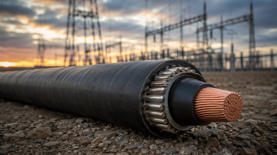
A single-core cable carrying AC current is, in effect, a single-turn primary winding. The steel wire armor surrounding it forms a near-complete closed magnetic circuit. By Faraday’s law, the alternating flux from the conductor induces a longitudinal voltage along that armor. At 50 Hz with typical distribution load currents in the 200–400 A range, induced armor voltages commonly fall between 50 and 120 V/km — the exact figure depends on conductor size, trefoil versus flat formation, phase spacing, and whether the cables are touching or separated.
That range matters enormously in practice. Many national codes, derived from IEC 60949 and IEC 60287, set the permissible touch voltage on accessible metalwork at 25 V. A 300 m run at the lower end of that induction range already puts you close to 40 V. A 600 m run in flat formation can exceed 70 V on the armor surface — a real shock hazard for anyone contacting the cable sheath or termination hardware during normal operation, not just fault conditions.
Induced armor voltages on single-core SWA cables at typical distribution currents can exceed the 25 V IEC touch-voltage safety threshold within a few hundred meters of run length.True
IEC 60287 calculates induced sheath voltages based on current magnitude, frequency, conductor geometry, and cable formation. At 50 Hz with 200–400 A load currents in flat or trefoil formation, voltages of 50–120 V/km are consistent with standard calculations, meaning even runs of 200–500 m can exceed 25 V threshold depending on bonding arrangement.
Circulating Currents and Ampacity Derating
If you bond both ends of the armor to earth — solid bonding, the simplest and most common site practice — you complete the circuit and circulating currents flow continuously through the steel wires. These aren’t trivial. Circulating current losses in solid-bonded single-core SWA installations routinely reduce effective ampacity by 10–25%, depending on formation, spacing, and armor resistance. The steel itself is a moderately resistive path, so that circulating current generates heat directly in the armor layer, wrapped tightly around the insulation.
That heating matters beyond the immediate ampacity derating. Insulation aging follows Arrhenius kinetics — roughly speaking, every 8–10°C sustained rise in XLPE or EPR insulation temperature halves the expected service life. An armor layer running 5–12°C hotter than it should because of circulating current isn’t a catastrophic failure mode, but it’s a slow, invisible one. A cable rated for 30 years in a clean thermal environment may quietly lose a decade of that in a busy substation feeder that was sized without accounting for the circulating-current derating.
What the Standards Actually Say
IEC 60502-2 and BS 6622 are fairly direct on this. Both effectively steer engineers away from steel wire armor for single-core medium-voltage cables. The preferred alternatives are aluminum wire armor (AWA), which has significantly lower magnetic permeability and therefore induces far less voltage, or lead sheath constructions for particularly demanding installations. AWA-induced voltages are typically 60–70% lower than equivalent SWA under the same load conditions, which often keeps you inside the 25 V threshold without special bonding schemes.
Bonding Workarounds and Their Real Costs
Single-point bonding — earthing the armor at one end only, leaving the other end isolated or connected through a surge voltage limiter — eliminates circulating currents entirely. Cross-bonding, used on longer high-voltage circuits, divides the route into minor sections and transposes the armor connections to cancel induced voltages across the whole length. Both methods work. Neither is free.
Single-point bonding requires surge voltage limiters (SVLs) at the unearthed end, screened cable tails, and careful documentation so maintenance crews don’t inadvertently earth the isolated end and create a fault path. Cross-bonding adds link boxes, bonding leads, and transposition joints — easily adding 8–15% to the civil and termination cost of a medium-voltage feeder run, depending on route length and the contractor’s familiarity with the system. On a 2 km urban 11 kV feeder, that overhead is manageable. On a 400 m site distribution circuit that someone specified as single-core SWA out of habit, it’s unnecessary complexity that a multi-core cable or AWA construction would have avoided entirely.
In practice, the electromagnetic limitation of single-core SWA is the one disadvantage that catches projects off guard most often — because it doesn’t show up during installation. It shows up six months later as a thermal investigation, an unexplained ampacity shortfall, or a near-miss when an electrician grabs a termination box.
Termination Difficulty, Specialized Gland Requirements, and Armor Continuity Risks
Anyone who has terminated SWA cable in a tight motor control cabinet on a wet Monday morning knows this is not a quick job. The process has real sequence discipline to it: strip back the PVC outer sheath to the right length, bind the steel wires tightly before cutting so they don’t splay, cut cleanly without the snips skating onto the bedding or inner insulation beneath, fold back the wires over the gland body, thread and torque the locknut to the correct clamping force, verify IP integrity. Get any step wrong and you’re either re-doing it or — worse — leaving a fault you won’t find until a ground fault event puts the protection system to the test.
Compared to terminating an unarmored cable with a standard PG-type or metric cable gland, this sequence genuinely takes 3–5× longer per end. On a straightforward installation — say, 40-odd cables entering a distribution panel — that difference in labor time accumulates fast.
Gland Selection Gets Messy in Practice
The gland type matters more than most installers appreciate. An A2-type gland handles the armor clamping function only; a BW or CW type provides the full combination of armor clamping and an outer sheath seal for IP66/IP68 compliance. Mixing these up — fitting a plain A2 where a CW is specified because the stores only had A2s on the shelf — is far more common than it should be. The result looks correct from the outside but provides no environmental seal at the cable entry point. In outdoor switchgear or underground junction boxes, moisture ingress follows within months, especially in climates with heavy seasonal humidity swings.
Gland sizing compounds this. A nominally “50mm SWA gland” fits a range of actual cable ODs, but armor wire diameter and lay pitch vary between manufacturers, meaning the clamping ring may not grip uniformly across the armor wires. Undersized clamping creates micro-movement; the armor wires work loose over time under vibration or thermal cycling.
The Earth Fault Continuity Problem Is Underappreciated
A loose or incorrectly assembled SWA gland is, in practical terms, a break or high-resistance joint in the earth fault return path. IEC 60364 and BS 7671 both require that the earth fault loop impedance stays low enough to guarantee protective device operation within the required disconnection time — 0.4 s for 230 V final circuits, 5 s for distribution circuits in many configurations. A poorly clamped gland introduces additional resistance into that path; field measurements on poorly installed glands show increases of roughly 0.3–1.5 Ω, depending on contact area, surface oxidation, and whether any anti-corrosion compound was applied.
A loose SWA cable gland can raise earth fault loop impedance enough to prevent an MCB or fuse from operating within required disconnection times under IEC 60364 and BS 7671.True
Earth fault loop impedance limits are set to ensure sufficient fault current flows to operate the protective device within the required time. Additional resistance introduced by a high-impedance armor connection directly reduces fault current, potentially leaving the circuit unprotected during a ground fault.
That failure mode is insidious because it produces no visible symptom until there’s an actual fault. The circuit tests continuity correctly — the armor is still connected — but the impedance under fault current conditions exceeds what the protection device needs to operate quickly. This is one reason UK electrical inspection regimes under BS 7671 treat SWA gland condition as a specific inspection point, not a general one.
Sharp Wire Hazard Is a Real, Documented Risk
Cut steel armor wires are not forgiving. The individual wires are roughly 0.8–1.6 mm diameter depending on cable size, hardened, and freshly cut ends are razor-edged and springy. They splay unpredictably when the binding slips. HSE incident records in the UK and OSHA reports in North America both consistently flag cable armor laceration as a hand and eye injury source — cuts through inadequate gloves, wire ends flicking toward the face during bending.
In markets where SWA cable is well established, most experienced electricians treat cut-resistant gloves (EN 388 level 4 minimum) and safety glasses as non-negotiable for this specific task. In markets where SWA is newly adopted — parts of Southeast Asia, West Africa, some inland regions of South America — that site culture doesn’t exist yet. Installers accustomed to PVC-only cable work come to SWA termination without the right PPE or banding tools, and injuries follow.
The banding tool point is worth being specific about: binding the armor wires with steel banding before cutting isn’t optional procedure, it’s what controls the cut wire ends. Without it, the wires spring outward the moment the last wire is cut. On busy site conditions with multiple trades working in proximity, that’s a hazard extending beyond the cable installer.
Limited Suitability for Dynamic, Flexing, and Tray-Mounted Applications
SWA cable earns its reputation in static buried or fixed installations. Put it somewhere that moves, and the physics turn against you fairly quickly.
Fatigue Failure Under Cyclic Bending
The steel wires in SWA armor are drawn cold, which leaves them with reasonable tensile strength but limited fatigue ductility. Every time the cable bends and straightens — around a sheave, through a drag chain, over a crane pendant loop — those individual wires experience alternating stress at the flex point. Work-hardening progresses with each cycle. The wire doesn’t stretch plastically to relieve the stress; it accumulates micro-cracks until it fractures.
In practice, individual armor wires begin breaking somewhere between 10,000 and 50,000 bend cycles, depending heavily on wire diameter (thinner wires fail faster in tight radii), the actual bend radius relative to cable diameter, and whether the bending is unidirectional or reversing. Reversing flex — like a festoon cable tracking back and forth across a crane bridge — is considerably more damaging than single-direction bending. Once a handful of wires fracture, the broken ends work their way outward through the outer sheath. You end up with protruding wire stubs that are a laceration hazard for any electrician working nearby, and the remaining intact wires now carry a redistributed load, accelerating the failure of their neighbors.
This is precisely why IEC 60227 and IEC 60245 define separate flexible cable constructions with finely stranded conductors, non-metallic or fine-wire braid screens, and flexible insulation systems. SWA is not mentioned in those standards for good reason. Using SWA on crane pendants, cable reels, drag chains, or any continuously traveling cable application is an engineering error, not just a suboptimal choice. The maintenance consequence is predictable: armor wire penetration of the outer sheath, moisture ingress, insulation tracking, and eventually a ground fault or phase-to-phase failure — often on a production-critical piece of equipment.
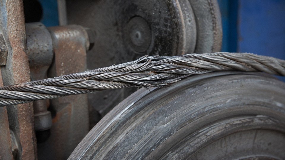
Steel wire armor in SWA cable can experience progressive fatigue wire fractures within 10,000–50,000 bend cycles under continuous dynamic flexing applications such as crane pendants and drag chains.True
Cold-drawn steel wire has limited fatigue ductility. Cyclic bending induces work-hardening and micro-crack propagation at flex points, a failure mode well-documented in cable mechanics literature and the basis for IEC 60227/60245 specifying dedicated flexible constructions for dynamic applications.
Tray Fill and Structural Loading in Large Cable Rack Designs
Dense cable tray installations present a different but equally real problem. SWA cables run heavy — a fully loaded 600 mm-wide tray carrying a mixed population of SWA power cables can easily impose 18–35 kg/m of distributed load, the exact figure depending on conductor cross-section mix and how tightly the tray is filled. Compare that to an equivalent population of LSZH unarmored or aluminum-wire-armored cables, where tray loading typically runs 30–45% lower.
That weight difference has a direct knock-on effect on support structure design. Tray support spans for heavily loaded SWA installations usually need to come down to 0.9–1.2 m centers rather than the 1.5–1.8 m that lighter cable systems allow. In a large petrochemical or power plant with several kilometers of multi-tier cable rack, the additional structural steel — extra cleats, hangers, secondary steelwork — adds up to a non-trivial cost. Structural engineers sometimes don’t catch this until the tray loading calculations come back and the support design has to be revised. That’s a late-stage change nobody wants.
Alternative Constructions for Dynamic and Tray Applications
The right cable for a moving application depends on the specifics of the movement. Here’s a working decision guide:
| Application | Recommended Construction | Key Reason |
|---|---|---|
| Crane pendant, light duty | SY (steel wire braid screened), finely stranded | Flexible, screened, handles moderate cycles |
| Drag chain / cable carrier | PVC or PUR jacketed, unarmored, finely stranded | Purpose-designed for reversing flex per IEC 60227 |
| Festoon system, outdoor | YCW heavy-duty flexible rubber (EPR/CSP) | Oil, UV, ozone resistance; high cycle fatigue life |
| Mine or quarry trailing cable | EPR-insulated trailing cable, textile braid | Designed for ground contact and continuous movement |
| Dense fixed cable tray (process plant) | LSZH with aluminum wire armor | Roughly 30–40% lighter than SWA; adequate mechanical protection for tray routing |
| Tray in fire-risk zones | LSZH unarmored or SWA with fire-rated barrier tape | Depends on fire strategy — check BS 8519 / IEC 60332 |
Jinda’s engineering team regularly fields inquiries where the initial specification calls out SWA simply because it’s familiar, and the actual installation is a cable carrier on an automated overhead crane running 400 cycles per shift. Redirecting those projects to a purpose-built flexible construction isn’t upselling — it’s preventing a failure that would otherwise show up 18 months into commissioning when production is running and nobody wants to pull cables.
Environmental and End-of-Life Disposal Challenges Associated with Steel-Armored Cables
The sustainability conversation around SWA cable has shifted noticeably in the last five or six years. What was once a procurement afterthought — “just spec the armored cable, it’s standard” — is now a line item in EPD submissions, scope 3 carbon inventories, and green building assessments. Engineers who have been specifying SWA for decades are starting to hear questions from clients they weren’t asked before.
Carbon Footprint of Steel Wire Armor: A Gap That Compounds at Scale
Galvanized steel wire production carries a carbon intensity of roughly 2.0–2.5 kg CO₂e per kg of wire, depending on whether the steel mill runs on grid electricity, natural gas, or — in some regions — coal-heavy power. Aluminum wire armor, by comparison, comes in at around 0.35–0.5 kg CO₂e per kg when produced from recycled aluminum stock; primary aluminum is worse, but most armor-grade wire uses a high recycled-content alloy. That’s a 4× to 6× difference in carbon intensity per kilogram of armor material, and it matters more than it sounds once you’re specifying a large cable package.
A typical medium-voltage underground distribution project — say, 10 km of 3-core 95 mm² SWA cable — can carry 8–12 tonnes of steel armor alone. Run the carbon math and the embedded CO₂ contribution from the armor layer alone reaches 16–30 tonnes CO₂e, before you’ve counted conductor, insulation, or sheath. On projects where the client is reporting to BREEAM, UK Net Zero Carbon Buildings Standard, or EU Taxonomy-aligned green finance criteria, those figures end up in the Environmental Product Declaration. EPDs are no longer optional on publicly funded European infrastructure contracts; they’re a submission requirement in several member states.
Galvanized steel wire armor generates approximately 4–6× more CO₂e per kilogram than aluminum wire armor produced from recycled stock.True
Steel wire production via the basic oxygen or electric arc furnace route yields roughly 2.0–2.5 kg CO₂e/kg. Recycled-content aluminum wire armor runs approximately 0.35–0.5 kg CO₂e/kg. The ratio holds across published LCA datasets including those underpinning EN 15804-compliant EPDs for cable products.
End-of-Life Recycling: Where Mixed Materials Destroy Recovery Value
Unarmored copper cable at end of life is relatively clean to process. A licensed cable recycling facility can granulate it, air-separate the polymer from the metal, and recover copper at high purity. SWA cable introduces a problem: the steel armor wire is wrapped concentrically around a polymer bedding layer, which sits over the core assembly. Before any material stream reaches recyclable purity, the armor has to be mechanically separated — either stripped by a specialist granulator or, on older or irregular cable constructions, cut by hand.
In practice, mixed-material SWA cable scrap typically yields 15–25% lower recovery value per tonne compared to equivalent unarmored copper cable at most European licensed recycling facilities. That gap widens if the cable has been in aggressive soil — armor wires corroded to the bedding are harder to separate cleanly, and contaminated polymer fractions reduce value further. The steel recovered isn’t worthless, but it doesn’t command the same premium as the copper stream, and the processing cost to reach purity eats into the margin the recycler would otherwise pass back to the contractor.
For large demolition or decommissioning projects, this isn’t theoretical. Contractors who’ve priced end-of-life recovery into their whole-life cost models sometimes find that SWA cable generates a lower scrap credit than expected — occasionally negative on net, once transport and processing fees are included.
Procurement Policy Pressure: Scope 3 and Green Procurement Criteria
IFC Performance Standard 3, which governs environmental and labor conditions on IFC-financed projects, increasingly requires contractors to account for embedded carbon in materials procurement. Several large EPC contractors operating across Europe, the Gulf, and Southeast Asia have now embedded scope 3 Tier 1 reporting into their supply chain requirements — which means cable manufacturers are being asked for product carbon footprints, not just compliance certificates.
The EU’s green procurement criteria under GPP (Green Public Procurement) don’t yet mandate a specific armor material, but they do reference EPD scores and recyclability ratings for electrical installation products. The trajectory is clear. Projects in the Netherlands, Sweden, and Germany are already seeing tender documents that score cable specifications on embedded carbon as a weighted criterion alongside price.
Jinda’s response to this has been practical rather than cosmetic. The product range includes aluminum wire armored (AWA) constructions to IEC 60502-1 for applications where corrosion and mechanical protection requirements are equivalent to SWA but embedded carbon is a tender criterion. For clients under active BREEAM or LEED assessment, Jinda can provide product-level carbon data and supply documentation formatted for EPD inputs — which saves the project team weeks of back-and-forth during the environmental assessment phase. It’s not a complete solution to every sustainability challenge in cable specification, but it addresses the gap that procurement teams are actually asking about right now.
Frequently Asked Questions About Steel Wire Armored Cable Disadvantages
These are the questions that come up repeatedly — from site engineers mid-project, from procurement managers comparing datasheets, and from contractors who’ve run into trouble on the first fix. Short answers where the question is clear-cut, longer where the reality is genuinely messy.
Can SWA Cable Be Used for Single-Core Medium-Voltage Applications?
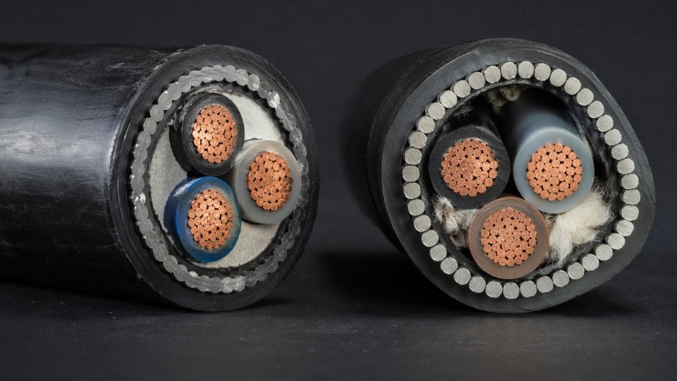
Technically yes, but with a significant caveat that catches people out more than almost any other SWA specification error. On single-core AC cables — think 11 kV or 33 kV feeders — the steel wire armor forms a complete magnetic circuit around a single conductor. The alternating magnetic flux from the conductor induces a circulating voltage in that armor layer. At high load currents, sheath voltages can reach levels that are a genuine shock hazard during maintenance, and the circulating currents themselves represent a continuous energy loss that adds up over a 25-year asset life.
IEC 60502-2 steers engineers away from steel wire armor for single-core MV cables for exactly this reason. The standard alternatives are aluminum wire armor (AWA) — which has higher resistivity, reducing circulating current magnitude — or lead-sheathed designs where single-point bonding or cross-bonding of the sheath is part of the installation design. If you’re specifying single-core feeders above roughly 1 kV, SWA is the wrong armor choice unless the system designer has explicitly addressed sheath bonding and loss calculations.
How Long Does Steel Wire Armor Last When Directly Buried?
In neutral, well-drained soil (pH 6–8, low chloride, IEC 60287-3-2 Class 1 or 2 corrosivity), a properly manufactured SWA cable with an intact HDPE or PVC outer sheath will typically give 25–40 years of service before armor corrosion becomes a structural concern. That range depends heavily on sheath condition — once the outer jacket is breached, service life can drop sharply.
In acidic ground (pH below 5), waterlogged clay, coastal reclaim land, or near industrial effluent, realistic service life falls to somewhere in the 10–15 year range, sometimes less. High chloride concentration — above roughly 500 ppm — accelerates galvanic pitting on the zinc coating faster than most installation specs account for. The armor doesn’t fail catastrophically; it corrodes progressively, losing tensile strength until mechanical protection is effectively gone. By the time that shows up during a dig, the replacement cost is substantial.
SWA cable in neutral soil reliably lasts 25–40 years when the outer sheath remains intactTrue
Sheath integrity is the single largest variable; armor corrosion accelerates dramatically once the protective jacket is breached, regardless of soil classification
Is SWA Cable Safe in Explosive Atmospheres?
The armor construction alone tells you nothing about ATEX or IECEx suitability. What determines zone safety is the entire cable system: the cable’s temperature classification, the gland (which must itself be Ex-certified to IEC 60079-14 and appropriately selected for the zone and gas group), and the method of installation. An SWA cable terminated with a standard brass gland in a Zone 1 area is non-compliant, full stop. EN 60079-1 and IEC 60079-14 both require documented compliance at the system level, not just the cable datasheet. In practice, cables for Ex zones often need additional considerations around surface temperature and potential ignition sources — the armor layer is one small piece of a much larger compliance picture.
What Is the Main Difference Between SWA and AWA Cable?
| Parameter | SWA (Steel Wire Armor) | AWA (Aluminum Wire Armor) |
|---|---|---|
| Weight | Higher — steel adds 20–40% vs. unarmored | Lower — roughly 30–50% lighter than equivalent SWA |
| Corrosion resistance | Moderate — depends on zinc coating quality | Better in most soils and coastal environments |
| Single-core AC use | Problematic — high induced losses | Preferred — lower resistivity limits circulating current |
| Mechanical crush resistance | Higher for equivalent wire gauge | Slightly lower, but adequate for most direct-burial |
| Material cost | Generally lower raw material cost | Usually 10–20% higher, depending on aluminum pricing |
Choose AWA when weight matters (offshore, aerial, long pull distances), when you’re specifying single-core MV cables, or when the installation environment is coastal or moderately aggressive. SWA remains reasonable for multi-core low-voltage underground distribution in neutral ground where cost is the primary driver.
Does Steel Wire Armor Provide Full EMI Shielding?
No — and conflating mechanical armor with electrical shielding is a specification error worth calling out explicitly. SWA provides some attenuation of low-frequency magnetic fields, which is why it can reduce interference pickup on instrumentation cables in certain power environments. But it is not a substitute for a purpose-designed copper tape screen or braided copper shield for signal integrity applications or high-frequency EMI suppression. The steel armor has relatively high magnetic permeability and resistivity compared to copper, and its coverage geometry — individual wires rather than a continuous foil — means it has meaningful gaps at higher frequencies. If you need genuine EMI shielding, specify a copper screen under or over the armor, not instead of it.
How Does Jinda Cable Help Customers Select the Right Armored Cable Construction?
Specification errors on armored cable — wrong armor type, wrong sheath material for the soil chemistry, wrong gland standard for the destination country — are common enough that application engineering support before purchase saves real money. Jinda’s technical team works with engineers and procurement managers to match construction to the actual installation environment: soil corrosivity, dynamic or static routing, single-core or multi-core AC system, and the applicable standard — whether that’s IEC 60502, BS 6346, AS/NZS 5000, or NFC 32-321.
With five production bases across China and supply to more than 50 countries, Jinda carries a broad range of armored constructions including SWA, AWA, STA (steel tape armor), and screened armored designs. Technical consultation is available at no charge, and Jinda’s team can provide compliance documentation, third-party test reports, and sample cables for customer qualification. For projects where getting the armor specification right the first time matters — and it usually does — that’s worth using.