You’ve run a new IP camera installation, the cameras are mounted, the switch is racked, and then someone asks whether the Cat6 you already pulled can actually carry the power — or whether you’re about to run conduit for a separate 24 V feed to every device. Get this wrong and you’re either tearing open a finished ceiling or, worse, pushing a PoE switch past its thermal limits on conductors that weren’t sized for the load, which shows up as intermittent link drops and heat-damaged insulation you won’t diagnose until something fails during a night shift.
Yes, Cat6 cable can carry power through Power over Ethernet (PoE). The same four twisted pairs that carry data also deliver DC voltage from a PoE-capable switch or injector to a powered device. Depending on the PoE standard in use — IEEE 802.3af, 802.3at, or 802.3bt — a single Cat6 run can deliver anywhere from roughly 15 W up to 90 W per port, all within the cable’s rated conductor capacity, provided the run stays within the 100-meter channel limit.
What makes this genuinely worth understanding — rather than just accepting “yes it works” and moving on — is that Cat6’s ability to carry power is not unlimited, not unconditional, and not identical across every cable sold under that name. The conductor gauge, the bundle size, the ambient temperature in the cable tray, and whether you’re using solid or stranded wire all shift the real-world numbers in ways that matter when you’re specifying a 200-drop warehouse build or negotiating a bulk cable order and trying to avoid a costly re-pull two years later.
The Physics of Running DC Power Through Cat6 Twisted-Pair Conductors
Cat6 cable is copper wire. That’s the starting point. The conductors don’t know whether they’re carrying a 10 Gbps data signal or a DC current feeding a PoE access point — they just obey Ohm’s Law and get warm accordingly. Understanding what actually happens inside those conductors when power flows through them is what separates a well-designed PoE installation from one that causes intermittent device resets or, in a worst case, accelerated insulation aging.
Conductor Resistance and What It Costs You in Voltage
Standard Cat6 uses 23 AWG solid copper conductors. Under TIA-568-C.2, the DC loop resistance — meaning the outgoing conductor plus the return conductor measured together — must not exceed 9.38 ohms per 100-meter segment. That figure is a maximum, not a target; a quality cable from a controlled manufacturing line will typically measure somewhere in the 8.5–9.1 ohm range for the full loop, depending on conductor purity and temperature at the time of measurement (resistance rises roughly 0.4% per degree Celsius, which matters in hot plant environments).
Now apply Ohm’s Law to a real scenario. A PoE+ device (IEEE 802.3at, up to 30W) drawing roughly 600 mA at 50V across a 100-meter Cat6 run sees a voltage drop of approximately I × R = 0.6 A × 9.38 Ω ≈ 5.6V — call it 5 to 6 volts depending on actual cable resistance and load. That leaves 44–45V arriving at the powered device. Most PoE-capable equipment is designed to operate down to around 42–44V at the input, so you’re living close to the margin at full run length under full load. Shorten the run to 60 meters or drop to a lighter-loaded device and the problem mostly disappears. Push 90 meters with a high-draw camera or thin-client terminal and you may see brownout-style behavior: the device stays powered but performs erratically, which is one of those faults that takes hours to diagnose on a busy install day.
Heat: The Constraint That Doesn’t Show Up Until It Does
I²R heating is straightforward in isolation and genuinely problematic in bundles. Power dissipated as heat in a single pair equals current squared times the pair’s resistance. At 600 mA through one pair with roughly 4.7 Ω of resistance (half the loop), that’s about 1.3W per pair — not alarming in free air, but cable doesn’t usually run in free air. In a fully loaded conduit or tray carrying 20–40 Cat6 cables simultaneously, mutual heating can elevate individual conductor temperatures by 10–15°C above ambient. In a 40°C plant ceiling space in summer, you’re potentially pushing conductors toward the 60°C insulation rating that UL 444 and IEC 60512 assign to standard Cat6 PVC insulation. Some Cat6 cables carry a 75°C rating (typically with a higher-grade insulation compound), which buys meaningful thermal headroom in bundled runs.
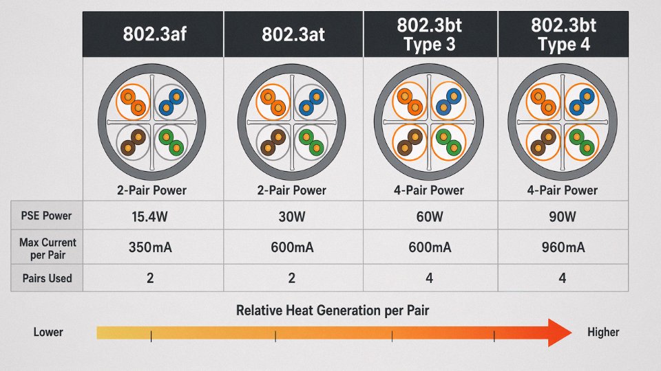
IEEE 802.3bt (PoE++, up to 90W) addresses the heating problem directly by distributing current across all four pairs rather than the two-pair scheme used in 802.3af and 802.3at. Splitting roughly 1.7 A total across four pairs instead of two cuts per-pair current approximately in half, and since heat scales with the square of current, that’s roughly a 75% reduction in per-pair heat generation. It’s a real engineering improvement, not marketing.
Regulatory Standing: Power Cable or Communications Cable?
Cat6 cable is classified as a power cable under NEC.False
Cat6 is classified as communications wiring under NEC Article 800, not as a power cable. It is permitted to carry limited PoE power under the provisions of NEC Article 840 and the relevant IEEE 802.3 standards, but it does not fall under NEC power wiring articles and must not be used as a substitute for branch circuit or general power wiring.
This distinction matters for inspections and insurance. Cat6 lives under NEC Article 800 as communications wiring. PoE is accommodated through Article 840 and the IEEE standards that define its operating envelope. What this means practically: you cannot run Cat6 as a substitute for branch circuit wiring, and an AHJ (Authority Having Jurisdiction) inspecting a facility will look at how your PoE runs are bundled, separated from power conductors, and whether the thermal loading of your cable trays has been considered. It usually hasn’t been, in my experience — especially on retrofit installs where someone adds 30 PoE cameras to a tray that was already half-full of data cabling.
The physics permits PoE over Cat6 within clearly defined limits. Staying inside those limits requires knowing the numbers, not just trusting that the switch will sort it out.
IEEE PoE Standards and How Each One Uses Cat6 Differently
The four major IEEE PoE standards aren’t interchangeable — each places a distinct electrical load on the cable, and understanding those differences is what separates a well-designed installation from one that trips thermal breakers or degrades link margins two years in.
IEEE 802.3af — The Baseline Most Installations Still Run On
Ratified in 2003, 802.3af delivers up to 15.4 W at the PSE (the switch port or midspan injector) and guarantees the powered device receives at least 12.95 W after cable losses. It uses only two of the four pairs, with a maximum current of 350 mA per pair. At that current level, a 100-meter Cat6 run — with its DC loop resistance ceiling of 9.38 Ω per 100 m per TIA-568-C.2 — drops roughly 3.3–3.5 V. Manageable. This tier covers the bulk of installed PoE devices globally: desk IP phones, basic fixed-lens IP cameras, simple access control readers. For most of these applications, even older Cat5e handles the load without issue, which is part of why so many facilities never upgraded their cabling when they moved from analog phones to VoIP.
IEEE 802.3at — Where the Thermal Picture Starts to Matter
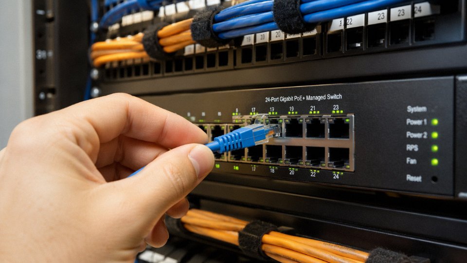
PoE+ (2009) doubles the available power to 30 W at the PSE, 25.5 W at the PD, and raises the current ceiling to 600 mA per pair — still two pairs, same pair selection logic. The higher current means resistive heating is roughly 2.9× higher than 802.3af on the same conductors (power lost to heat scales with I²R). On a properly terminated, unobstructed Cat6 run this is still within safe operating margins. The problem in practice is bundled installations: a 24-port PoE+ switch feeding 24 cables bundled tightly in a conduit creates cumulative thermal loading that can push conductor temperatures above the 60°C threshold where PVC jacket compounds begin to soften. This tier is standard for PTZ cameras, dual-band 802.11ac access points, and thin-client terminals.
IEEE 802.3bt Type 3 — Four-Pair Power Changes the Game
Type 3, also called 4PPoE, arrived with the 802.3bt amendment in 2018. It uses all four pairs simultaneously and can deliver up to 60 W at the PSE, with up to 600 mA per pair. Spreading load across four pairs reduces per-conductor heating compared to pushing 600 mA down two, which is a genuine thermal improvement — but it requires that all four pairs in the cable be electrically sound and properly balanced. A single bad crimp in a Cat5e patch cord, for instance, can force current imbalance across pairs and create a localized hot spot. Cat6 with its tighter manufacturing tolerances handles this more predictably. Typical applications at this tier: digital signage displays, multi-radio Wi-Fi 6 access points, small-form-factor PCs used as kiosk controllers.
IEEE 802.3bt Type 4 — The Upper Limit, and What It Demands of Cable
Type 4 pushes to 90 W at the PSE and 71.3 W at the PD. Current per pair reaches 960 mA — nearly three times the 802.3af limit. At this level, the cable’s resistance and thermal environment are no longer background considerations; they’re central to whether the system works reliably. Voltage drop on a full 100-meter Cat6 run at 960 mA becomes significant enough that some 802.3bt Type 4 deployments intentionally limit runs to 70–80 meters to keep PD voltage within the 42.5–57 V Class 8 window. Applications driving adoption of this tier include LED luminaire networks (especially in retrofit building automation), laptop charging over structured cabling, and building controllers in BAS/BMS installations.
PSE-to-PD Negotiation and Why It Affects Cable Planning
Before power flows, the PSE and PD exchange a classification handshake — originally a resistive signature, now extended via LLDP (Link Layer Discovery Protocol) in 802.3bt. The switch measures the PD’s resistance signature to assign a power class (0 through 8), then decides how much power to allocate. This negotiation matters for cable thermal planning because a switch that doesn’t support LLDP-MED power negotiation may default to over-provisioning — allocating Class 4 or Class 5 power to a device that only needs Class 2. In a bundle of 24 cables, that mismatch can mean the real thermal load in the conduit is meaningfully higher than the device specs suggest. Always confirm switch firmware supports proper 802.3bt classification, especially in 4PPoE retrofits.
Cat6 cable meets the electrical requirements of all four IEEE PoE tiers (802.3af, 802.3at, 802.3bt Type 3, and Type 4) when properly installed.True
Cat6's 23 AWG solid copper conductors and DC loop resistance ceiling of 9.38 Ω/100 m per TIA-568-C.2 keep resistive losses and heat generation within IEEE 802.3bt Type 4 operating margins, provided installation follows bundling, ambient temperature, and termination guidelines.
Comparison Table: PoE Standards and Cat6 Suitability
| Standard | PSE Power | PD Power | Pairs Used | Max Current/Pair | Typical Devices | Cat6 Suitability |
|---|---|---|---|---|---|---|
| 802.3af | 15.4 W | 12.95 W | 2 | 350 mA | IP phones, basic cameras | Excellent |
| 802.3at | 30 W | 25.5 W | 2 | 600 mA | PTZ cameras, Wi-Fi APs, thin clients | Excellent |
| 802.3bt Type 3 | 60 W | 51 W | 4 | 600 mA | Multi-radio APs, digital signage, mini-PCs | Good — verify bundling derating |
| 802.3bt Type 4 | 90 W | 71.3 W | 4 | 960 mA | Laptops, LED luminaires, BAS controllers | Acceptable — limit run length if ambient > 40°C |
Cat5e can support 802.3af and 802.3at without much trouble in typical installations. At 4PPoE loads, Cat5e’s wider resistance variance between manufacturers introduces risk: two cables from different production runs in the same bundle may have meaningfully different thermal profiles. Cat6’s tighter specification reduces that variance. In high-density 802.3bt deployments — a warehouse ceiling grid of 60 luminaires, for instance — that consistency matters more than it might seem on paper.
Heat Rise, Bundle Derating, and the Real Thermal Limits of Cat6 Under PoE Load
A single Cat6 cable powering a 90 W 4PPoE device in free air is not, by itself, a thermal problem. The conductor heats maybe 3–5 °C above ambient under full load — well within the 60 °C insulation rating of standard PVC-jacketed cable. That’s the easy case, and it’s the only case most installers ever think about.
The real risk lives in the tray.
Why Bundled Cables Behave Like Thermal Insulation
Heat dissipation from a cable depends heavily on surface area exposed to moving air. Stack 24 cables in a tight bundle inside a conduit and each cable is mostly surrounded by other hot cables, not air. The outer cables dissipate heat reasonably well; the inner ones can’t. Joule heating accumulates. Depending on conduit fill percentage and ambient temperature, conductor temperatures in fully packed conduit can run 15–25 °C higher than in open tray — sometimes more in poorly ventilated ceiling plenums during summer months.
TIA-568-C.2-1 (2014) and ISO/IEC TR 29125 both address this directly. Their derating guidelines are worth taking seriously: a bundle of 24 cables all carrying PoE++ loads may require reducing maximum run length by roughly 35–40% to keep conductor temperatures within safe limits. That’s not a theoretical edge case — any high-density IP camera or wireless AP deployment with centralized switching will hit exactly this scenario.
Derating Table: Bundle Size, PoE Standard, and Thermal Impact
| Bundle Size | PoE Standard | Recommended Max Run | Est. Temp Rise Above 25 °C Ambient |
|---|---|---|---|
| 1 cable (free air) | PoE++ (802.3bt, 90 W) | ~100 m | 3–6 °C |
| 2–5 cables | PoE++ (802.3bt, 90 W) | 90–95 m | 8–12 °C |
| 6–12 cables | PoE++ (802.3bt, 90 W) | 75–85 m | 12–18 °C |
| 13–24 cables | PoE++ (802.3bt, 90 W) | 60–70 m | 18–28 °C |
| 25+ cables | PoE++ (802.3bt, 90 W) | 50–60 m | 25–35 °C |
| 13–24 cables | PoE+ (802.3at, 30 W) | 80–90 m | 10–16 °C |
| 13–24 cables | PoE (802.3af, 15.4 W) | 95–100 m | 5–9 °C |
Figures assume conduit at 40–60% fill, 25 °C ambient, PVC-jacketed solid-conductor Cat6. Higher ambient temperatures, tighter conduit fill, or plenum installations will shift these ranges toward the worse end.
Conduit Fill: The Variable Nobody Measures
Electricians and low-voltage contractors often treat conduit fill as a code-compliance checkbox rather than a thermal management parameter. In practice, the difference between 40% fill and 80% fill in a 1-inch EMT conduit running 30 cables can mean a 10–15 °C swing in steady-state conductor temperature under full PoE load. Open cable tray with proper spacing performs dramatically better. If you’re designing a new high-density PoE run, open ladder tray is worth the extra bracket cost — not because conduit is wrong, but because it gives you thermal headroom you will eventually need when someone adds more devices later.
Solid vs. Stranded Conductor: It Matters Here
Standard solid 23 AWG Cat6 conductor has DC loop resistance not exceeding 9.38 Ω per 100 m. Stranded-conductor Cat6 — common in patch cords and flexible drop cables — runs slightly higher resistance due to reduced effective cross-section. Over a short patch cord run that difference is irrelevant. Over a 70-meter horizontal run feeding a 60 W powered device in a bundle of 18, that extra resistance means more heat generated per meter. Use solid-conductor Cat6 for all horizontal infrastructure runs in PoE deployments. Reserve stranded for the patch cords where flexibility is actually needed.
Solid-conductor Cat6 generates less heat per meter under PoE load than stranded-conductor Cat6 of the same AWG due to lower effective DC resistance.True
Stranded conductors have a smaller effective cross-sectional area of copper than solid conductors at the same AWG, resulting in slightly higher DC resistance and therefore higher I²R heating per unit length under identical current loads.
When to Specify Cat6A Instead
For any deployment running PoE++ at or near the 100 m channel limit, especially in bundles larger than 12 cables, Cat6A is the pragmatic answer. Its physically larger diameter and improved insulation geometry actually help with heat dissipation — counterintuitively, the bigger cable handles bundled thermal loading better than a tighter-packed Cat6 bundle. The shielded variants (F/UTP or U/FTP Cat6A) dissipate heat more evenly along the jacket. You’ll pay more per meter, but a bundle of 4PPoE devices at 80 m runs on Cat6A is a stable, long-lived installation. The same run on standard Cat6 packed into conduit is a slow failure waiting for a hot August afternoon.
Infrared Scanning as a Commissioning Step
This doesn’t happen nearly often enough. At switch-on commissioning for any high-density PoE patch panel — 24 ports or more, with most ports loaded — run an IR thermal scan across the patch panel face and the cable bundle entry point. Hotspots above roughly 45–50 °C at the jacket surface under normal ambient conditions (25 °C) indicate a bundling or fill problem that should be corrected before the installation is signed off. The same scan, repeated annually as a maintenance check, catches insulation degradation before it becomes intermittent faults or, in a worst case, a smoldering bundle inside a ceiling plenum. A decent FLIR camera takes maybe 15 minutes to sweep a server room or comms room. It’s cheap insurance for an infrastructure that may run for 15 years.
Distance Limitations and Voltage Drop Calculations for PoE Over Cat6
The 100-meter channel limit under TIA-568 gets cited constantly, but it’s a data constraint. Voltage drop can knock out a powered device on a run well under 100 meters, and this catches installers off guard more than almost anything else in structured cabling work.
The Voltage Drop Formula and Why It Matters
The calculation itself is straightforward: V_drop = I × R_loop, where R_loop equals the conductor resistance per unit length, multiplied by two (for the send-and-return path), multiplied by the cable length.
TIA-568-C.2 sets the DC loop resistance ceiling for Cat6 at 9.38 Ω per 100 meters. That works out to roughly 0.0938 Ω per meter of loop — meaning an 80-meter run has a loop resistance in the neighborhood of 7.5 Ω before you account for patch cords.
Walk through a realistic scenario: a PoE++ (IEEE 802.3bt Type 3) device drawing maximum power. The PSE outputs at roughly 50–57 V. At 90 W and 50 V, current on the cable pairs runs to about 1.8 A on two pairs, or nominally around 0.9 A per pair in a four-pair power configuration — but worst-case planning means working with the full current the cable section must carry. Using a 57 V PSE output and a full-load current of approximately 1.57 A across the resistance path of an 80-meter Cat6 run (R_loop ≈ 7.5 Ω), you get a voltage drop on the order of 11–12 V. Delivered voltage lands around 45–46 V — which clears the IEEE 802.3bt Type 3 PD minimum input voltage of 42.5 V, but with less headroom than many engineers expect.
Stretch that same scenario to 95 meters with a marginal cable batch, and you’re looking at borderline or failed operation.
PSE Output, PD Minimums, and Where the Margin Goes
IEEE 802.3bt defines minimum PSE output voltages and minimum PD input voltages precisely because the standard’s authors understood cable losses. Type 3 PSEs must maintain at least 44 V at the MDI under load; Type 4 PSEs have a minimum of 52 V. On the PD side, Type 3 devices must accept input down to 42.5 V and Type 4 down to 50 V. That 1.5–2 V window between PSE floor and PD minimum is narrow — and a poor cable run, a substandard patch cord, or connector oxidation from a humid IDF closet can consume it entirely.
A practical rule from plant and campus deployments alike: budget no more than 80% of the PSE’s rated output when designing runs over 60 meters for 802.3bt. If the PSE is rated at 90 W, plan the infrastructure assuming 72 W is the real ceiling. This absorbs connector losses, patch cord resistance, and cable-to-cable variation within the acceptable manufacturing tolerance band.
Patch Cord Resistance Is Not Trivial
This gets ignored constantly. A 3-meter patch cord using 26 AWG stranded conductors — which is common in pre-terminated patch panels — adds roughly 0.3–0.5 Ω to the loop resistance on its own. That’s small as a fraction of a 100-meter run, but when the horizontal cable is already at 85–90 meters and you have patch cords at both ends, the cumulative loop resistance can approach or exceed the budget limit. Specify 24 AWG stranded for patch cords when deploying 802.3bt at any run over 50 meters. It’s a small cost difference that removes a real failure mode.
Reference Voltage Drop Table
| Run Length | PoE Standard | Approx. Loop R (Ω) | Approx. V_drop (V) | Typical V at PD | Pass/Fail (Type 3) |
|---|---|---|---|---|---|
| 25 m | 802.3af (15.4 W) | ~2.4 | ~1.0 | ~47–48 | Pass |
| 25 m | 802.3bt Type 3 (90 W) | ~2.4 | ~3.8 | ~53–54 | Pass |
| 50 m | 802.3bt Type 3 | ~4.7 | ~7.4 | ~47–49 | Pass (marginal) |
| 75 m | 802.3bt Type 3 | ~7.0 | ~11.0 | ~43–46 | Marginal/Fail risk |
| 100 m | 802.3bt Type 3 | ~9.4 | ~14.8 | ~39–42 | Likely Fail |
V_drop figures assume 1.57 A per conductor path, 57 V PSE output, cable at nominal resistance. Actual values shift with conductor quality, temperature, and connector condition.
Mid-Span Injectors and PoE Extenders
When the run genuinely exceeds what the voltage budget allows, a PoE extender placed around meter 70–75 is the practical fix. The extender receives PoE data and power from the switch, regenerates both, and drives the remaining segment — effectively resetting the voltage drop clock. For lower-power applications (802.3af/at devices, cameras, thin APs), this can extend functional reach to 150–175 meters while maintaining full data throughput. For 802.3bt devices, check the extender’s own power rating carefully; many mid-span extenders are not rated for 90 W pass-through.
A 100-meter Cat6 run always supports full 90W PoE++ deliveryFalse
At 100 meters, loop resistance approaches 9.4 Ω or higher when patch cords are included. Under full 802.3bt Type 3 load, voltage drop typically exceeds 14 V, which can push delivered voltage below the PD minimum input threshold of 42.5 V, causing device startup failure or unstable operation.
Cat6 vs. Cat6A vs. Cat5e for PoE Applications: Which Cable Grade to Specify
The short answer most procurement managers want: Cat6 is your baseline for any new PoE installation, Cat6A earns its cost premium in high-density PoE++ environments, and Cat5e is worth avoiding for new builds even when the price difference looks attractive on a line-item quote.
Here is why that hierarchy exists in practice.
Conductor Gauge and Resistance: Where Cat5e Falls Short
Cat5e uses 24 AWG conductors. Cat6 and Cat6A both use 23 AWG. That single AWG step matters more than the spec sheet implies — 23 AWG solid copper has roughly 8–9% lower DC resistance per unit length compared to 24 AWG, which directly reduces I²R heating and voltage drop under sustained PoE load. TIA-568 sets the same maximum DC loop resistance limit (9.38 Ω per 100 m) for both Cat5e and Cat6, but Cat6’s tighter manufacturing tolerances mean you consistently land at the lower end of that range rather than flirting with the limit. For 4-pair PoE (4PPoE) under IEEE 802.3bt, that consistency is not a nicety — unequal resistance across pairs causes unequal current sharing, which stresses the higher-resistance pairs disproportionately and can cause nuisance PSE shutdowns or, worse, slow thermal degradation you won’t detect until something fails.
Cat5e cable made to spec will technically pass PoE at moderate power levels. In practice, a 90-meter Cat5e run powering a PoE+ access point in a warm ceiling plenum, bundled with a dozen other cables, is a scenario that regularly produces intermittent device resets that are maddening to diagnose.
Why Cat6A Changes the Thermal Equation
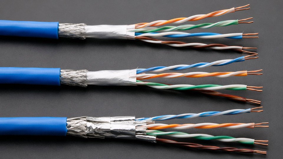
Cat6A’s real advantage for PoE++ is thermal, not electrical. The internal spline separator and larger overall diameter — typically 6–8 mm versus 5–6 mm for standard Cat6 — increase surface area and improve heat dissipation from the cable jacket. ISO/IEC TR 29125 specifically recommends Cat6A for high-power 4PPoE installations precisely because of this geometry. At 60–90 W per port, the cable’s ability to shed heat matters as much as its resistance.
ISO/IEC TR 29125 recommends Cat6A as the preferred cable type for high-power 4-pair PoE (PoE++) installationsTrue
ISO/IEC TR 29125 is the technical report that provides guidance on installing cabling to support PoE, and it identifies Cat6A as the recommended grade for 4PPoE at high power levels due to its superior thermal performance and tighter resistance tolerances.
In a dense ceiling installation with 50+ cables in the same tray, the temperature rise from bundled Cat6A runs measurably lower than equivalent Cat6 — the difference can be 3–6 °C depending on bundle count and ambient conditions, which directly affects safe current carrying capacity.
Shielded vs. Unshielded in PoE Contexts
For most commercial office or warehouse deployments, U/UTP Cat6 is fine. Shielded variants — F/UTP or U/FTP — add cost, require proper grounding at both ends (a requirement that installers sometimes skip, which creates ground loops worse than the EMI you were trying to prevent), and introduce installation complexity that smaller teams routinely get wrong. That said, in environments with genuine EMI sensitivity — hospital imaging suites, laboratory instrumentation areas, industrial floors with VFDs nearby — shielded Cat6 or Cat6A is worth specifying. The key is committing to the full shielding system: shielded patch panels, shielded plugs, continuous ground path. A half-shielded run is often worse than no shielding at all.
Specification Selection Matrix
| Application | Recommended Grade | Shielding | Max Recommended Run |
|---|---|---|---|
| Standard IP camera (802.3af, ≤15.4 W) | Cat6 U/UTP | Unshielded | 90 m |
| PoE+ access point (802.3at, ≤30 W) | Cat6 U/UTP | Unshielded | 85 m |
| PoE++ luminaire or panel controller (802.3bt, ≤60 W) | Cat6A U/UTP | Unshielded | 90 m |
| PoE++ luminaire, high density bundle (802.3bt, ≤90 W) | Cat6A F/UTP | Shielded | 90 m |
| Building automation / BACnet device (low power) | Cat6 U/UTP | Unshielded | 100 m |
| Hospital or lab sensitive environment, any PoE | Cat6A F/UTP | Shielded | 90 m |
Run lengths in the table assume a fully bundled installation in a conduit or cable tray at ambient temperatures up to roughly 30 °C. Drop those figures by 5–10 m if the plenum stays consistently warmer or bundle counts exceed 24 cables.
The Procurement Trade-Off
On a per-meter basis, Cat6A typically costs 30–60% more than standard Cat6, depending on jacket type, shielding, and order volume. For a 200-drop office fit-out where most devices are standard PoE cameras and access points, that premium rarely pencils out. For a facility deploying 802.3bt PoE++ lighting at scale — where you might have 400–600 powered drops in a single building — the thermal and reliability case for Cat6A starts to offset the unit cost difference, especially when you factor in the cost of a service call to diagnose thermally degraded cable in a finished ceiling.
Specify Cat6 as your standard. Upgrade to Cat6A where the power budget, bundle density, or environmental sensitivity actually demands it. Buying Cat6A everywhere because it feels future-proof is a real budget conversation — one worth having with the building owner before you lock in the BOQ.
Installation Best Practices for Cat6 PoE Runs in Commercial and Industrial Buildings
Getting the physics right on paper means nothing if the cable ends up kinked around a sharp conduit edge or bundled so tightly it can’t shed heat. Most PoE failures I’ve seen traced back to installation decisions made during rough-in — decisions that felt fine at the time and only showed up as problems six months later when the building was fully occupied and load density increased.
Bend Radius: Tighter Isn’t Harmless
Cat6 cable requires a minimum bend radius of four times the outer diameter during installation, and eight times for any permanent bend. For a typical Cat6 cable with a 6–7 mm OD, that puts the permanent bend radius at roughly 48–56 mm — call it about 2 inches. That seems generous until you watch an electrician’s helper route cable around a 90-degree bracket with a 15 mm radius because it looked neat.
Tight bends deform the twisted pair geometry. When that geometry changes, pair unbalance increases, which raises both crosstalk and effective resistance. Under PoE load, those effects compound: you’re simultaneously degrading signal integrity and increasing the resistive heating at exactly the point where the cable can’t dissipate heat efficiently because it’s pressed against a surface. Use proper sweep fittings, not sharp elbows, at every direction change.
Conduit Fill: A Code Limit, Not a Suggestion
NEC Chapter 9 caps conduit fill at 40% of the interior cross-sectional area for three or more cables. In PoE-loaded runs, treat this as a hard engineering constraint rather than a compliance checkbox. A conduit filled to 40% with Cat6 cables each carrying IEEE 802.3bt loads is already operating at its thermal limit — the cables in the center of the bundle have almost no airflow. Fill beyond 40% and you’re stacking thermal risk on top of code violation. Specify conduit sizing during design, not during pull.
Cable Ties and Bundle Management
Velcro straps instead of nylon zip ties wherever Cat6 bundles carry PoE loads. This isn’t a preference — overtightening a nylon tie deforms the cable jacket, compresses the pairs, increases crosstalk, and reduces the surface area available for heat dissipation. In practice, even “hand-tight” zip ties applied quickly during a busy rough-in pull can exceed safe compression, especially on thinner-jacketed cables. If you must use zip ties, use the wide-body type and leave them loose enough that the cable bundle can be rotated by hand. A bundle that can’t rotate is too tight.
Termination Quality Matters More Under Load
A poorly seated 110-type punch-down or a keystone jack that wasn’t fully seated before trimming will have elevated contact resistance at that point. Under continuous PoE current draw — especially at 802.3bt levels — that resistance creates a localized hot spot. Over months, oxidation accelerates at elevated temperatures, resistance climbs further, and eventually the connection degrades enough to cause intermittent device resets or outright failure.
Use Cat6-rated tooling, confirm full seating before punching, and don’t reuse patch panels that have been punched more than twice in the same port. Verify every termination with a certified Tier 2 field tester — a Fluke DSX-600 or equivalent — confirming insertion loss, return loss, NEXT, PS-NEXT, and DC resistance balance per TIA-568-C.2. DC resistance unbalance above roughly 3% is a flag worth investigating before the ceiling goes in.
A Tier 2 field tester is required to verify DC resistance balance on PoE-rated Cat6 infrastructureTrue
TIA-568-C.2 and ANSI/TIA-1152-A both specify that DC resistance unbalance measurement requires a Tier 2 (wiremap + channel performance) tester; a basic continuity or Tier 1 tester cannot detect the resistance imbalance conditions that cause PoE power delivery problems.
Jacket Rating and Code Compliance
Cat6 cable used in PoE runs must carry the appropriate listing for its pathway. CM-rated cable is acceptable in general-purpose horizontal runs; CMR (riser) is required in vertical shafts; CMP (plenum) is mandatory in air-handling spaces. Using the wrong rating isn’t just a code violation — it’s a fire safety issue, because PoE-loaded cables generate continuous heat and jacket combustibility matters more than it does in a signal-only installation.
Many international projects, particularly in the EU and the Middle East, require LSZH-jacketed cable regardless of pathway. Specify this at procurement, not during commissioning. Retrofitting LSZH cable after a building inspector flags non-compliant jacket ratings is expensive and entirely avoidable.
Spare Capacity at Commissioning
Leave at least 10% spare capacity in every cable tray and conduit at commissioning. PoE density in commercial buildings tends to grow — wireless access points get upgraded, IP cameras get added, building automation devices proliferate — and a tray that’s full on day one requires a complete re-pull two years later. That 10% buffer is cheap insurance at rough-in and genuinely costly to retrofit.
Non-PoE Power Applications: What Cat6 Cannot and Should Not Be Used For
Cat6 can carry power — but only within a tightly defined envelope. Step outside that envelope and you’re no longer working with a communications cable doing a well-understood job; you’re improvising with infrastructure that was never designed, tested, or listed for what you’re asking it to do.
Cat6 Is a Communications Cable, Not a Power Cable
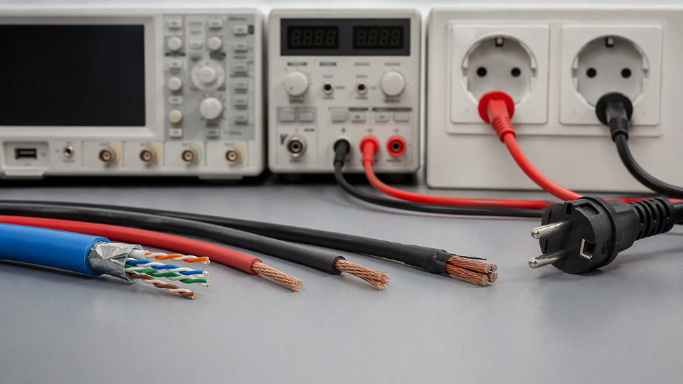
This sounds obvious until you watch someone on a job site run 120V AC through a spare Cat6 run because “it’s already in the wall.” Cat6 is rated under NEC Article 800 as a communications cable. It is not listed, not rated, and not tested as a power cable for AC mains voltage or for high-current DC systems. Full stop. No amount of low-load conditions or “it worked fine for six months” changes that classification — and the classification matters when an insurance adjuster is standing in front of a charred wall cavity.
The insulation on a typical Cat6 conductor is rated to roughly 150V peak as a communications cable. That’s sufficient for PoE DC voltages, which top out around 57V DC under IEEE 802.3bt. It is entirely insufficient for 120V AC (which peaks at about 170V) or 230V AC (which peaks near 325V). The insulation will not fail immediately at overvoltage — it may hold for weeks or months — but dielectric breakdown is cumulative and temperature-dependent, and inside a bundled conduit run the thermal environment only makes it worse.
The DIY Low-Voltage Trap
Twelve-volt DC lighting is where people get comfortable and then get into trouble. The logic goes: “It’s only 12V, Cat6 has copper wire, what’s the problem?” The voltage isn’t the problem. The current is.
A 23 AWG solid copper conductor has a DC resistance of roughly 84–87 ohms per kilometer. Run 12V at even modest load — say, a few LED strips drawing 2–3A total — across a Cat6 pair and you’re pushing current through conductors that have no overcurrent protection sized for that application, no thermal rating for enclosed continuous DC load, and no NEC listing that permits it. Bundled with other cables in a ceiling plenum or J-hook run, the heat has nowhere to go. The insulation softens, adjacent pairs contact each other, and you have the conditions for a smoldering fire that can go undetected for hours inside a wall.
The practical safe limit for 23 AWG in a power context — with proper listing, derating, and protection — is well under 1A continuous in enclosed installations. PoE standards account for this carefully. Random DC lighting loads do not.
Passive PoE and Non-Standard Injectors
“Passive PoE” injectors — the inexpensive ones common in outdoor wireless deployments — place unregulated DC voltages onto Cat6 pairs with no negotiation handshake and no IEEE compliance. Some of these run at 24V or 48V nominal, which sounds fine, but the actual open-circuit voltage from cheap supplies can spike well above that. More importantly, using any non-IEEE power injector immediately voids the UL listing on the cable assembly and typically voids the warranty on any connected equipment. If that run passes through a commercial building, you’ve created a NEC violation and potentially invalidated your building’s electrical insurance coverage — not a hypothetical risk in jurisdictions that require as-built documentation.
Using non-IEEE passive PoE injectors on Cat6 in a commercial building can void the cable's UL listing and invalidate building insurance coverage.True
NEC Article 800 governs communications cable installations. Applying power outside listed and labeled use cases — including non-standard voltage injectors — constitutes a code violation that insurers can and do cite when investigating fire or equipment damage claims.
Where the Safe Boundary Actually Sits
Cat6 may carry power within one clearly defined space: IEEE 802.3 PoE standards, meaning a maximum of 57V DC, maximum roughly 960mA per pair under PoE++ (802.3bt), installed per NEC Article 800 and the applicable PoE installation requirements discussed elsewhere in this guide. Outside that boundary — AC mains, arbitrary DC loads, passive injectors running above IEEE limits, USB power extension hacks — the cable is misapplied and the risk is real. The copper doesn’t know the difference between a safe load and an unsafe one. The listing, the code, and the thermal physics do.
Frequently Asked Questions About Power Delivery on Cat6 Cables
Can Cat6 carry both data and power at the same time?
Yes — and this is precisely the point of PoE. The DC power rides on the copper conductors as a common-mode signal, while Ethernet data travels as high-frequency differential signals in the 1 MHz to 500 MHz range. These two occupy fundamentally different spectral domains and don’t interfere with each other when the installation follows IEEE 802.3 requirements. The magnetics inside a compliant PSE and PD isolate the DC from the data path. In practice, the bigger risk isn’t signal interference — it’s a poorly punched-down jack or a kinked pair causing impedance mismatch that degrades data while also raising resistance on the power path. Both problems trace back to workmanship, not the physics of simultaneous power and data.
How much power can a single Cat6 cable actually deliver to a device?
At the PSE port, IEEE 802.3bt Type 4 (PoE++) sources up to 90W. By the time that power reaches the powered device after resistive losses across 23 AWG conductors at a full 100-meter run, you’re looking at roughly 71–73W available — the exact figure depends on conductor temperature, actual loop resistance, and how many pairs are carrying current. That’s enough for a high-spec multi-radio Wi-Fi 6E access point, a PTZ camera with a heater, or an LED luminaire drawing 60–65W. For shorter runs of 30–40 meters, losses shrink considerably and the delivered wattage comes much closer to the port budget. Don’t assume worst case applies to every drop.
Does running PoE reduce Cat6 data speed?
Not under normal conditions. A properly installed, thermally sound Cat6 channel handles 1 Gbps at full 100 meters and 10 Gbps up to roughly 55 meters whether or not PoE is active. Throughput degradation shows up when heat has softened the insulation and altered pair geometry, when DC resistance has crept up due to a corroded or under-crimped termination, or when a cable has been installed in a tight bundle without derating. The PoE current itself is not the culprit — the thermal and mechanical consequences of a bad installation are.
PoE power does not interfere with Ethernet data signals when IEEE 802.3 standards are correctly followed.True
DC power and high-frequency data signals occupy different spectral domains; IEEE 802.3 PSE/PD magnetics isolate them, and this is well-established in the standard's design.
Is Cat6 meaningfully better than Cat5e for PoE?
Yes, and for 4PPoE it’s essentially non-negotiable. Cat6 specifies 23 AWG solid copper conductors with DC loop resistance not exceeding 9.38 Ω per 100 meters under TIA-568-C.2. Cat5e permits 24 AWG, which has higher resistance per unit length and therefore higher voltage drop and more heat per watt delivered. At 802.3af power levels the difference is manageable. Push into 802.3bt territory — all four pairs energized, up to roughly 600–960 mA per pair depending on type — and the resistance and thermal margins on Cat5e get uncomfortably thin, especially in bundles. Manufacturing consistency also matters; Cat6 tolerances are tighter, so resistance variation across a large installation is smaller and easier to budget for.
Can outdoor-rated Cat6 be used for PoE runs between buildings?
The cable itself will survive the environment. Direct-burial or UV-stabilized outdoor Cat6 is mechanically fine. The real problem is ground potential difference between buildings — even a few volts of potential offset between two grounding systems can drive leakage current through the cable shield or even the data conductors, and in a worst case it damages equipment or creates a shock hazard. Most experienced network engineers recommend fiber between buildings and a small media converter at each end. It adds maybe $80–150 to a run, and it eliminates the ground loop problem entirely. Using outdoor Cat6 for inter-building PoE isn’t impossible if the grounding is carefully bonded and equalized, but that’s a meaningful engineering exercise, not a quick field decision.
Does jacket material — PVC, LSZH, plenum — affect PoE electrical performance?
Electrically, no. The jacket is just a mechanical and environmental barrier; it doesn’t change conductor resistance, pair geometry, or the cable’s ability to deliver current. Where jacket choice matters is fire performance and code compliance. In North American plenum spaces — return-air ceilings, raised floors used as air plenums — NEC requires CMP-rated cable. Many European and Middle Eastern projects specify LSZH because it limits toxic smoke in enclosed or occupied spaces. Running standard PVC jacket in a plenum to save $0.05 per meter is the kind of shortcut that fails a fire inspection or, worse, fails during an actual fire. Specify the jacket for the environment and the applicable code, not for PoE performance.
How do I verify that a Cat6 PoE installation is thermally safe?
Start before installation: check bundle sizes and conduit fill against ISO/IEC TR 29125 derating tables, which will tell you whether a given bundle count requires you to derate the allowable current. After commissioning, run the system under realistic load for a few hours and do an infrared thermal survey of cable bundles, patch panels, and any conduit entry points. Surface temperatures above roughly 45–50°C on a bundle in a 25°C ambient room are a warning sign worth investigating. Pull test reports from your cable supplier confirming DC resistance compliance — not just a spec sheet, but actual production test data. Cables that barely meet resistance limits on paper can drift out of spec over years of thermal cycling, so buying from a manufacturer with documented QC traceability matters more than it might seem at initial procurement.
Sourcing and Specifying Cat6 Cable for PoE Projects: A Procurement Guide
Getting the physics and standards right on paper means nothing if the cable you actually pull through conduit doesn’t meet spec. In large PoE deployments — access control, IP cameras, wireless APs across a multi-story building — the procurement decision is where projects succeed or quietly fall apart six months after handover.
The Minimum Specification Checklist Before You Issue a Purchase Order
Start with conductor material. Full-stop bare copper, 23 AWG solid, for every horizontal run. For patch cords under roughly 5 meters, 24–26 AWG stranded bare copper is acceptable — stranded gives you the flex life at the panel — but the moment someone substitutes copper-clad aluminum (CCA) in either segment, you have a problem.
CCA conductors carry roughly 1.6× the DC resistance of solid copper at the same AWG. Under IEEE 802.3bt PoE++ loads, that resistance difference translates directly into additional voltage drop and heat generation in an already thermally loaded cable bundle. TIA-568-C.2 explicitly prohibits CCA for structured cabling. It is not a grey area.
CCA conductors have approximately 1.6 times the DC resistance of solid copper at equivalent AWG.True
The conductivity of aluminum is roughly 61% that of copper. In CCA wire, the aluminum core dominates the cross-section, producing substantially higher resistance than solid copper of the same gauge — typically 1.5–1.65× depending on cladding thickness and manufacturer.
DC loop resistance for a conforming Cat6 horizontal run must not exceed 9.38 Ω per 100 meters under TIA-568-C.2 and IEC 61156-5. Request the production batch resistance data — not just the datasheet value — before committing volume. A reputable manufacturer can provide per-reel or per-batch test records. If they can’t, that’s diagnostic.
Jacket rating matters and is often underspecified. CM-rated jacket is the baseline for open office cabling. Plenum spaces require CMP (or equivalent UL 910 listing). Riser shafts need CMR minimum. Industrial or outdoor-exposed runs frequently call for LSZH — low-smoke zero-halogen — particularly in tunnels, data centers, or any occupied space where toxic combustion gases are a life-safety concern. Specify this before the order, not after the cable is on site.
Verifying What You’re Actually Getting
Datasheet compliance and actual product compliance are not the same thing. Ask for third-party test reports from ETL, UL, or an accredited European laboratory. RoHS and CE declarations matter for export projects. Then go further: request a sample reel from the production lot you’ll actually receive, not a pre-production sample kept on a shelf for prospective buyers.
Run these tests on the sample yourself, or have an independent lab do it: DC resistance per pair, pair-to-pair resistance unbalance (unbalance above roughly 3–5% of the nominal value suggests inconsistent conductor diameter or drawing defects), insulation resistance (should be well above 500 MΩ per 100 m — anything borderline suggests poor insulation extrusion), and Tier 2 channel performance including NEXT, return loss, and insertion loss. If the cable is destined for 10GBase-T over 55 meters or PoE++ in tight bundles, Tier 2 field testing at installation isn’t optional.
What to Look for in a Factory Audit
The variables that kill PoE performance are usually invisible in the finished product until load conditions expose them. Pair twist lay length is the one most factories cut corners on when production pressure is high — inconsistent lay length wrecks NEXT headroom and creates resistance imbalance between the two conductors of a pair, which matters for PoE phantom-circuit current distribution. Ask auditors to pull real-time production monitoring records, not just finished-goods QC data.
Insulation extrusion consistency determines long-run capacitance balance. Conductor drawing line precision — the machinery that reduces copper rod to 23 AWG wire — determines final diameter tolerance. A factory running five production bases with dedicated drawing, extrusion, twisting, and jacketing lines under a single quality management system has far more control over these variables than a small operation outsourcing any of those steps.
Lead Times, Order Quantities, and Practical Procurement Timelines
Standard Cat6 ships on 305-meter (1,000-ft) reels or 500-meter reels depending on region. For a commercial building project of any real scale — say, 400 drops across four floors — you’re typically looking at 50,000 to 200,000 meters of horizontal cable, sometimes more for campus or multi-building projects. Above roughly 500,000 meters, custom reel lengths and bulk spooling become negotiable.
From a manufacturer carrying raw copper stock and running active production, expect 4–8 weeks for standard Cat6. That range depends heavily on current copper rod pricing (which affects whether manufacturers pre-stock aggressively), order queue, and whether you need custom jacket colors, printing, or LSZH compounding. Build that lead time into your project schedule from the first procurement meeting, not after the conduit is already pulled.
Jinda operates five production bases across China with 470,000 m² of manufacturing capacity and an active export program covering more than 50 countries. The integrated structure — R&D, production, technical support, and after-sales under one roof — means that when a project engineer needs PoE derating calculations, jacket compatibility guidance for a specific building code, or project documentation for customs clearance, that support comes from the same organization that made the cable. For large infrastructure sourcing, that continuity is worth more than it sounds.