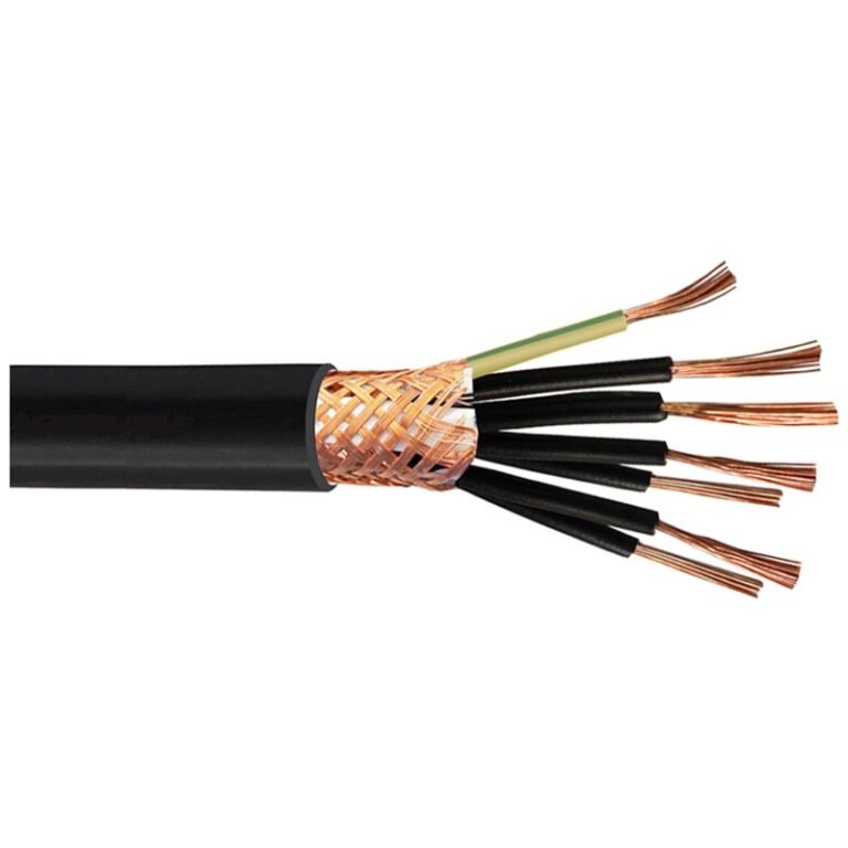
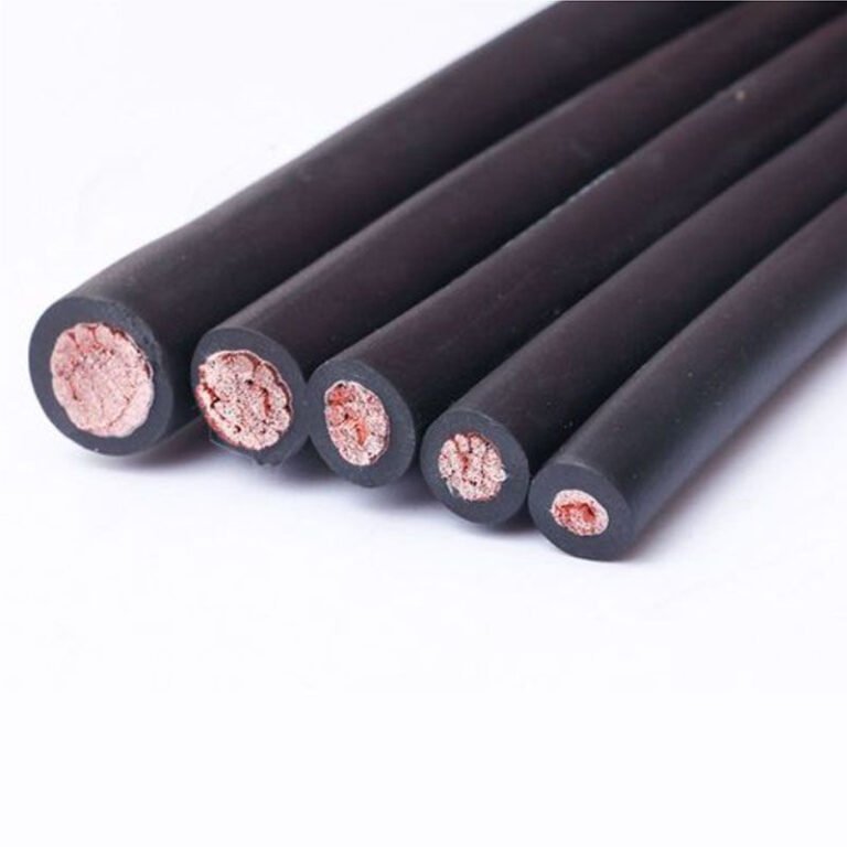
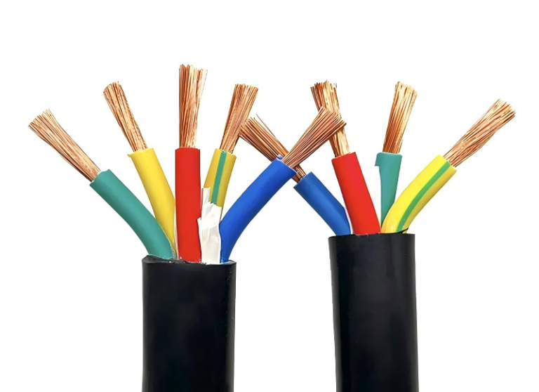
Specify the wrong cable class on a procurement order — say, pulling a 1 kV low-voltage cable into a 10 kV medium-voltage distribution run — and the insulation breaks down, often within months. That failure mode rarely announces itself with a clean trip; it arcs, it causes ground faults, and in a busy plant it can take an entire feeder offline during production. Replacement means excavation or conduit work, emergency procurement at spot-market prices, and downtime that compounds fast. Getting the classification right from the start is the only leverage point that costs nothing.
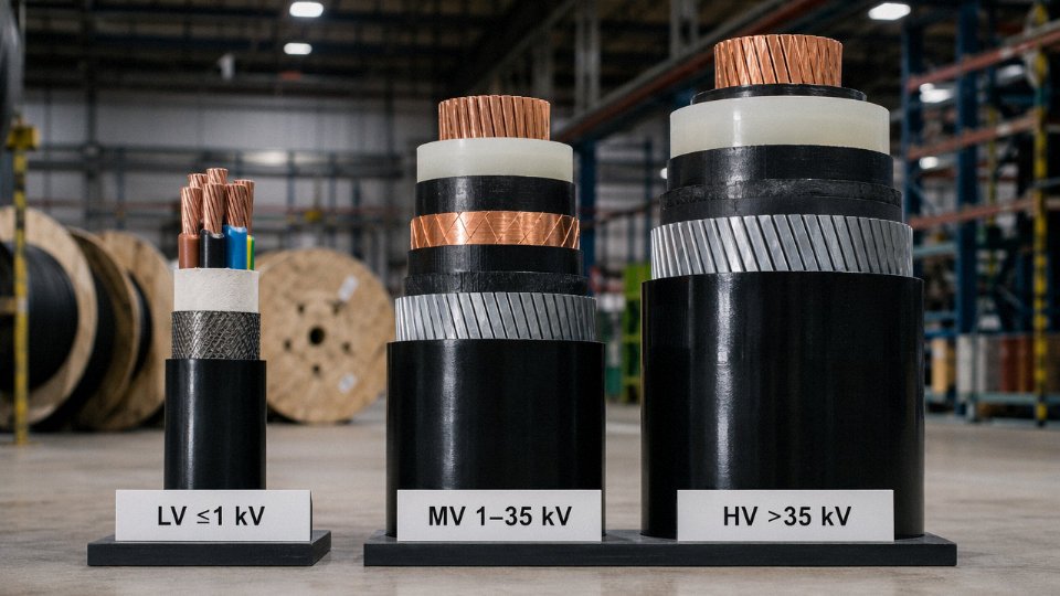
The three types of power cables are low-voltage (up to 1 kV), medium-voltage (1 kV to 35 kV), and high-voltage (above 35 kV, up to 500 kV or beyond for transmission grids). Each class differs in insulation thickness, conductor construction, shielding requirements, and installation standards — and selecting the wrong type for a given voltage level is one of the most costly specification errors in electrical infrastructure work.
What makes the classification genuinely useful — rather than just a textbook sorting exercise — is understanding what physically and electrically separates these three groups, why the global industry has largely converged on XLPE insulation over older PVC designs, and how real procurement and installation decisions play out differently across each tier. The answer is less tidy than most spec sheets suggest.
Low-Voltage Power Cables (Up to 1 kV): Construction, Materials, and Core Applications
Low-voltage cables are, by sheer volume, the workhorse of any electrical infrastructure project. Walk through any factory, apartment block, or solar farm and the vast majority of cable footage you see is LV — rated at or below 1 kV. That doesn’t mean the specification decisions are simple.
Conductor Selection: Copper vs. Aluminum
The conductor is where most procurement arguments start, and for good reason. Copper at roughly 58 MS/m conductivity is the benchmark, and for most industrial machine connections, panel wiring, or anything requiring repeated flexing, it stays the right choice. IEC 60228 Class 1 (solid) suits fixed conduit runs where vibration is negligible; Class 2 stranded is far more common on the plant floor because it tolerates the inevitable bending during pull-through and termination without cracking at the lug.
Aluminum conductors sit around 35 MS/m — about 60% of copper’s conductivity — which means you need a larger cross-section to carry the same current. A 95 mm² aluminum conductor roughly matches a 70 mm² copper in ampacity, give or take, depending on installation method and ambient temperature. The trade-off is weight and cost: aluminum is typically 50–70% lighter and, at current commodity pricing, meaningfully cheaper per meter on large cross-sections. On bulk underground distribution runs of several kilometers, that price gap is real money. The downside is termination discipline — aluminum oxidizes quickly, and a poorly prepared lug joint will fail within a few seasons. Any plant or project specifying aluminum should have a strict protocol for oxide-inhibiting compound and correct torque on every compression terminal.
Insulation Materials
Three materials dominate LV insulation, each suited to different operating conditions.
PVC (polyvinyl chloride) is the legacy choice — cheap, easy to extrude, widely available, and entirely adequate for most fixed indoor wiring. Its ceiling is 70°C continuous conductor temperature. Push harder than that and the insulation softens, migrates away from conductor edges, and eventually cracks. Wherever loads are stable and environments are clean, PVC still makes sense on cost grounds alone.
XLPE (cross-linked polyethylene) handles 90°C continuous and around 250°C under short-circuit for a brief duration. The cross-linking process fundamentally changes the polymer from a thermoplastic to a thermoset, which is why it holds up where PVC doesn’t — higher cyclic loading, outdoor UV exposure, and chemical splash environments. XLPE now accounts for the majority of new LV cable shipments globally, and in practice it’s what you should default to for any industrial or outdoor application where the extra few cents per meter is not the primary constraint.
EPR (ethylene propylene rubber) is the specialist. It stays flexible well below freezing, handles vibration well, and is the standard choice for marine cables, trailing flex on mobile equipment, and offshore installations. It costs more than either PVC or XLPE, so there’s no reason to spec it for a static run in a cable tray.
| Property | PVC | XLPE | EPR |
|---|---|---|---|
| Max continuous temp | 70°C | 90°C | 90°C |
| Short-circuit temp | 160°C | 250°C | 250°C |
| Flexibility | Moderate | Moderate | High |
| Chemical resistance | Moderate | Good | Very good |
| Relative cost | Low | Medium | High |
| Typical use case | Indoor fixed wiring | Industrial/outdoor | Marine, flexible |
Jacket and Armoring Options
Unarmored cables in conduit are fine for most above-ground commercial installations. For direct burial or anywhere mechanical damage is a realistic risk — under roadways, through cable trenches shared with other services, or across a factory yard — SWA (steel wire armored) is the standard answer. The steel wires provide crush resistance and, as a bonus, can serve as a protective earth in some configurations, though you should verify with your installation standard before relying on that.
STA (steel tape armored) uses helical steel tape rather than round wires, which gives better resistance against radial crush in tray installations but less flexibility. It’s common in European cable trays and in applications where the cable routing doesn’t involve significant bends.
LSZH (low-smoke zero-halogen) outer sheaths are non-negotiable in tunnels, metro systems, public buildings, and any confined space where a cable fire would trap people. Standard PVC sheathing, when burning, releases hydrogen chloride gas — corrosive and toxic at very low concentrations. LSZH compounds eliminate that. Specifying LSZH adds maybe 10–20% to sheath cost; failing to specify it in a public-space application and then having an incident is a much larger problem.
Jinda's LV power cables are manufactured in cross-sections from 1.5 mm² up to 630 mm², meeting IEC 60502-1 requirements for voltage class, insulation thickness, and conductor construction.True
IEC 60502-1 is the governing standard for LV and MV cables up to 30 kV; Jinda's stated product range and compliance with this standard is consistent with a manufacturer operating five production bases and serving international markets across 50+ countries.
Where LV Cables Actually Go
The application list is long: residential distribution boards, commercial building risers, motor feeders on light industrial machinery, street and highway lighting circuits, solar PV string wiring between panels and combiner boxes, and increasingly EV charging station feeder runs from the distribution board to the EVSE unit. That last application is worth calling out specifically — EV charger feeders often run at higher continuous load factors than traditional circuits, which means thermal rating matters more than it used to, and XLPE is the sensible default. NFC 32-321 covers French market requirements; BS 6004 governs the UK; IEC 60502-1 is the international benchmark most export projects require. Knowing which standard applies to your project before you issue an RFQ saves time, because the conductor construction tolerances, insulation thickness minimums, and test requirements differ enough to affect lead time if a factory has to switch production parameters.
Medium-Voltage Power Cables (1 kV–35 kV): Shielding Systems, Insulation Grades, and Industrial Use Cases
Once you cross the 1 kV threshold, cable engineering changes in a fundamental way. It’s not just a bigger conductor or thicker insulation — the electric field itself becomes the design problem you’re solving.
Why Electric Field Management Dominates MV Cable Design
At low voltage, the field gradient across the insulation is low enough that minor irregularities at the conductor surface — small voids, surface roughness, eccentricity in the insulation wall — cause no real harm. Push the voltage up to 6 kV, 10 kV, or 33 kV and those same irregularities become sites for partial discharge (PD). Over months and years, PD erodes insulation from the inside out, silently, until the cable fails under load — usually at the worst possible moment.
The fix is the semi-conductive screen system. A thin layer of carbon-loaded semi-conductive compound is extruded directly onto the conductor before the main insulation is applied. This conductor screen smooths out the geometric irregularities of the stranded conductor surface, creating a uniform equipotential surface. A matching semi-conductive insulation screen is then applied over the outside of the insulation, performing the same function in reverse — making the outer insulation boundary equally smooth so the metallic screen above it sees a consistent field. Both layers are typically triple-head co-extruded with the XLPE insulation in the same pass, which matters a great deal: a time gap between extrusion steps allows surface oxidation and contamination that degrades adhesion and creates exactly the kind of interface defects you were trying to avoid.
Layer-by-Layer Construction Logic
Working outward from the center: stranded copper or aluminum conductor → semi-conductive conductor screen (typically 0.5–1 mm) → XLPE or EPR insulation (wall thickness determined by voltage class, typically 3.4 mm at 6/10 kV up to roughly 8–9 mm at 18/30 kV per IEC 60502-2 tables) → semi-conductive insulation screen → copper tape or copper wire metallic screen → polymeric bedding → steel wire armoring (SWA) or aluminum wire armoring (AWA) → outer sheath, usually HDPE or LSZH depending on installation environment.
The metallic screen serves double duty: it carries the capacitive charging current and fault current back to the source, and it defines the outer boundary of the electric field so that nothing outside the cable sees hazardous voltages during normal operation. Screen sizing is not trivial — undersized copper screen will overheat on a single-phase fault before the protection operates, which is a real failure mode in poorly specified mining or offshore installations.
XLPE Versus EPR: It Actually Depends on the Site
XLPE is the dominant choice globally, and for most applications it earns that position. Its dielectric loss factor (tan δ) sits around 0.0004, genuinely low, which reduces heat generation in the insulation itself and allows higher continuous current ratings compared with older PILC cable. Continuous operating temperature reaches 90°C.
EPR behaves differently. Its loss factor is somewhat higher, which costs a little on current capacity, but EPR remains flexible at temperatures down to around −40°C — relevant for outdoor installations in northern climates or refrigerated plant environments where XLPE becomes noticeably stiff and harder to handle without risking insulation cracking during winter installation. EPR also shows better resistance to water treeing, the degradation mechanism caused by moisture ingress under AC stress. For direct-buried cables in consistently wet ground — particularly in coastal or delta regions — EPR’s moisture tolerance is worth the modest current-capacity trade-off.
XLPE-insulated MV cables have lower dielectric losses than EPR-insulated cables of the same voltage ratingTrue
XLPE exhibits a dielectric loss factor (tan δ) of approximately 0.0004, compared with EPR's typical range of 0.002–0.005, resulting in less internal heat generation and higher permissible current-carrying capacity under equivalent installation conditions.
Where MV Cables Actually Go
Wind and solar farm collection networks are among the highest-volume MV applications right now. A typical onshore wind farm strings turbines together at 10 kV–35 kV before stepping up to transmission voltage at the substation; the internal cable network can run to tens of kilometers of MV cable laid in trefoil formation in buried duct banks. Getting the screen earthing arrangement wrong — both ends earthed on long runs without cross-bonding — creates circulating currents in the metallic screen that eat efficiency and generate heat. Single-point or cross-bonded earthing on runs above roughly 300–500 m is standard practice for this reason.
Mining is another demanding environment. Underground mines want flexibility (EPR or fine-stranded conductors help here), resistance to mechanical abuse (double-wire armoring), and often trailing cable configurations that can tolerate repeated flexing. Offshore platforms add the corrosion dimension — AWA is preferred over SWA in marine environments because aluminum armoring doesn’t rust, though the termination and earthing details get more complex.
Urban underground ring-main distribution networks — the looped 11 kV or 33 kV systems that keep city blocks fed even when one cable segment is switched out — demand reliable long service life above almost everything else. A cable that develops PD-induced insulation degradation at year 15 in a congested city duct route is an expensive, disruptive problem. This is where the quality of the triple-extrusion process and the rigor of the factory partial-discharge test (typically performed at 2U₀ per IEC 60502-2) separates adequate product from reliable product.
Standards and the Voltage Upgrade Practice
IEC 60502-2 covers the 1 kV–30 kV range and is the baseline specification most international projects reference. Above 30 kV, IEC 60840 takes over, introducing additional type-test requirements including bending tests, impulse withstand, and long-duration AC voltage tests. VDE 0276 is the German equivalent and is required for projects feeding into German-grid-connected infrastructure. Jinda’s MV cables carry type-test certifications aligned with IEC 60502-2, which satisfies procurement requirements across most utility and industrial project specifications in Europe, Southeast Asia, the Middle East, and beyond.
One practice worth knowing: specifying a 10 kV-rated cable on a 6 kV system is common in industrial plant design where future voltage upgrades are anticipated or where the conservative approach to insulation life is preferred. The thicker insulation wall simply has more margin against partial discharge initiation and moisture ingress. The cost premium is modest relative to the excavation and downtime cost of a premature cable replacement.
High-Voltage Power Cables (Above 35 kV): EHV/UHV Transmission, XLPE vs. PILC, and Grid-Scale Engineering
High-voltage cables are a different discipline from LV and MV work. The physics don’t just scale — they demand an entirely different design philosophy, manufacturing environment, and installation methodology. Getting something wrong at 220 kV doesn’t produce a tripped breaker. It produces a failed joint that takes a transmission corridor offline for weeks.
Sub-Categories Within HV: Three Tiers, Three Sets of Problems
The broad “high-voltage” label actually covers three distinct engineering territories. Conventional HV runs from 35 kV up to 220 kV and serves regional transmission feeders, large industrial substations, and offshore wind collection systems. Extra-high-voltage (EHV) spans 220 kV to 500 kV and carries bulk power across national grids — the backbone circuits that interconnect regional networks. Ultra-high-voltage (UHV) goes above 500 kV, reaching 1,100 kV AC or ±800 kV DC in modern transmission projects, where the economics of transmitting gigawatts over several hundred kilometers justify the engineering complexity.
Manufacturing tolerances tighten at each step. Conductor screen concentricity at 35 kV might be acceptable within ±0.3 mm; at 500 kV that tolerance tightens considerably — in practice, major manufacturers target eccentricity below a few percent of nominal insulation wall thickness, because any geometric irregularity concentrates electric stress and becomes a nucleation point for partial discharge. The cleanroom conditions in a UHV cable extrusion line are closer to semiconductor manufacturing than to a typical cable factory floor.
XLPE vs. PILC: Why the Transition Happened and Where Legacy Systems Still Matter
Paper-insulated lead-covered (PILC) cable was the global standard for HV underground work from roughly the 1920s through the 1980s. It works — there are PILC circuits in European cities that have operated continuously for 50-plus years. The problems with PILC are practical: lead sheaths are heavy (a 132 kV, 630 mm² PILC cable can run 25–35 kg/m depending on design), drum lengths are limited by weight handling, and the oil impregnation system requires vertical installation limits to prevent oil migration under gravity, which means joints every 200–400 m in sloped terrain. If the lead sheath cracks, moisture ingress is immediate and the cable is essentially scrap.
XLPE insulation changed the economics. It handles continuous operating temperatures up to 90°C versus 70°C for mass-impregnated paper, which directly increases ampacity for a given conductor cross-section — typically 10–20% more current capacity for equivalent copper, depending on installation conditions per IEC 60287. XLPE cables are lighter, can be manufactured in longer continuous lengths (400 m to over 1,000 m per drum for 132 kV circuits, subject to handling constraints), and carry no oil migration risk on sloped routes.
XLPE-insulated cables now account for more than 60% of global power cable shipmentsTrue
Industry reports from sources including Mordor Intelligence and Wood Mackenzie consistently place XLPE's share of new power cable installations well above 60% globally, driven by grid modernization, renewable integration, and the phase-out of oil-filled cable systems in most markets.
PILC isn’t obsolete, though. Utility asset managers replacing a section of a 1960s-era 66 kV PILC network often need like-for-like joints to interface with the surviving cable on either side. Specifying XLPE for a 50 m replacement section creates a transition joint — two of them, actually — each of which is a potential failure point and a significant civil cost. In those cases, sourcing PILC is the pragmatic call, even if the material itself is technically inferior.
Construction Details That Separate HV from Everything Below
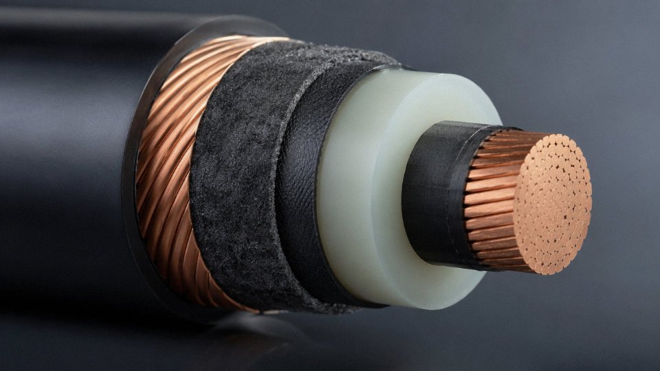
The layered architecture of a modern XLPE HV cable reads almost like a precision instrument. Starting from the center outward: a stranded or Milliken-segmented conductor (Milliken construction reduces AC resistance losses in large conductors above roughly 1,200 mm²), a semi-conductive conductor screen, the XLPE insulation wall (which might be 17–27 mm thick at 132 kV and 27–35 mm at 400 kV, depending on voltage and system earthing), a semi-conductive insulation screen, a metallic screen of copper wires or tape, then a moisture barrier — either a lead alloy sheath or an aluminum laminate — followed by a corrugated aluminum or smooth aluminum sheath for mechanical protection, and finally a high-density polyethylene (HDPE) outer jacket. That HDPE jacket is sometimes specified with a conductive graphite layer for sheath voltage testing continuity after burial.
The semi-conductive layers deserve particular attention. They must be super-smooth — micro-voids or protrusions at the insulation interface create local electric field intensification that initiates partial discharge, which eventually trees through the insulation and causes premature failure. At UHV levels, the compounds used here are specified to surface roughness tolerances that require dedicated compound suppliers and controlled co-extrusion in a triple-head extruder where all three layers go on in a single pass without intermediate surface exposure.
HVDC: A Growing and Technically Distinct Category
High-voltage direct current cables for submarine interconnectors and long overland routes represent the fastest-growing segment within HV. The physics differ from AC: there’s no capacitive charging current, which makes HVDC efficient over distances where AC becomes impractical (roughly beyond 50–80 km submarine or 300–600 km overhead, though the crossover depends on specific system design). Two main cable technologies compete here.
Mass-impregnated non-draining (MIND) cables use a specially formulated high-viscosity paper-oil compound that doesn’t migrate even at maximum operating temperature — this removes the installation slope limitations of older fluid-filled cable and makes MIND viable for deep-water submarine routes where pressures reach 200–300 bar. Extruded HVDC XLPE cables are newer, with commercial service experience building since the mid-2000s; they are lighter and easier to handle on a cable-laying vessel, but the XLPE compound must be formulated to control space charge accumulation under DC fields, which is a different degradation mechanism than AC aging. Manufacturers who produce AC XLPE cable cannot simply run the same compound on a HVDC line — the material qualification process is entirely separate.
Installation Engineering: The Part Procurement Teams Often Underestimate
Specifying the cable correctly is maybe 40% of a successful HV cable project. The rest is installation engineering. Thermal rating calculations per IEC 60287 need soil thermal resistivity surveys along the route — not assumed values, actual measurements, because a 10% error in thermal resistivity can translate to a 5–8% error in cable rating, and that compound over a 10 km route can mean running into thermal bottlenecks at specific geological sections. A cable rated at 630 A in normal soil may only sustain 560 A in a dry sandy section under a road crossing.
Single-core cables — which are standard at transmission voltages — induce voltage on their metallic sheaths. In a trefoil or flat formation, sheath currents circulate unless the sheaths are cross-bonded at regular intervals (typically every 500 m to 1,500 m depending on cable design and acceptable induced voltage limits). Getting the cross-bonding scheme wrong doesn’t necessarily cause immediate failure; it causes continuous circulating current losses that heat the cable and reduce effective ampacity, and you may not notice for years until an unexplained derating becomes necessary.
Field joints at HV are factory-process events, not site craftsmanship. A 400 kV cable joint installation requires a controlled environment tent, humidity monitoring, surface preparation to sub-millimeter tolerances, and technicians who are certified specifically for that joint system. The installation window — meaning the time from opening the cable end to completing the joint — is strictly limited, typically to a few hours depending on the joint type and ambient conditions. Missing that window usually means re-cutting the cable end and starting over, which on a tight tunnel pull schedule is a serious problem.
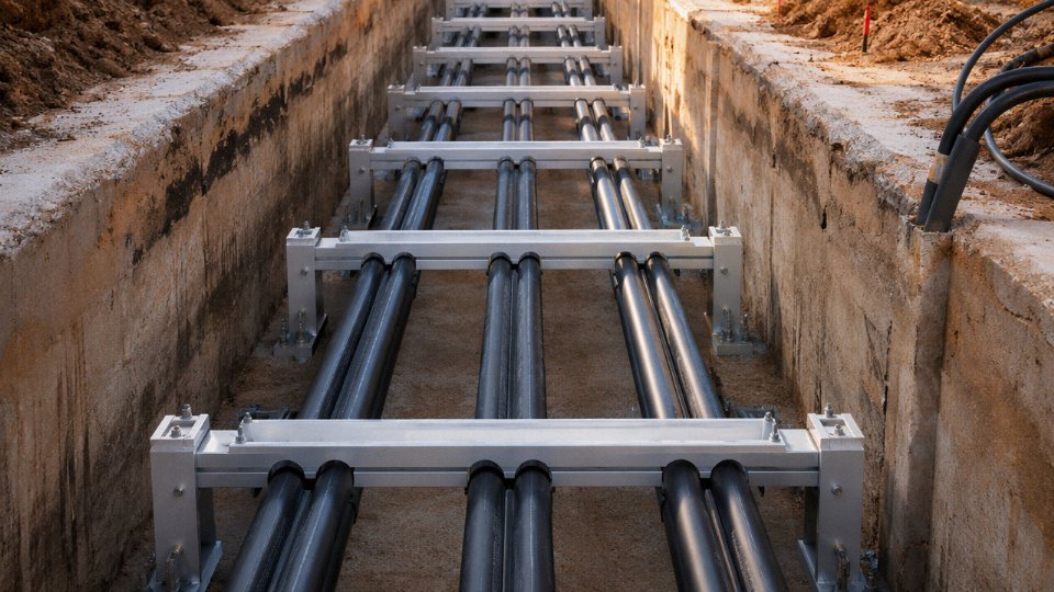
Civil works for HV underground cables — whether direct buried, in concrete ducts, or in purpose-built cable tunnels — add cost that routinely exceeds the cable material cost on urban grid projects. The cable is often not the expensive part. The trench through an urban road junction is.
Side-by-Side Comparison: Selecting the Right Voltage Class for Your Project
Getting the voltage class wrong at the specification stage is one of the more expensive mistakes a project can make — not because the cable itself always fails immediately, but because you end up over-specified on cost or under-specified on safety margins, and neither outcome is cheap to fix once the trench is backfilled.
Reference Comparison Table
| Parameter | Low Voltage (≤1 kV) | Medium Voltage (1–35 kV) | High Voltage (>35 kV) |
|---|---|---|---|
| Typical conductor cross-section | 1.5 mm² – 630 mm² | 35 mm² – 630 mm² | 240 mm² – 2500 mm² |
| Common insulation | PVC (70°C), XLPE (90°C) | XLPE, EPR | XLPE (dry-cured or dry-cured vacuum) |
| Insulation thickness (indicative) | 0.7 mm – 2.8 mm | 3.4 mm – 8.8 mm (Uo/U dependent) | 12 mm – 27 mm+ |
| Armoring options | SWA, AWA, DSTA | SWA, wire armor, lead sheath | Lead sheath, corrugated aluminum, HDPE outer |
| Typical current-carrying capacity | 14 A – ~900 A (depends on install method, grouping) | 100 A – ~700 A | 400 A – 2000+ A (depends heavily on laying depth, thermal resistivity) |
| Key IEC/BS standards | IEC 60502-1, BS 6346 | IEC 60502-2, IEC 60840 (partial) | IEC 60840, IEC 62067 |
| Approximate cost index vs. LV | 1× (baseline) | 3×–8× | 15×–60× |
| Typical project lead time | 2–8 weeks | 6–20 weeks | 6–18 months |
Figures in the table depend on project volume, conductor material (copper vs. aluminum), insulation grade, and whether the order involves specialized fire performance requirements. A large-volume MV order in copper XLPE 11 kV might close toward the lower end of that cost multiplier; a single-project HV cable with submarine screening pushes toward the top.
Load Calculation Fundamentals You Cannot Skip
Peak load current is the starting point, but it rarely tells the full story. Power factor matters: a site running significant motor load at 0.75 pf needs a noticeably larger conductor than the apparent kW figure suggests. Voltage drop limits tighten as you move up the voltage ladder — IEC guidance typically holds LV distribution to ≤5% drop end-to-end, while MV distribution networks are usually designed to ≤3%. Miss that on a 400 V feeder feeding a CNC line 180 meters away and you’ll see nuisance tripping at the drives before you ever hit thermal limits.
Short-circuit withstand is the one parameter junior engineers most consistently undersize. The cable’s conductor cross-section must survive the prospective fault current for the full clearing time of the upstream protective device — not the fuse that might blow in 0.1 s, but the worst-case backup breaker that might take 0.5 s or longer. Ambient temperature derating is equally real: cables installed in poorly ventilated cable trays in a hot press shop in summer run 10–15°C above the assumed 30°C reference, which can knock current capacity down by 10–20% depending on the insulation type.
XLPE insulation is rated for 90°C continuous conductor temperature versus 70°C for standard PVC, providing meaningfully higher current-carrying capacity at the same cross-section.True
This is a well-established IEC 60502-series rating difference, and the capacity advantage typically runs 15–25% depending on cross-section and installation method — enough to matter when conductor cost is a budget constraint.
Environmental and Regulatory Selection Factors
Soil corrosivity in coastal or industrial sites often forces a step up in outer sheath specification — PE instead of PVC, or a bitumen-coated steel wire armor rather than bare. Fire performance requirements deserve serious attention in any cable routed through tunnels, enclosed plant corridors, or multi-story buildings. IEC 60332-3 flame propagation, IEC 60754 halogen emission, and IEC 61034 smoke density are three separate requirements that all need to be explicitly called out in the specification; specifying “fire-resistant cable” without calling the relevant test class leaves enormous room for misinterpretation. In seismic zones, underground MV and HV cables need additional flexibility allowance at joint bays.
A Practical Selection Sequence
Start from confirmed system operating voltage → determine the Uo/U/Um insulation level per IEC 60183 (this is not the same as the nominal system voltage and confusing them is a common error) → select conductor material and size based on load current, voltage drop, and short-circuit withstand → choose insulation type (XLPE for anything where ambient exceeds 40°C or future uprating is possible) → specify armoring based on mechanical exposure and installation method → define outer sheath for chemical, UV, or fire environment → confirm applicable standard and write the procurement specification code in full.
Common Mistakes Worth Naming
Under-sizing for future load growth is probably the most frequent. Adding 20% to today’s calculated load at the design stage costs almost nothing in a new installation but avoids a cable replacement within five years. Specifying PVC insulation on MV cables in hot climates is another one — you see it on projects where the LV spec was copied up without adjusting the insulation class. Omitting LSZH requirements on cables in tunnels or metro infrastructure is a code compliance failure waiting to happen during a fire inspection. And on three-phase LV systems with significant non-linear loads — VFDs, rectifiers, LED drivers — the neutral conductor regularly carries harmonic current well above the phase conductors; specifying a reduced neutral without a harmonic load study is a genuine fire risk.
Material Science Behind Cable Performance: Conductors, Insulation Chemistry, and Sheath Engineering
The voltage-class framework tells you where a cable operates. Material science tells you how long it survives when it gets there. These are different questions, and procurement teams that conflate them end up buying cables that meet the nameplate rating but fail at year eight of a twenty-year infrastructure project.
Copper Conductor Quality: Purity, Drawing, and Surface Finish
Electrolytic tough pitch (ETP) copper at 99.9% Cu minimum is the baseline for any serious power cable. Oxygen-free (OF) copper, typically 99.95% or better, is specified where hydrogen embrittlement in sealed systems is a concern — less common in standard distribution cables, more relevant in certain industrial environments with elevated temperature cycling.
The mechanical story matters as much as purity. Rod drawing down to final conductor diameter, followed by controlled annealing, sets the elongation-at-break (IEC 60228 Class 2 requires ≥ 30% for stranded conductors). Get the annealing temperature or soak time wrong and you produce conductor that’s either brittle — risks strand fracture during installation in cold weather — or too soft, which complicates high-speed stranding and can leave surface micro-tears.
Those surface micro-tears are where MV and HV engineers should pay close attention. Conductor surface roughness is a direct predictor of partial discharge inception voltage. Rough surfaces create localized electric field enhancements at the conductor-screen interface; even small voids or protrusions of 50–100 µm can lower PDIV meaningfully and initiate treeing in the insulation over time. Reputable manufacturers measure conductor surface roughness as part of in-process QC, not as a one-time type-test. Commodity suppliers often skip this entirely.
XLPE Crosslinking Chemistry: Peroxide vs. Silane
Silane (moisture) crosslinking dominates LV cable production because it is economical and compatible with standard extrusion lines. The cable extrudes, grafted silane groups react with atmospheric or bath moisture post-extrusion, and a usable crosslinked structure forms. Crosslink density is moderate and somewhat variable depending on ambient humidity during the cure stage — fine for 0.6/1 kV distribution, acceptable for most building-wiring loads.
Peroxide crosslinking for MV and HV cables is a different operation entirely. It requires a catenary continuous vulcanization (CCV) or vertical continuous vulcanization (VCV) line where conductor, inner semi-con, XLPE insulation, and outer semi-con are co-extruded simultaneously in a triple-head die under strictly controlled conditions — what amounts to a clean-room equivalent for cable manufacturing. The crosslinking reaction occurs inside the heated tube before the cable is quenched. Crosslink density achieved this way is higher and far more uniform, which translates directly to better thermal aging resistance. A well-crosslinked XLPE cable can sustain 90°C continuous conductor temperature over a 30–40 year service life; silane-crosslinked product at the same temperature will degrade faster, particularly under thermal cycling.
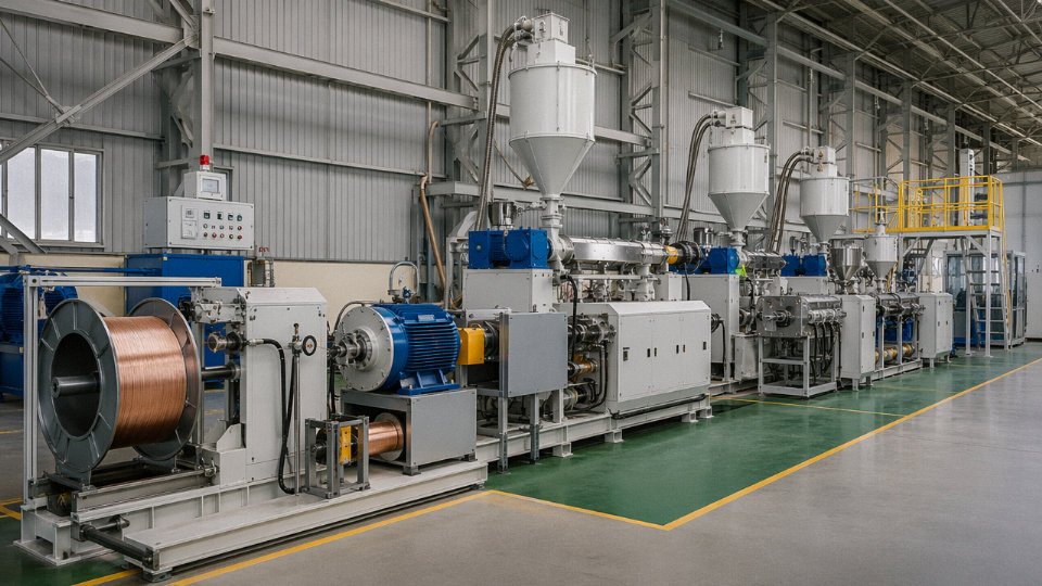
Peroxide-crosslinked XLPE produced on a CCV line provides more uniform crosslink density than silane-crosslinked XLPE, supporting longer thermal aging life in MV and HV applications.True
This reflects established polymer engineering consensus and is documented in IEC 60840 and IEEE 400 series standards; CCV/VCV triple extrusion eliminates the post-extrusion moisture-cure variability inherent to silane systems.
Semi-Conductive Screens: The Interface That Determines Service Life
Carbon-black-loaded polyethylene compounds achieving volume resistivity below 1 Ω·m are the standard for semi-conductive screens. The chemistry is relatively well understood. What separates good screen compound from marginal screen compound is particle dispersion — agglomerated carbon-black clusters create resistivity inhomogeneities that generate local electric field distortions at the insulation interface.
The smoothness of the semi-con/insulation interface is, in practical terms, the single most critical quality variable in medium and high-voltage cable longevity. Protrusions from the inner semi-con into the insulation, or voids at the outer semi-con boundary, are the primary initiation sites for electrical treeing. IEC 60840 specifies protrusion limits for cables above 30 kV; meeting those limits requires tightly controlled compound viscosity, die design, and extrusion speed — not just specifying the right compound on paper.
Steel and Aluminum Armoring: Matching the Mechanical Environment
Galvanized steel wire armor (SWA) offers tensile strength in the 350–500 N/mm² range depending on wire diameter and grade, and handles typical direct-burial mechanical loads well. In acidic or chloride-rich soils — coastal backfill, industrial effluent zones — galvanizing degrades in 10–20 years depending on soil pH and drainage conditions. Steel tape armor (STA) offers crush resistance rather than tensile protection and is generally reserved for grouped duct installations.
Aluminum wire armor (AWA) is the correct choice for single-core AC cables. Steel armor on a single-core AC cable forms a closed magnetic circuit around the conductor, inducing circulating currents that cause measurable hysteresis losses — potentially 5–15% additional losses in heavily loaded circuits. AWA avoids this entirely while still providing adequate tensile strength (roughly 160–220 N/mm²) and better corrosion resistance in mildly aggressive soils. In practice, some installers default to SWA out of habit even on single-core runs; it is a quiet, ongoing waste of energy that rarely gets audited.
Outer Sheath Materials: Fire, UV, and Chemical Resistance
PVC Type ST2 is the default workhorse sheath — cost-effective, easy to process, adequate for most buried or indoor conduit installations. Its weaknesses are well-documented: it emits HCl gas and dense smoke when burning, it softens progressively above roughly 60–70°C ambient (relevant in above-ground desert installations where cable surface temperatures can reach 50–60°C on a hot afternoon before you even account for conductor heating), and UV degradation over several years of direct sun exposure leads to surface cracking.
HDPE sheaths solve the UV and thermal deformation problems — polyethylene in the 0.94–0.96 g/cm³ density range handles direct burial abrasion and maintains mechanical properties at elevated ambient temperatures better than PVC. It does not self-extinguish, which limits its use in enclosed spaces.
LSZH (low-smoke zero-halogen) compounds based on EVA or polyolefin blends are specified whenever personnel egress or sensitive equipment drives the fire-safety requirement. Oxygen index typically runs 30–40% depending on formulation, versus roughly 23–28% for standard PVC. IEC 61034 smoke density and IEC 60754-1 HCl emission tests are the standard qualification hurdles. The tradeoff is real: LSZH sheaths are generally softer and less abrasion-resistant than PVC or HDPE, so installation in rough conduit or rocky direct-burial trenches requires more care. For tropical outdoor above-ground installations, a UV-stabilized LSZH or UV-stabilized HDPE formulation is worth the premium — standard LSZH without UV stabilization will chalk and crack within two to four years in high-UV equatorial environments.
Choosing sheath material is not a box-ticking exercise. It requires knowing the burial medium, ambient temperature range, fire regulation jurisdiction, and whether anyone has thought carefully about what happens to that cable at end-of-life.
International Standards, Testing Protocols, and Certifications That Govern All Three Cable Types
If you’ve spent any time sourcing cables internationally, you already know the standards landscape is messier than any textbook makes it look. IEC dominates globally, but a project in Queensland runs under AS/NZS, a Paris metro contract will reference NFC 32, and anything destined for a US data center or industrial park needs UL listing. Understanding how these frameworks interlock — and where they diverge — is what separates a clean procurement specification from a costly retest or customs hold.
The IEC Standards Hierarchy: An Interlocking System, Not a Menu
IEC 60502 is the workhorse for most projects. Part 1 covers LV cables up to 1 kV; Part 2 steps up to MV cables from 1 kV to 30 kV and introduces Annex B type-test sequences that include bending tests, partial discharge measurement, high-voltage withstand, and thermal cycling across typically 20–40 cycles depending on voltage class. IEC 60840 takes over from 30 kV to 150 kV, and IEC 62067 handles EHV from 150 kV up to 500 kV — at those levels the test regimes are genuinely grueling, with long-duration prequalification tests that can run 12 months or more on installed cable loops.
Underpinning everything is IEC 60228, which defines conductor classes — Class 1 (solid), Class 2 (stranded), Class 5 (flexible), and so on. When a buyer writes “Class 2 conductor” in a spec, they’re referencing IEC 60228 resistance limits per cross-section, which directly links to IEC 60287’s current-rating calculation methodology. These two standards together determine whether a cable will run at the expected load without exceeding its rated temperature — a chain of dependencies that breaks down if you substitute a non-conforming conductor without retesting.
Fire performance lives in IEC 60332 (flame propagation, with Parts 1 through 3 covering single-cable and bunched-cable scenarios), while IEC 60754 governs halogen acid gas emission and IEC 61034 measures smoke density. For any cable installed in tunnels, public buildings, or enclosed industrial spaces, all three should appear in the purchase specification. Specifying only IEC 60332-3 without 60754 and 61034 is a gap that shows up regularly in tenders, and it’s worth catching before award rather than during commissioning.
Regional Variations That Matter for Export Projects
BS 6004, BS 6346, and BS 7846 remain the reference documents for UK and many Commonwealth projects. French-speaking markets — North and West Africa especially — still specify NFC 32-321 and related NFC 32 series cables, which differ in conductor resistance limits and sheath color conventions in ways that catch importers off guard. VDE 0276 governs German and Central European industrial work; the conductor cross-section series and marking requirements differ enough from IEC that a cable marked to IEC 60502 alone may not satisfy a German utility’s incoming inspection. Australian projects under AS/NZS 5000 have their own conductor class definitions and sheath material requirements. North American projects need UL 44 for thermoset-insulated wire or UL 1277 for tray cables — and UL listing is a listed certification on specific constructions, not a blanket approval of a cable family, which confuses some international suppliers.
Type Tests vs. Routine Tests vs. Sample Tests
This distinction matters enormously for high-value contracts. Type tests are performed once per cable design to demonstrate design adequacy — partial discharge at elevated voltage, bending around a mandrel of defined radius, impulse withstand, hot-set elongation on XLPE. They are not repeated on every production run. Routine tests happen on every drum shipped: conductor resistance, voltage withstand (typically 3.5 kV AC for 5 minutes on LV cables, higher for MV), and insulation resistance. Sample tests are periodic audits — tensile strength of the insulation, dimensional checks, degree of crosslinking measured by xylene extraction — done at agreed frequencies during a long-term supply contract.
Buyers who accept a factory-issued type-test report without scrutinizing whether it was conducted on an identical construction to what they’re ordering are taking on real risk. In practice, small changes — a different carbon black grade in the semi-conductive screen, a conductor cross-section not covered by the original report — can invalidate a type test without anyone flagging it.
Third-Party Certification Bodies
KEMA (now operating under DNV) type-test reports carry the most weight for HV and EHV cables in international tenders. A KEMA report documents the complete tested construction in detail, the lab conditions, and the pass/fail results against specific IEC clauses — it’s not a certificate of general compliance, it’s a construction-specific record. SGS, Bureau Veritas, and Intertek are widely used for LV and MV factory audits and shipment inspection. CESI in Italy is respected for HV testing in European utility projects. For any cable above 36 kV, an independent third-party type-test report from one of these bodies should be a non-negotiable tender requirement.
Jinda cables are tested against IEC 60502, IEC 60840, and applicable regional standards with third-party verification available for international project tenders.True
Established manufacturers supplying 50+ export markets routinely maintain IEC-based type-test records and can provide third-party test documentation; buyers should request specific construction-matched reports rather than general compliance statements.
What a Solid Purchase Technical Specification Should Include
Experienced procurement teams know that a vague spec invites low-quality substitutions. At minimum, specify: conductor class per IEC 60228; voltage designation in the Uo/U format (e.g., 0.6/1 kV or 6/10 kV); insulation type and minimum average thickness per the relevant IEC table; whether conductor and insulation screening are required and the resistivity limits for semi-conductive layers; armoring type (wire, tape, SWA, AWA) and material; outer sheath material, minimum thickness, and color coding per the applicable regional standard; drum length tolerances (±5% is typical, but long-route projects sometimes tighten this); which test certificates are required on delivery; and cable marking requirements, which for IEC 60702 and most regional standards include voltage rating, conductor cross-section, standard reference, and manufacturer identification at defined interval spacing along the outer sheath.
Getting this right at specification stage costs almost nothing. Getting it wrong can mean a rejected shipment, a retest cycle running 6–10 weeks for MV constructions, or — worse — an energized cable that fails within the warranty period and takes the procurement team’s credibility down with it.
Installation Best Practices and Long-Term Reliability Across Voltage Classes
Getting the cable specification right is only half the job. A correctly rated, properly manufactured cable can still fail prematurely — sometimes within months — if installation quality is poor. In my experience reviewing cable failure reports from industrial sites, a depressingly large share of early faults trace back not to manufacturing defects but to bend radius violations, undertrained jointers, or ignored thermal backfill requirements.
LV Cable Installation: The Fundamentals That Get Overlooked
Armored LV cables generally require a minimum bending radius of 6–8× the overall cable diameter, depending on whether the armor is steel wire or steel tape and whether the cable is single- or multi-core. Violate that and you risk deforming the insulation cross-section and stressing the armor wires at the bend point — a failure mode that typically shows up years later as a slow insulation resistance decline rather than an immediate trip, which makes it harder to trace.
Pulling tension limits matter just as much. Maximum allowable sidewall pressure in conduit bends is typically in the range of 3,000–5,000 N/m depending on the insulation material and jacket hardness; exceed it during a long horizontal pull with several 90° bends and you can cold-flow the XLPE against the conduit wall without any visible external damage. Use a proper cable grip and tension monitoring during installation — not a guess.
Phasing and color coding per IEC 60446 is non-negotiable on multi-site projects, particularly when local crews are used. Inconsistent color coding across panel sections has caused live re-termination accidents. Cable tray fill ratios also directly affect ampacity: a tray filled beyond roughly 40% of its rated capacity with touching cables needs derating, and that calculation should happen before procurement, not during commissioning.
MV Jointing and Termination: Where Most Field Failures Actually Happen
At medium voltage, the stress cone is not optional geometry — it is a precision electrical component. The conductor screen cutback at a termination creates a point of field concentration that, without the stress cone redistributing that gradient, will initiate partial discharge and eventually tracking failure. Heat-shrink, cold-shrink, and push-on designs each have valid applications, but all of them require a trained and ideally certified jointer who understands why the dimensions on the instruction sheet are not suggestions.
Improper MV cable accessory installation is the single most common cause of MV cable failures in service.True
Multiple utility failure analysis studies and IEC working group reports consistently identify jointing and termination workmanship errors — including incorrect stress cone placement, inadequate cleaning, and wrong screen cutback length — as the dominant field failure mode for MV cables, outpacing manufacturing defects significantly.
A typical industrial site failure scenario: a cable trench crew installs a cold-shrink joint under time pressure without properly cleaning the XLPE surface or maintaining the required 15 mm screen cutback tolerance. The joint passes initial commissioning tests. Within 12–18 months, partial discharge activity at the joint interface grows until a phase-to-earth fault takes out a production line — at a repair and downtime cost that would have paid for ten properly supervised jointing crews.
HV System Integration: Engineering Beyond the Cable Itself
High-voltage cable systems are rarely a straightforward pull-and-terminate job. Factory pre-fabricated joint bays reduce site workmanship variables significantly; specifying pre-fab versus field-assembled joints should be an explicit line item in the project scope, not an afterthought.
Cable sealing ends and GIS cable boxes introduce another transition point where dielectric stress management is critical. DTS (distributed temperature sensing) fiber optic systems, usually embedded in the trench alongside the cable or integrated into the outer sheath, give operators continuous ampacity headroom visibility rather than operating on conservative static ratings. Online partial discharge monitoring adds a second layer: it catches insulation degradation before it becomes a fault, typically giving weeks to months of warning on a HV system where an unplanned outage can have grid-level consequences.
Thermal Management and Ampacity Optimization
Soil thermal resistivity is one of the most under-measured parameters in cable projects. Native soil resistivity varies roughly from 0.5 to 3.0 K·m/W depending on moisture content, soil type, and season — dry sandy soil in summer can be nearly six times worse than saturated clay. Using thermal concrete or selected fine-sand thermal backfill in the cable zone brings resistivity down to a predictable 0.8–1.2 K·m/W range and can recover 10–20% of ampacity compared with uncontrolled native backfill. Burial depth of 0.8–1.2 m is the usual design range; deeper burial reduces surface temperature cycling but slightly increases thermal resistance to ambient.
When multiple cables share a trench, grouping derating applies and compounds quickly — three touching three-core cables in flat formation can require 15–25% derating relative to a single cable, depending on load diversity. Dynamic rating systems that ingest real-time DTS data allow controlled temporary overloading during peak periods, which is increasingly relevant as grid operators try to defer expensive infrastructure upgrades.
Service Life and Predictive Maintenance
XLPE-insulated cables are designed for 30–40 years of service life, but that assumes the installation and operating conditions stay within design parameters. In practice, cables in aggressive soil environments or with repeated overload cycles age faster.
Tan δ (dissipation factor) testing is the most practical early-warning diagnostic for aging XLPE insulation; values trending upward from the baseline established at commissioning indicate moisture ingress or thermal degradation before breakdown voltage is meaningfully affected. VLF (very low frequency, typically 0.1 Hz) withstand testing is increasingly specified for aged MV cables during planned outages — it stresses the insulation enough to reveal weak sections without the energy levels that might cause collateral damage. Maintaining accurate cable route mapping in a GIS system is not glamorous, but third-party excavation damage is statistically one of the top two causes of in-service cable faults globally. A properly documented route record pays for itself the first time a contractor nearly cuts through a 33 kV feeder.
Real-World Project Applications: Renewable Energy, Urban Infrastructure, and Industrial Complexes
The three voltage classes don’t exist in a catalog vacuum — they map directly onto the project types driving the bulk of cable procurement right now. Understanding which cable belongs where, and why, saves specification errors that show up later as warranty disputes, derating surprises, or outright failures in the field.
Utility-Scale Solar PV Plants
A typical ground-mounted solar farm uses cables at three distinct voltage levels simultaneously, which catches some procurement teams off guard the first time they put together a bill of materials.
At the string level, single-core DC cables — usually 4 mm² or 6 mm², rated to 1.8 kV DC per IEC 62930 — run between panel strings and the combiner boxes. These are almost always run above ground on cable trays across the module frames, which means full sun exposure, UV radiation, and in desert installations, ambient temperatures that push 50°C or higher before the conductor self-heating is even factored in. The outer sheath must be genuinely UV- and ozone-resistant, not just labeled as such. Halogen-free LSZH jackets with carbon-black stabilization are the standard call here; cheaper general-purpose PVC will chalk and crack within three to five years in high-UV environments, compromising the insulation beneath.
From the inverter stations outward to the central substation, the plant steps up to MV — typically 10 kV or 35 kV XLPE-insulated three-core cables. These collection circuits carry the aggregated output of dozens of inverters, so any fault on this section takes out a significant block of generation capacity. Specifying the correct cable ampacity with soil thermal resistivity actually measured on site (not assumed from a table) is worth doing properly; undersized MV collection cables are a recurring cause of unexplained efficiency losses in the first operating year.
Onshore and Offshore Wind Farms
Inter-array cables between wind turbines onshore are straightforward MV work — 33 kV XLPE, armored, direct-buried. Offshore is a different problem entirely. The dynamic cable sections connecting floating turbines to the seabed must flex continuously with wave action, which rules out conventional stranded-wire armor and demands finely stranded copper conductors, EPR insulation (which handles wet aging better than XLPE in permanently submerged applications), and in some designs, syntactic foam elements for neutral buoyancy. Getting the conductor stranding wrong on a dynamic offshore section means fatigue cracking of the copper within a few years — replacement costs in an offshore environment are severe enough that the cable specification deserves serious engineering attention, not a lowest-bid commodity purchase.
Export cables — running from the offshore substation back to the onshore grid connection — are high-voltage XLPE, often 132 kV or higher, and are purpose-engineered per project. Lead times of 18–24 months are not unusual.
Urban Underground Distribution Networks
Cities across Europe, the Middle East, and Southeast Asia are steadily replacing overhead MV distribution lines with underground cables, driven by storm resilience requirements and, honestly, public pressure over aesthetics. The typical configuration is an 11 kV or 20 kV ring main unit fed by single-core or three-core XLPE cables, either pulled through pre-installed ducts or direct-buried depending on the street’s congestion level. In dense urban corridors where a single cable trench may carry eight to twelve circuits, compact cross-section cables with reduced overall diameter matter — a difference of 4–5 mm in outer diameter across twelve cables is the difference between fitting the duct bank and having to redesign the civil works.
Mining, Petrochemical, and Steel Mill Applications
Mobile mining equipment — draglines, continuous miners, shuttle cars — needs trailing cables that tolerate constant flexing, dragging across abrasive ground, and exposure to hydraulic oils and mine water. The conductor must be finely stranded for flex life; the sheath, typically SHF1 or SHF2 rubber compound, has to resist both mechanical abuse and hydrocarbon contamination simultaneously. Specifying a standard XLPE armored cable here because it’s cheaper is the kind of decision that results in a mid-shift cable failure and a production stoppage that costs more in a single hour than the cable saving was worth across the whole project.
Steel mill furnace areas introduce sustained high ambient temperatures — 80°C to 120°C in some locations — which pushes cables toward silicone rubber or mica-glass insulation systems rather than standard XLPE. Petrochemical plants add the ATEX/IECEx constraint in classified hazardous areas, where intrinsically safe instrumentation cables with tight capacitance and inductance specifications are mandatory, not optional.
Data Centers and EV Charging Infrastructure
High-density data centers increasingly run 690 V AC distribution rather than 400 V for the server room PDU feeds, because the higher voltage reduces conductor cross-section for the same power delivery — a meaningful saving when you’re routing hundreds of circuits through a congested raised-floor or overhead cable management system. Flexible LSZH power cables dominate here because a fire in a data hall propagating along standard PVC cable runs is a scenario that concentrates minds wonderfully during the design phase.
EV charging parks follow similar logic. A 690 V AC distribution backbone feeding high-power chargers cuts the copper content of the feeder cables noticeably compared to 400 V, and with copper prices sitting where they have been over the past few years, that’s a procurement argument that writes itself.
IEC 62930 specifically governs DC cables for photovoltaic systems, including UV resistance and 1.8 kV DC rating requirementsTrue
IEC 62930:2017 (Electric cables for photovoltaic systems) establishes requirements for PV cables including voltage rating up to 1.8 kV DC, UV resistance, ozone resistance, and heat resistance, directly applicable to string-level wiring in utility-scale solar installations.
Frequently Asked Questions About the Three Types of Power Cables
These questions come up repeatedly in procurement conversations, engineering reviews, and project specification meetings. The answers below are written for people who need to make real decisions, not for casual readers looking for a summary.
Can a control cable be substituted for a power cable, or vice versa?
No — and this is a mistake that causes real damage when it happens. Power cables are engineered to carry load current continuously. Their conductor cross-sections are sized for thermal performance under sustained ampere loading, and their insulation systems are rated for the dielectric stress that comes with operating voltage. Control cables, by contrast, carry low-current signals for instrumentation, protection relays, and switching circuits. They prioritize signal integrity, tight lay of cores, and the flexibility to pack many cores into a compact diameter — typically 0.5 mm² to 2.5 mm² per core, with no meaningful current-carrying intent.
Run load current through a control cable and you get insulation breakdown, likely a fire. Use a power cable where a screened, multicore control cable is needed and you lose signal fidelity, introduce noise, and quite possibly fail a commissioning test. They are not interchangeable under any circumstances.
Why does XLPE dominate modern power cable specifications over PVC?
The thermal ceiling is the starting point: XLPE runs continuously at 90°C versus 70°C for PVC, which translates directly into a higher current-carrying capacity for the same conductor cross-section — or a smaller cross-section for the same load, which matters when you are pulling cables through congested trays. Under short-circuit conditions, XLPE handles up to 250°C; PVC tops out around 160°C. That gap is significant in fault scenarios.
Beyond temperature, XLPE has lower dielectric loss (important at MV and above), better resistance to moisture ingress over time, and no plasticizer chemistry — PVC compounds rely on plasticizers that gradually migrate out of the insulation over years, leading to embrittlement. For any cable with a 30- to 40-year design life, that aging characteristic matters. XLPE is also generally considered a cleaner material from a disposal standpoint, which is increasingly relevant for projects with environmental compliance requirements.
Single-core or multicore — how do I decide?
For three-phase LV systems, three-core or four-core multicore cables are the practical default up to roughly 150–185 mm² per phase. They are cheaper to buy, faster to pull, and easier to terminate. Above that cross-section, the cable gets heavy and stiff enough that single-core runs become easier to handle mechanically, and heat dissipation from tightly bundled large conductors becomes a real derating concern.
At MV and HV, you are almost always using single-core cables, laid in trefoil or flat formation. The reason is partly thermal and partly electrical — induced sheath voltages at these current levels require careful sheath bonding arrangements that are only practical with single-core construction. Specifying a multicore cable at 11 kV or above is unusual and typically only encountered in specialized submarine or mining applications.
What does a cable designation like 3.6/6(7.2) kV actually mean?
The format is Uo/U(Um). Uo is the rated voltage from conductor to earth (or to the metallic screen): 3.6 kV in this example. U is the rated voltage conductor-to-conductor: 6 kV. Um is the highest system voltage the cable is designed to withstand in service: 7.2 kV. Getting this wrong in a purchase specification is a serious error — if your system runs at 6.6 kV nominal with solidly earthed neutral, you need Uo at least equal to the phase-to-earth voltage of that system, and the Um must cover the maximum operating voltage including supply tolerances.
Specifying a cable with insufficient Uo for the system earthing arrangement is one of the most common causes of premature MV cable insulation failure in industrial plants.True
Cables specified with Uo rated for effectively earthed systems but installed on high-impedance or unearthed neutral systems are subjected to full phase-to-phase voltage across the insulation during a single-phase earth fault, accelerating insulation degradation and often causing failure within months rather than decades.
Does Jinda manufacture cables to BS, VDE, NFC, AS/NZS, or other non-IEC standards?
Yes. The IEC series (IEC 60228, IEC 60502, IEC 60840, and others) forms the design baseline for most of Jinda’s product range, but the quality and testing infrastructure accommodates regional variants. BS 6622, BS 7870, VDE 0276, NFC 33-series, AS/NZS 1089 — buyers working in markets that require these should state the applicable standard clearly in their inquiry, along with any local utility or project-specific addenda. Jinda’s technical team will confirm the design parameters, required routine and type tests, and cable marking requirements, and can provide relevant type-test certificates for review before order placement.
What order quantities and lead times should international buyers plan for?
It depends heavily on what you are buying. Standard LV products — think NYY, YJV, or armored multicore in common cross-sections — may be available from stock or producible in 2–4 weeks. Custom MV or HV designs involving non-standard cross-sections, unusual insulation grades, or special sheath compounds that require new tooling or compound qualification typically run 8–16 weeks from order confirmation. For large infrastructure projects, the honest advice is to get into conversation with Jinda’s sales and technical team before the purchase order stage. Last-minute rush requests on specialized MV/HV cable rarely end well for either party.
How should cables be stored and handled before installation?
Drums should stand upright — never flat — on a firm surface, ideally off bare ground. Seal both drum ends to keep moisture out of the cable ends, particularly important for paper-insulated types but good practice for any cable. Keep drums under cover if storage extends beyond a few weeks; prolonged UV exposure degrades PVC sheaths noticeably, and in hot climates it happens faster than most people expect.
When moving drums, roll them in the direction indicated on the drum flank — rolling the wrong way loosens the cable windings and can kink the inner layers. Temperature matters for uncoiling: PVC-insulated cables should not be uncoiled below about 0°C because the sheath becomes brittle and cracks under bending stress. XLPE compounds vary by formulation, but most are workable down to −10°C to −20°C. If you are working a winter installation in a cold climate and the cable drum has been sitting outside overnight, warm it up before pulling. It is a simple precaution that prevents insulation damage that will not show up until years later during a dielectric test.
Why Choose Jinda as Your Global Power Cable Supply Partner
Reaching this point in a cable specification project usually means you’ve already done the hard work — voltage class confirmed, insulation chemistry selected, standards locked down. What remains is finding a manufacturer who can actually deliver what the data sheet promises, on time, in volume, with paperwork that survives a port inspection or a tender review board. That’s where manufacturing depth separates real suppliers from trading intermediaries.
Manufacturing Scale That Covers the Entire Project Schedule
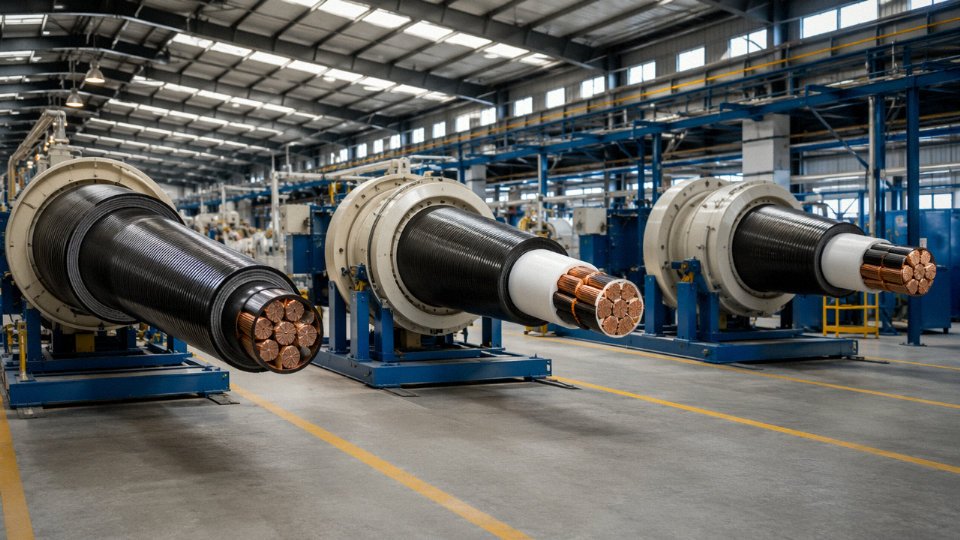
Jinda operates five production bases across China, collectively covering roughly 470,000 m² of floor space — not warehouse, actual production floor. That distinction matters when you’re sourcing a complete project cable schedule rather than a single line item. The facilities include dedicated CCV (catenary continuous vulcanization) lines for MV and HV XLPE cables, where precise temperature and cooling-zone control directly determines insulation quality and long-term dielectric performance. Automated LV extrusion lines handle the high-volume commodity end of a project — the 2.5 mm² and 6 mm² runs that make up most of the unit count but still need dimensional consistency to pass drum-by-drum routine testing. Armoring and sheathing facilities process conductor cross-sections from 1.5 mm² up to 2,500 mm², which covers everything from final-sub-circuit wiring through main HV feeders in a single purchase order.
Single-source supply for a complete cable schedule isn’t just a convenience. It eliminates the coordination risk that comes from splitting a project between three or four vendors with different manufacturing tolerances, different drum-length standards, and different shipping timelines.
Quality Systems and Third-Party Test Documentation
Jinda operates under ISO 9001 quality management and ISO 14001 environmental management certification. Product certifications span IEC, BS, and applicable regional standards across multiple voltage classes. For procurement teams preparing tender submissions, type-test reports from accredited third-party laboratories are available for all three voltage categories — LV, MV, and HV. That’s not a minor point: some manufacturers can produce an IEC certificate but can’t provide the underlying type-test report with full tabulated results. Tender review boards and independent engineers notice the difference.
Jinda provides third-party type-test reports for LV, MV, and HV cable products to support customer tender documentation.True
Third-party type testing by accredited laboratories is a verifiable, auditable quality indicator; Jinda's stated capability to provide these reports for all three voltage classes is a concrete and checkable commitment, not a vague quality claim.
Export Experience and Logistics Practicality
Thirty-seven years of manufacturing since 1987, with active supply into 50-plus countries across Asia, the Middle East, Africa, Europe, and the Americas. The team handles letter-of-credit transactions routinely — not as an exception requiring escalation. Country-specific certification requirements like SONCAP for Nigeria, COI for certain Gulf projects, and HALAL documentation where required are processed as standard workflow, not as surprises that delay shipment by six weeks. Shipments go out as full container loads or groupage depending on project phasing, with professional cable drum packing that accounts for the handling conditions between the factory gate and a remote site laydown area. Anyone who’s received a drum with a collapsed flange at a site in West Africa in August understands why that last point is worth asking about specifically.
Technical Support Before, During, and After Delivery
The technical sales team reviews project cable schedules, identifies specification conflicts before they become shop orders, and prepares compliant submittals. Factory visits are available for key account customers. After delivery, batch traceability means a specific drum can be traced back to its production record, test results, and raw material lot — useful when a contractor questions a measurement discrepancy on site.
How to Start a Project Inquiry
Provide system voltage, required cable standards, conductor cross-sections and lengths, installation environment (direct burial, duct, tray, submersible), delivery port, and target delivery date. Standard product inquiries receive a detailed technical and commercial proposal within 48 hours. Custom specifications — unusual conductor constructions, non-standard armor combinations, special sheath compounds — are quoted within five working days. That timeline is a commitment, not an estimate.