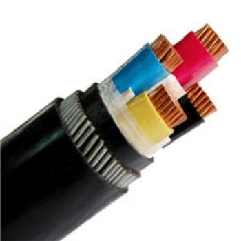
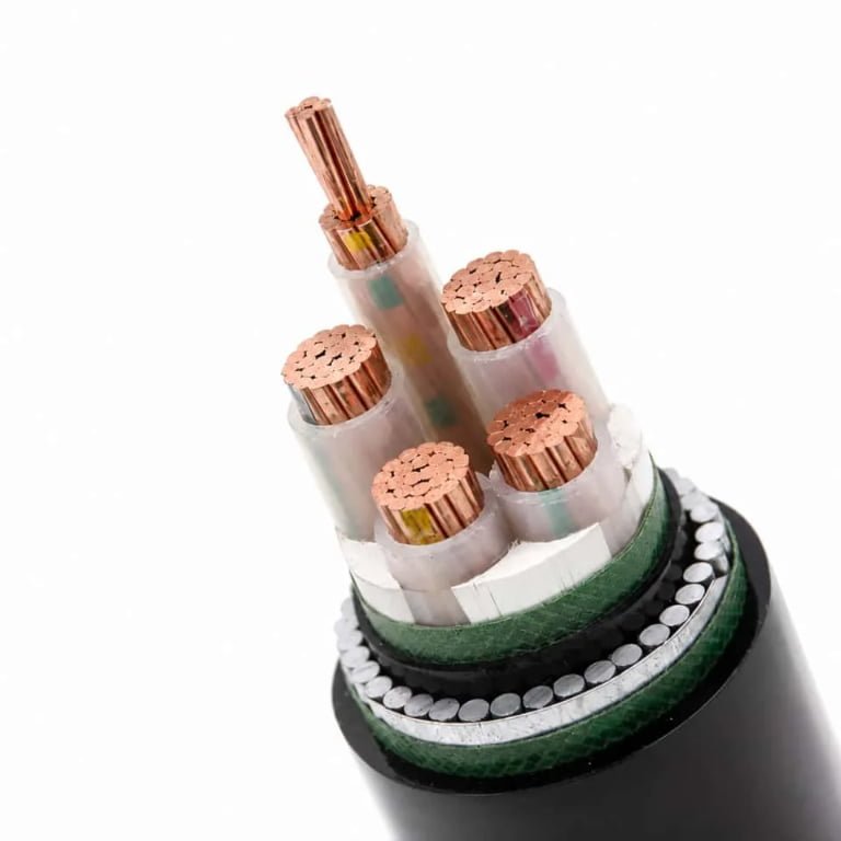
Undersized power cords fail quietly — and that’s exactly what makes them expensive. A cord rated for 10 A feeding a 14 A load doesn’t trip a breaker immediately; it heats up, degrades the insulation over weeks or months, and eventually causes either a nuisance shutdown at the worst possible moment or, in a poorly ventilated enclosure, something worse. On the procurement side, the temptation to standardize on the cheapest 18 AWG cord across an entire facility is understandable — until you’re tracing an intermittent fault in a production line at 2 a.m. and realize the cord to the control panel is running hot to the touch.
Yes, wattage matters for a power cord. The cord’s AWG gauge, insulation rating, and connector spec must all be matched to the connected load — both its steady-state draw and any startup surge. A mismatch doesn’t just risk tripping a breaker; it causes resistive heating, accelerated insulation breakdown, voltage drop that starves sensitive equipment, and in the worst cases, fire. Choosing the right cord means checking the load’s actual wattage, dividing by the supply voltage to get amperage, then selecting a cord rated comfortably above that figure.
What most engineers don’t fully account for, though, is that the wattage rating stamped on a cord or printed in a catalog is not a single fixed number — it’s a ceiling that shifts depending on cord length, ambient temperature, whether the cord is bundled with others, and which connector is terminating it. A 10-meter run behaves very differently from a 1.5-meter patch cord, even if both carry the same label. That gap between the rated spec and the real-world derating is where most procurement mistakes live.
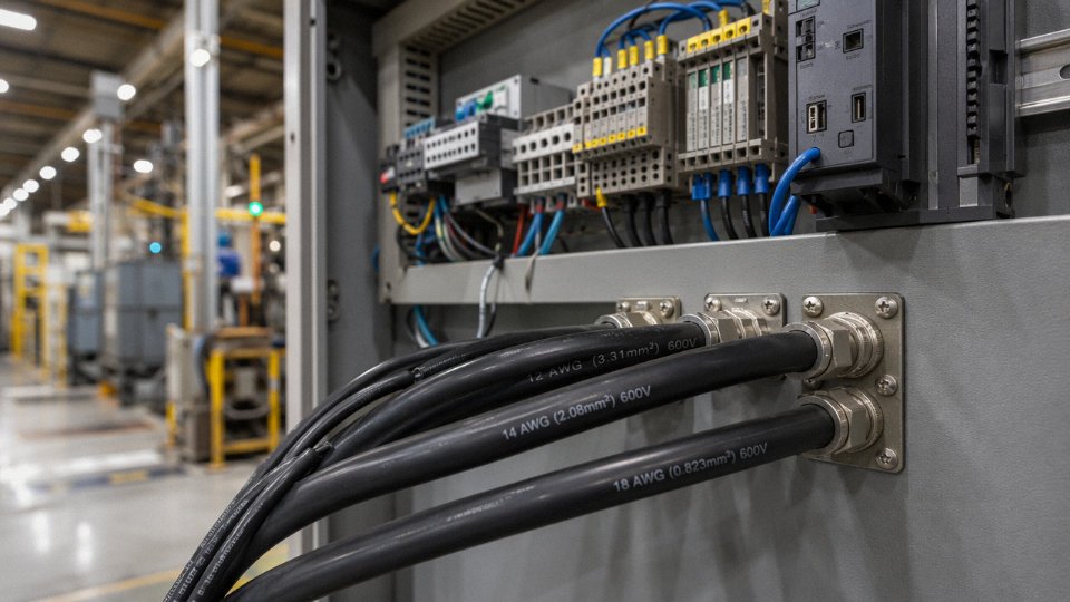
How Wattage, Amperage, and Voltage Interact Inside a Power Cord
The wattage rating stamped on a power cord isn’t a standalone number — it’s the product of two other variables, and if you only look at the watts, you’re already working with incomplete information.
Current Is the Real Stressor, Not Watts
Start with the physics. When current flows through a conductor, the conductor resists it, and that resistance converts electrical energy into heat. The relationship is Joule’s Law: heat generated is proportional to I² × R, where I is current in amperes and R is the conductor’s resistance in ohms. Notice the square. Double the current, and you get four times the heat. This is why amperage — not wattage — is the actual stress variable inside the wire. The conductor doesn’t “know” what the load is doing; it only experiences the electrons being pushed through it.
A 10-meter run of 18 AWG copper cord adds roughly 0.33 Ω of resistance. At moderate loads that’s manageable. Push 12–13 A through that same cord continuously and the I²R heating becomes significant: temperature rise in the insulation, potential degradation over months, and in a worst case, a fire in a cord bundle where heat can’t dissipate. Copper’s resistivity is approximately 1.68 × 10⁻⁸ Ω·m — it’s a good conductor, but it’s not perfect, and length always matters.
The Volts × Amps Formula in Practice
Wattage is simply volts multiplied by amps (for resistive DC or unity power factor AC loads). That formula has an immediate practical consequence: the same device wattage draws very different current depending on supply voltage.
Take a 1500 W space heater. On a 120 V North American circuit it pulls 12.5 A — close to the limit of a 14 AWG cord and definitely requiring derating consideration. Plug the same heater into a 240 V circuit in Europe or on a 240 V industrial outlet and it draws only 6.25 A. The cord requirements differ dramatically. In the first case you’re near the edge of a 15 A rating; in the second you have substantial headroom even on a lighter cord.
A power cord rated 10A at 125V can handle 2500W if used on a 250V circuit.True
Wattage capacity scales directly with voltage. P = V × I, so 10A × 250V = 2500W. The conductor's thermal limit is set by current, not watts — the same 10A flows through the wire regardless of voltage, generating the same I²R heat. Always verify both the current rating and the voltage rating are appropriate for your specific circuit.
Why “Wattage Rating” Is Always Voltage-Dependent
This is the point that trips up a lot of procurement specs. A cord rated at 10 A is a cord rated at 10 A — full stop. The wattage figure on the label is just 10 A multiplied by whatever reference voltage the manufacturer used. IEC 60320 C13/C14 connectors are rated 10 A continuous; that translates to roughly 1250 W at 125 V but 2500 W at 250 V. Buying a cord for a 240 V server PDU and assuming the “1250 W” label applies is a meaningful error.
Power Factor — Where Apparent Power Bites You
For AC loads, real life is messier than P = V × I suggests. That formula only holds when voltage and current waveforms are perfectly in phase, which is true for resistive loads like incandescent bulbs or simple heating elements. Motors, variable-frequency drives, switching power supplies, and LED drivers introduce a phase shift or waveform distortion. The result is a power factor (PF) somewhere between 0.6 and 0.85 for typical inductive or switched-mode loads, meaning the apparent power (measured in VA) is higher than the true watts the device actually consumes.
A server power supply drawing 800 W true power at PF 0.70 is actually demanding roughly 1140 VA from the cord. The cord’s current — and therefore its I²R heating — corresponds to the VA figure, not the watts. Size for VA when the load type is anything other than a simple resistive element.
Derating for Continuous Operation
NEC and IEC standards both require that continuous loads — defined as loads running more than three hours without interruption — be limited to 80% of a cord’s rated ampacity. A 15 A cord should carry no more than 12 A under those conditions. In practice this means a cord rated for 1875 W at 120 V is realistically limited to around 1500 W in a 24/7 application. Industrial equipment, data center PDUs, and commercial kitchen gear almost always qualify as continuous loads. Oversizing by one AWG gauge is cheap insurance.
Quick Reference: Cord Gauge vs. Current and Wattage Capacity
| AWG | Typical Current Rating | Max Watts at 120 V | Max Watts at 240 V | Continuous Load Limit (80%) |
|---|---|---|---|---|
| 18 | 10 A | ~1250 W | ~2500 W | 8 A / ~1000 W at 120 V |
| 16 | 13 A | ~1625 W | ~3250 W | 10.4 A / ~1300 W at 120 V |
| 14 | 15 A | ~1875 W | ~3750 W | 12 A / ~1500 W at 120 V |
| 12 | 20 A | ~2500 W | ~5000 W | 16 A / ~2000 W at 120 V |
Actual ratings depend on insulation type, ambient temperature, bundling, and whether the cord is UL/CSA listed vs. IEC-rated. These figures assume standard PVC insulation at ambient temperatures below roughly 30 °C — in a hot equipment cabinet or a bundled cable tray, derate further.
Conductor Gauge and Cross-Section: The Primary Wattage Determinant
If you had to pick one physical characteristic that sets a power cord’s wattage ceiling, it’s the conductor — specifically its cross-sectional area. Everything else (insulation rating, connector contacts, cord length) either supports or undermines the capacity that the wire itself establishes.
The AWG System Works Backwards — and That Trips People Up
American Wire Gauge runs counter-intuitively: the higher the AWG number, the thinner the wire. An 18 AWG conductor is noticeably thinner than a 14 AWG conductor, even though 18 is the larger number. This confuses procurement staff regularly, especially when sourcing across both North American and European markets simultaneously. Getting it backwards and specifying 18 AWG where 14 AWG is required is the kind of mistake that doesn’t surface until a cord runs warm to the touch under continuous load.
The IEC metric system used across Europe, Asia, and most international projects is at least logical: cross-section is stated directly in mm², so 2.5 mm² is unambiguously larger than 1.0 mm². When you’re reading a Chinese or European cord jacket and see “3×1.5 mm²”, that tells you three conductors each with 1.5 mm² cross-section. Straightforward.
Cross-Reference: Gauge, Area, and Wattage Capacity
The table below covers the range you’ll encounter in most power cord procurement. Wattage ceilings assume 125V (North American) unless noted; at 250V the same conductor supports roughly double the wattage for the same current.
| AWG | Approx. IEC equivalent | Typical ampacity (flexible cord, 60–75°C insulation) | Wattage ceiling at 125V | Wattage ceiling at 250V |
|---|---|---|---|---|
| 18 | 0.75 mm² | Up to 10A | ~1,250W | ~2,500W |
| 16 | 1.0–1.5 mm² | Up to 13A | ~1,625W | ~3,250W |
| 14 | 2.5 mm² | Up to 15A | ~1,875W | ~3,750W |
| 12 | 4.0 mm² | Up to 20A | ~2,500W | ~5,000W |
Actual ampacity depends on ambient temperature, bundling, and insulation type — a cord coiled on a reel at 40°C ambient will derate meaningfully compared to the same cord lying flat in a cool environment.
Resistance Per Meter: Why Cord Length Is Not Trivial
Copper’s resistivity is approximately 1.68 × 10⁻⁸ Ω·m, but what matters on the plant floor is resistance per meter of conductor. 18 AWG copper runs roughly 20.9 mΩ/m; 14 AWG drops to about 8.45 mΩ/m. A 10-meter 18 AWG cord adds around 0.33Ω to the circuit — run a 10A load through that and you’re dissipating roughly 3.3W as heat in the cord itself, plus a voltage drop that sensitive equipment will notice. High-wattage machinery on long extension runs really should be on 14 AWG or heavier, not the lightest cord that technically fits the plug.
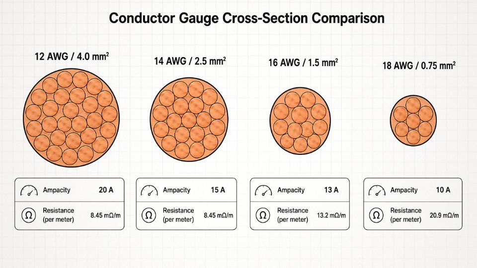
A 10-meter 18 AWG copper cord adds approximately 0.33Ω of resistance, causing measurable voltage drop and heat generation under full rated load.True
Based on copper resistivity of 1.68 × 10⁻⁸ Ω·m and 18 AWG cross-section of approximately 0.823 mm², resistance per meter is roughly 20.9 mΩ/m. Over 10 meters of two-conductor cord (current travels out and back), total added resistance is approximately 0.33Ω, consistent with known wire tables.
Stranded vs. Solid — Don’t Mix These Up
Flexible power cords use stranded copper conductors. Always. A stranded conductor survives thousands of flex cycles because the load distributes across many fine wires; solid copper work-hardens and eventually cracks at flex points. Solid conductors belong in fixed conduit wiring inside walls and panels, not in anything that gets plugged and unplugged or moved around equipment. Using a solid-conductor cable as a “temporary” power lead is a maintenance habit worth correcting immediately.
Conductor Count and Purity
Standard mains cords are three-conductor: line, neutral, and ground. The ground conductor is not optional for anything connected to a grounded outlet — it’s the fault-current path. Two-conductor cords still exist for Class II double-insulated equipment, but you’ll see them less frequently in industrial settings. Some machine tool applications call for four or five conductors to carry control signals alongside mains power, which is why reading the full jacket marking matters.
On conductor purity: oxygen-free copper (OFC) and standard electrolytic tough-pitch copper (ETP) differ by only about 1–2% in resistivity. For most power cord applications that difference is negligible. Where it becomes relevant is precision measurement equipment or high-frequency signal-carrying cables where even marginal resistance differences affect performance. For bulk industrial power cord procurement, ETP copper at the correct gauge is almost always sufficient.
Reading the Jacket Marking
A cord marked “18 AWG 3C” means three conductors, each 18 AWG. The European equivalent “3×0.75 mm²” means the same thing in metric. If the jacket shows “3×1.5 mm²/300V/70°C”, you know conductor size, voltage rating, and maximum operating temperature all at once. Learn to read these markings rather than relying on connector size or cord diameter alone — a C13-terminated cord can be built on several different gauges depending on the manufacturer, and the one with the thinner conductors will run hotter under the same load.
Insulation Temperature Ratings and Their Hidden Role in Wattage Limits
Gauge gets all the attention in procurement conversations, and that’s understandable — it’s stamped on the cable, easy to verify, easy to specify. But two cords can share identical 16 AWG conductors and still have meaningfully different safe wattage ceilings in practice. The reason is insulation, and specifically how much heat the insulation can absorb continuously before it starts to degrade, soften, or worse.
Joule Heating Is Always Happening
Every time current flows through a conductor, resistance converts some of that electrical energy into heat. That’s not a fault condition — it’s physics. At moderate loads it’s trivial. Push the conductor toward its rated limit, run it inside a conduit bundle, or operate it in a warm equipment cabinet, and that heat accumulates faster than it dissipates. The insulation surrounding the conductor is what sits between acceptable operating temperature and a slow-motion fire hazard.
The insulation doesn’t just protect the conductor from mechanical damage. It defines the thermal ceiling the cord can live under, continuously, for its rated service life — usually somewhere in the range of 10 to 25 years depending on application and cycling frequency. Once that ceiling is breached regularly, the polymer chains in the jacket begin to break down. PVC gets brittle and cracks. Rubber vulcanization reverses. You end up with insulation that looks fine from the outside and crumbles when you flex it.
Standard Temperature Classes and What They Actually Mean for Wattage
UL-listed power cords in North America carry temperature designations that are part of the cable type designation itself, not a separate label. The common ones:
- 60°C — standard PVC, covers types SPT, SVT, and similar light-duty cords. Fine for lamps, small appliances, typical office equipment. Cheapest option and perfectly adequate in a 20–25°C indoor environment.
- 75°C — thermoplastic insulation, type SJT and variants. Allows roughly 5–15% more continuous current for the same conductor size compared to a 60°C-rated cord, depending on the derating table. Common in workshop tools and mid-duty equipment cords.
- 90°C — XLPE (cross-linked polyethylene) or silicone, types SJTO, STO, and similar. Industrial, high-cycle, or elevated-ambient applications. At 90°C rating, NEC and IEC derating tables permit noticeably higher ampacity from the same gauge — which directly translates to higher safe wattage.
That gap between 60°C and 90°C insulation on a 16 AWG conductor can represent a real-world ampacity difference of roughly 2–4A depending on installation conditions. On a 120V circuit that’s 240–480W of additional headroom. Not trivial if you’re specifying cords for equipment running at 80–90% of rated load.
Derating for Ambient Temperature — Often Ignored Until Something Burns
Standard ampacity tables assume a 30°C ambient. That’s a reasonable assumption for an air-conditioned office. It is not a reasonable assumption for a server room with a failing CRAC unit in July, a factory floor near a kiln, or any cord running inside a machinery enclosure where the ambient easily reaches 45–55°C.
A power cord operating in a 50°C ambient environment may only safely carry 70–80% of its nameplate ampacity.True
NEC Table 310.15(B)(2)(a) and IEC 60364-5-52 both publish correction factors for elevated ambient temperatures. At 50°C ambient with a 60°C-rated insulation, the correction factor drops to approximately 0.71–0.82 depending on conductor size and installation method, which directly reduces the allowable continuous current and therefore the safe wattage the cord can handle.
In practice, engineers often forget to apply derating when equipment gets moved from a climate-controlled lab into a production environment. The cord that passed qualification testing at 22°C starts running hot at 47°C ambient. It won’t trip a breaker immediately. It will just cook slowly until the jacket cracks or a connection point arcs.
Insulation Materials Beyond Basic PVC
Rubber-jacketed cords — SO, SOW, and SOOW types — offer better flexibility and oil resistance than PVC, which is why they dominate on factory floors and in outdoor equipment. TPE and TPU jackets are increasingly specified where halogen-free flame retardancy is required, particularly in European industrial equipment and transit applications. XLPE sits at the top for high-temperature stability; it’s radiation cross-linked during manufacture, which fundamentally changes the polymer structure compared to standard thermoplastic.
In commercial buildings, data centers, and marine installations, low-smoke zero-halogen (LSZH) requirements add another layer of constraint on top of temperature ratings. An LSZH cord in a 90°C-rated construction costs more — sometimes 30–60% more per meter than a standard PVC equivalent — but in a data center or shipboard environment where evacuation routes depend on limiting toxic smoke, the specification is non-negotiable. Procurement teams sometimes try to substitute standard flame-retardant PVC to cut cost. That’s a mistake that shows up in insurance audits or, worse, incident investigations.
Reading the Markings in Procurement
On UL-listed cords, the cable designation carries the temperature rating directly: SVT 300V 60°C is unambiguous. For IEC cords sold into European markets, look for HAR harmonized marking — a string of letter codes where the temperature class appears as a numeral suffix in the conductor insulation designation. An H05VV-F cord is rated 60°C; H05RR-F is rubber-insulated with a 60°C rating but better mechanical resilience; H07RN-F steps up to heavier rubber construction at 60°C nominal but significantly better thermal and mechanical performance in practice.
If a supplier’s datasheet lists gauge and voltage rating but omits temperature class, ask before ordering. That omission is not a minor gap — it’s the difference between a cord that handles its rated wattage safely in your actual installation environment and one that degrades within a year.
Connector and Plug Ratings: Where the Wattage Chain Can Fail
A power cord assembly is only as capable as its weakest component. You can spec 14 AWG conductors with 90°C insulation and still end up with a fire hazard if the connector at the end is a cheap C13 body with thin phosphor-bronze contacts and loose retention. The conductor sets one ceiling. The insulation sets another. The connector — both the plug end and the appliance coupler — sets a third, and in practice it’s the one most often ignored during procurement.
The IEC 60320 Family: More Variation Than Most People Realize
IEC 60320 covers a wide range of connector types, and the wattage limits spread across them are not subtle differences. The C1/C2 pairing (those tiny two-pin connectors on old shavers) is rated at 2.5A — roughly 250–625W depending on voltage. The C5/C6 “cloverleaf” or “Mickey Mouse” connector seen on laptop bricks shares that 2.5A ceiling. C7/C8, the figure-8 used on radios and some AV gear, is the same. None of these belong anywhere near a space heater or industrial power supply, yet they turn up in gray-market assemblies attached to heavier cable, which is a real procurement failure mode.
The workhorse of data centers and IT equipment is the C13/C14 pair, rated at 10A continuous — 1,250W at 125V, 2,500W at 250V. That’s a meaningful difference depending on where the equipment ships. The C15/C16 looks nearly identical to C13/C14 but carries a 120°C temperature rating for kettle leads and similar high-temperature applications; the notch position distinguishes them physically, which prevents accidental substitution. For higher-density server racks and industrial UPS outputs, C19/C20 steps up to 16A — around 4,000W at 250V. C23/C24 handles the same 16A but in a different form factor used mainly in European rack systems.
North American NEMA Plugs: The Voltage Multiplier Effect
NEMA 5-15 is the standard North American 15A plug everyone recognizes — rated 1,875W at 125V. NEMA 5-20, with its T-shaped neutral slot, handles 20A/2,500W on the same 125V circuit. Switch to 250V circuits and the math changes fast: NEMA 6-15 carries 15A at 250V, which works out to 3,750W, and NEMA 6-20 reaches 5,000W at 250V. For genuinely heavy industrial loads — welding equipment, large motor drives, high-wattage process heaters — NEMA L6-30 twist-lock connectors handle 30A at 250V, or up to 7,500W. The twist-lock design isn’t just about current capacity; it’s about keeping the connection mechanically stable when vibration or cable pull would otherwise cause intermittent contact and arcing.
Contact Resistance: The Slow Failure Mode
Oxidized or corroded contacts add resistance at exactly the point where clamping pressure is highest and heat dissipation is worst. A connection that measures 0.01Ω when new can creep toward 0.1Ω or higher after months in a humid or corrosive environment, and the power dissipated at that joint rises with the square of current. At 16A through a degraded contact, that’s not a rounding error — it’s a heat source. Gold-plated contacts are specified in high-cycle environments (server room PDUs, medical equipment) and in humid climates for this reason, not as a luxury tier.
Standard IEC 60320 connectors are rated for 5,000–10,000 insertion cyclesTrue
IEC 60320-1 specifies mechanical endurance testing; standard grades target this range, while industrial-rated equivalents (such as IEC 60309 types) are tested to 25,000 cycles or more, making connector grade selection critical for factory or data-center environments with frequent plugging cycles.
In a factory context — think test benches where cords get swapped daily — a standard C13 connector reaches end of life faster than anyone budgets for. Contacts work-harden and lose clamping force; the retention friction drops; voltage drop climbs. Industrial-grade IEC 60309 plugs (the round, color-coded industrial standard) address this with higher contact mass, better spring retention, and those 25,000-cycle ratings. For high-wattage environments where accidental disconnection could drop a production line or, worse, cause a mid-cycle arc, locking connectors aren’t optional.
Termination Method Matters Too
The connection between conductor and connector body — how the wire actually attaches — is part of the same chain. Crimped terminations done with calibrated tooling to the connector manufacturer’s spec are consistent and auditable. Soldered joints depend heavily on operator skill and can wick solder into the conductor’s flex zone, creating a stiff spot that fatigues and cracks under repeated bending. Screw-terminal connections, common in field-wireable plugs, will loosen under thermal cycling if not torqued correctly and re-checked. A practical procurement checklist before approving a cord assembly: verify that the plug ampere rating, the coupler ampere rating, and the termination method are all equal to or above the conductor’s rated current — not just the device’s nameplate wattage. One weak link in that chain and the rest of the specification is irrelevant.
International Standards and Certification Marks That Define Wattage Compliance
A manufacturer printing “1800W” on a cord jacket means nothing on its own. That number only carries legal and engineering weight when an accredited third-party body has tested the cord under defined conditions and issued a certificate. In practice, uncertified cords sourced from unvetted suppliers often fail — thermally or electrically — at somewhere between 60% and 75% of the claimed rating, depending on conductor quality, insulation compound, and connector contact resistance. For a procurement manager signing off on a container of cord sets destined for hospital equipment or industrial machinery, that gap is the difference between a compliant product and a liability.
An uncertified power cord marked '1800W' may actually fail below 1200W under real operating conditionsTrue
Without third-party testing at elevated ambient temperatures and under sustained load, manufacturer-stated wattage ratings are unverified. Poor conductor purity, thin insulation, and high-resistance connectors can cause thermal failure well below the printed figure.
North American Certification: UL and CSA
In the US and Canada, the relevant standards split by product type. UL 62 covers the flexible cord itself — the cable as a raw material. UL 817 covers the complete cord set: cable plus molded or assembled connectors tested as a unit. CSA C22.2 No. 49 is the Canadian parallel to UL 817. The distinction matters enormously for industrial procurement. A UL 62-listed cable paired with a non-listed connector is not a UL 817-listed cord set. AHJs (Authorities Having Jurisdiction) and OEM compliance departments will catch this, often late in a product launch cycle at significant cost.
UL’s ampacity testing for cord sets is not done at 20 °C room temperature. Tests run at elevated ambient — typically around 60 °C for the connector housing surfaces — which is why a cord that passes comfortably in a cool lab can run hot in a server room or near furnace exhaust. Specify the ambient conditions in your purchase order, not just the wattage figure.
European Framework: HAR, IEC Standards, and ENEC
Europe uses a harmonized system. The HAR mark (from the CENELEC agreement) indicates the cord was manufactured and tested to a harmonized standard — IEC 60227 for PVC-insulated flexible cords, IEC 60245 for rubber-insulated types. CE marking on a cord set signals self-declared conformity to EU Low Voltage Directive requirements, but CE alone is not third-party verified. ENEC certification, issued by accredited European test bodies, is the mark that carries independent verification and is accepted across most EU member states without re-testing. For pan-European distribution, specifying ENEC rather than just CE is the cleaner procurement call.
Asia-Pacific and Emerging Markets
Each major market runs its own regime. China requires CCC (China Compulsory Certificate) for cords sold domestically — tested to GB standards with wattage and temperature-rise limits verified by CNCA-designated labs. Japan’s PSE mark covers two categories: the diamond PSE for regulated products (including cord sets), tested by registered inspection bodies. South Korea uses KC certification under the Electrical Appliances Safety Act. Australia and New Zealand require RCM (formerly the SAA mark), which references AS/NZS 3191 and related standards. India’s BIS certification under IS 694 is mandatory for PVC flexible cables. Each of these schemes specifies its own test temperatures, load durations, and connector requirements — a cord certified to UL 817 does not automatically meet PSE or BIS conditions.
The Cord vs. Cord Set Distinction
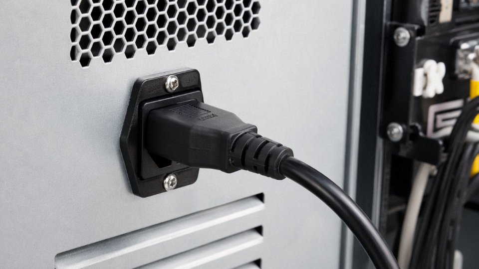
This is the sourcing trap that catches buyers repeatedly. A certified cable and a certified connector do not equal a certified cord set. The complete assembly — cable, strain relief, molded plug, and termination — must be tested and listed as a unit. Always specify the cord set certification on your purchase requisition, with connector model and cable gauge called out explicitly.
RoHS, REACH, and LSZH Constraints
RoHS and REACH restrictions limit which plasticizers and flame retardants can go into insulation compounds. In practice, this narrows the field of compliant high-temperature insulation materials, which indirectly caps wattage ratings for a given gauge — a cord that could theoretically handle 90 °C insulation temperature with an unrestricted compound may only be certifiable to 75 °C using RoHS-compliant materials. LSZH (Low Smoke Zero Halogen) requirements, common in tunnels, rail, and marine applications, tighten this further. Budget for a slightly heavier gauge or a larger connector when LSZH is mandatory and your load runs near the rating ceiling.
Reading a Test Report Correctly
When a supplier hands you a CB scheme certificate under the IECEE system, check three things before accepting it: the exact product code tested (connector model, cable construction, gauge), the ambient test temperature, and the date — CB certificates can age out if the product has been revised. Cross-reference the certificate number directly on the issuing National Certification Body’s database. If the tested wattage was verified at 25 °C ambient and your deployment environment runs at 45 °C, that certificate does not fully cover your application, regardless of what the spec sheet says.
Real-World Wattage Mismatch Failures: Case Studies and Root Cause Analysis
These aren’t hypothetical edge cases. Every failure type below shows up repeatedly in field investigations, warranty returns, and insurance reports. The physics is always the same — the cord was asked to do more than it was built for, and something in the assembly gave way first.
Office Extension Cord Fire: Undersized Gauge, No Derating
An 18 AWG SPT-2 cord — the kind sold in blister packs at hardware stores, rated 10A — gets pressed into service powering a row of workstations: monitors, desktop towers, a laser printer cycling on and off. Total draw works out to roughly 2,200W at 120V, meaning current around 18–19A. The cord’s copper is sized for 10A continuous. At nearly twice that load, I²R heating climbs fast. Insulation surface temperatures in documented incidents like this have reached 130–150°C before a 20A branch circuit breaker trips — and many older offices still have 15A breakers that trip even later in the fault sequence because the breaker is protecting the wiring in the wall, not the extension cord on the floor.
The root cause isn’t just “too many devices.” It’s that nobody applied the 80% continuous-load derating rule. A 10A-rated cord should carry no more than 8A on a sustained basis. That single discipline — running the numbers before plugging in — eliminates most of these events.
CNC Machine Intermittent Faults: Correct Gauge, Degraded Connector
A CNC machining center drawing around 14A at 240V developed intermittent PLC undervoltage alarms — the kind that are maddening to diagnose because they don’t repeat on demand. The cord set itself was 14 AWG, perfectly adequate for the load. The problem was an oxidized C14 inlet connector, probably 3–4 years old and never inspected. Contact resistance at that connector measured in the range of 0.2–0.3Ω. At 14A, that’s roughly 2.5–3V of drop right at the connector body and somewhere between 35–45W of heat dissipating in a connector rated for 10A continuous — because someone had grabbed a standard C13/C14 cord set instead of a C19/C20 assembly rated for 16A.
The machine wasn’t failing randomly. It was failing whenever the spindle load spiked. Thermal imaging during a production run showed the connector housing glowing at 70–80°C above ambient. Swap to a properly rated C19/C20 cord set with fresh contacts, re-torque the strain relief, and the faults stopped immediately.
A C13/C14 IEC connector is rated for 10A continuous, not 16A, and should not be used as a substitute for C19/C20 in circuits where load regularly exceeds 10A.True
IEC 60320 defines C13/C14 at 10A and C19/C20 at 16A. Using the lighter connector at higher continuous loads causes resistive heating at contact points, accelerated oxidation, and eventual failure — regardless of the cord gauge feeding it.
Data Center PDU Cord Failure: Ambient Temperature Ignored
Servers pulling 9.5A each, fed by 10A IEC C13 cords. On paper, 95% of rating sounds acceptable. In a hot-aisle environment running 42–46°C ambient, it isn’t. Most cord derating tables are referenced to 30°C. At 45°C ambient, a cord’s effective continuous capacity drops by roughly 15–20%, depending on insulation class and bundling density. PVC insulation rated 60°C has almost no headroom left. The result in this scenario: insulation softening, eventual jacket-to-jacket adhesion in bundled runs, and a ground fault that took down a cabinet.
The fix costs almost nothing — specify 75°C or 90°C rated insulation for hot-aisle deployments, or derate to 7–8A per cord and add circuits. Neither is complicated. The failure is purely a specifying error.
Export Product Recall: Regional Standard Mismatch
A manufacturer ships equipment into North America with power cords certified 250V/10A under European standards — legitimate CE-marked cords, proper gauge, proper connectors for the EU market. North American customers run them on 120V/15A circuits. The voltage is lower, so the electrical stress looks fine on paper. But the connector is not NEMA-rated, the plug geometry doesn’t fully engage some receptacles, and the housing material wasn’t evaluated under UL or CSA protocols. Physical connector failures — cracked housings, partial insertions, intermittent grounds — triggered a recall. The cord wasn’t electrically overloaded. It failed mechanically in a socket it was never tested for.
This is a procurement problem as much as an engineering one. Certification of a cord assembly must cover the entire assembly for the target market, not individual components tested in isolation.
Common Lessons Across All Four Cases
The 80% continuous derating rule appears in NEC, IEC guidance, and every experienced plant electrician’s mental model — yet it gets skipped constantly. Ambient temperature correction is a separate multiplier, not an alternative to derating. Connector ratings are an independent constraint from conductor gauge; a heavy cable with an undersized or worn connector is still a failed assembly.
A practical supply-chain audit of power cord assemblies should include at minimum: pull-force testing on connector terminations (typical acceptance thresholds run 40–80N depending on connector class), insulation resistance measurement at 500V DC between conductors and between live conductors and ground, and thermal imaging under 100% rated load for a 30-minute soak. Visual inspection alone misses oxidized contacts and marginal crimp terminations almost every time. The thermal camera doesn’t lie.
Selecting the Right Wattage-Rated Power Cord: A Practical Specification Framework
By the time you’ve worked through conductor gauge, insulation class, connector ratings, and certification marks, you have all the technical knowledge you need. The problem is turning that knowledge into a purchase order line item before a project deadline. Here’s a sequence that works on the plant floor and in the procurement office.
Step 1 — Establish the Actual Device Load
Start at the nameplate. Read the watts or VA rating directly; don’t guess from the product category. A “1500W” space heater is a resistive load and draws close to that continuously. A 1500W motor-driven compressor can pull 3–5× that rating for 200–400 ms during startup — the nameplate only tells you steady-state.
If the nameplate shows VA rather than watts, multiply by a power factor of 0.8–0.9 for most industrial equipment (lower for older motors, closer to 1.0 for resistive heaters). No nameplate at all? Use a clamp meter under actual operating conditions and log the peak, not just the steady reading. Once you have your real number, add a 25% margin on top specifically to absorb motor inrush, compressor cycling, and load transients. That figure is your design load.
Step 2 — Apply the 80% Continuous Derating Rule
Divide your design load by 0.8. A device pulling 1440W continuous requires a cord rated at minimum 1800W. This isn’t a conservative nicety — it’s the basis of UL and IEC continuous-operation ratings. Running a cord at 100% of its rating for hours at a time causes cumulative insulation degradation that shows up six months later, not today.
Step 3 — Convert to Ampacity and Match Voltage System
Watts ÷ volts = amps. A 1800W requirement on a 120V circuit demands 15A; on a 230V circuit, that same load only needs 7.8A, which is why cord ratings look very different between North American and European catalogs. Confirm which voltage system the installation uses before specifying gauge — a cord sized for 230V service will be under-gauged if someone plugs it into a 120V circuit serving a higher-amperage device.
Step 4 — Select Conductor Gauge and Insulation Class
Cross-reference your required ampacity against the AWG/mm² table. 18 AWG (0.75 mm²) handles up to roughly 10A; 16 AWG (1.0–1.5 mm²) up to 13A; 14 AWG (2.5 mm²) up to 15A under standard conditions. Those ceilings drop meaningfully when cords run inside conduit, bundle together, or operate in ambient temperatures above 40°C. In those environments, bump up one gauge size and specify 105°C-rated insulation (XLPE or high-grade PVC) rather than standard 60°C or 75°C material.
Step 5 — Specify the Connector Type and Rating
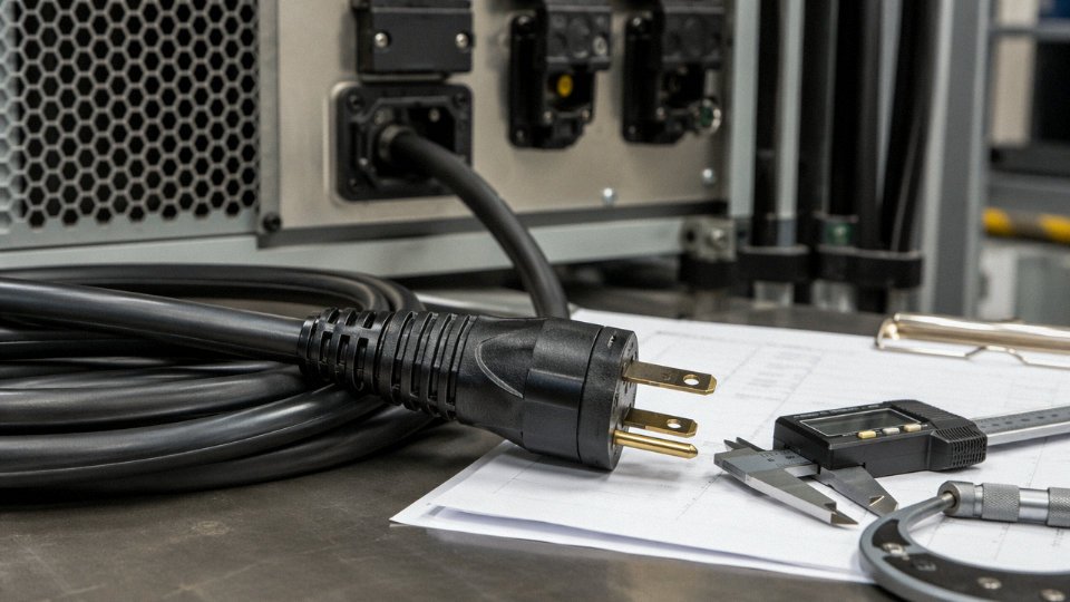
The connector is where many procurement decisions go wrong. An IEC 60320 C13/C14 connector is rated at 10A continuous — it doesn’t matter if the cord behind it is 14 AWG capable of 15A. If your load requires 16A, you need C19/C20 or an equivalent industrial connector. For outdoor installations or wash-down environments, specify IP44 or IP67 rated connectors and confirm the IP rating applies to the mated condition, not just the plug in isolation.
An IEC 60320 C13 connector is rated for 10A continuous regardless of the conductor gauge used in the attached cord.True
IEC 60320 defines connector contact ratings independently from conductor ratings. Pairing a C13 connector with a heavier-gauge cord does not raise the connector's 10A ceiling — the connector remains the limiting element in the wattage chain.
Step 6 — Budget for Voltage Drop Over Cord Length
Calculate the resistive drop: voltage drop = current × total conductor resistance (both legs). Copper resistivity is approximately 1.68 × 10⁻⁸ Ω·m; a 10-meter 18 AWG cord adds roughly 0.33Ω, which at 10A means a 3.3V drop — around 2.75% of 120V, acceptable for general loads, borderline for sensitive electronics. Keep drop below 3% for instrumentation and PLCs, below 5% for motors and heaters. If a longer run pushes you past that threshold, go up one gauge rather than accepting the loss.
Step 7 — Specify Certifications in the Purchase Order
A declaration of conformity costs nothing to print. Require actual test reports. For US market: UL 62 or UL 817 listing. European market: HAR approval under HD 21 or HD 22. China domestic: CCC under GB/T 5023. Other markets have their own requirements — confirm before the shipment lands, not after customs flags it.
Quick-Reference Specification Checklist
| Step | Action | Key Output |
|---|---|---|
| 1 | Read nameplate; measure with clamp meter if needed; add 25% for surge | Design load (W or VA) |
| 2 | Divide design load by 0.8 | Minimum cord wattage rating |
| 3 | Divide by supply voltage; confirm voltage system | Required ampacity (A) |
| 4 | Match AWG/mm² to ampacity; adjust for temperature and bundling; select insulation class | Conductor gauge + insulation grade |
| 5 | Confirm IEC 60320 or NEMA connector matches ampacity; specify IP rating if needed | Connector type and rating |
| 6 | Calculate I × R drop for total cord length; stay below 3–5% of supply voltage | Maximum acceptable cord length |
| 7 | List required certification marks in PO; request test reports | Market-legal, documented cord |
In practice, steps 2 and 7 are the ones most often skipped under schedule pressure. Skipping step 2 causes the thermal failures described earlier. Skipping step 7 causes shipment holds, returns, and liability exposure. Neither outcome is recoverable cheaply.
Frequently Asked Questions About Power Cord Wattage
Can I use a higher-wattage-rated cord than my device requires?
Yes, always. A cord rated above your device’s draw simply runs cooler and lasts longer — there is no electrical penalty for overrating. If your laser printer pulls 8A and you wire it with a 14 AWG cord rated for 15A, that cord will barely get warm. In practice, slightly overrating is a reasonable procurement habit, especially on cords that will run continuously or in warm ambient conditions. The only real downside is marginal cost and, occasionally, stiffer cable that’s harder to dress neatly in a tight equipment bay.
Using a power cord rated higher than the device's wattage requirement creates a safety risk.False
A higher-rated cord carries the load with lower resistive heating and no added risk. Overrating a cord is a standard engineering practice for derating and thermal margin.
What happens if I use an undersized cord for a high-wattage device?
The cord overheats. Resistance in the conductor converts excess current to heat, and at sustained overload that heat degrades the insulation — first softening it, then cracking it, eventually exposing bare copper. The failure timeline depends on how far over-rated the cord is being pushed and the ambient temperature; a moderately undersized cord in a 45°C machine room might fail in months rather than years.
The circuit breaker usually won’t save you here. Breakers protect the building wiring and the circuit, not the cord plugged into it. A 15A breaker won’t trip if a 10A-rated cord is passing 13A — that’s within the breaker’s range, but it’s above the cord’s safe continuous capacity. This is a common misunderstanding on the plant floor, and it’s the root cause of a good portion of cord fires in industrial settings.
Does cord length affect wattage capacity?
It does, and this one catches people off guard. Copper resistivity is fixed at roughly 1.68 × 10⁻⁸ Ω·m — a 10-meter 18 AWG cord adds about 0.33 Ω of resistance, which causes measurable voltage drop and additional heat at high load. For runs beyond 15 meters carrying near-rated loads, step up one gauge size. A job that’s fine on 16 AWG at 3 meters may need 14 AWG at 20 meters to stay within acceptable voltage drop and thermal limits.
Are power cords rated in watts, or in amps?
Most cords are rated in amperes and volts. Wattage capacity is derived: P = V × I. An IEC C13 cord rated 10A at 250V can handle 2500W on a 250V circuit, but only 1200W on a 120V circuit. Always check both values and do the arithmetic for your actual supply voltage — don’t assume the printed wattage on a cord label applies to your system.
Does the cord jacket color affect wattage rating?
No. Color is an identification convention, nothing else. Black, gray, white, orange — the wattage capacity is set entirely by conductor cross-section, insulation temperature class, and connector rating. An orange jacket on a construction-site cord signals outdoor duty to workers; it does not change the copper inside.
Can a 250V-rated cord be used on a 120V circuit?
Yes, safely. A higher voltage rating is conservative at lower voltages. The insulation is built to withstand more electrical stress than it will actually see. The wattage capacity at 120V will be roughly half what it is at 240V for the same amperage rating — that’s just the P = V × I math, not a limitation of the cord itself.
How do I know if an extension cord is heavy enough for power tools?
Look for 14 AWG minimum — 12 AWG if the run is long or the tool is a heavy grinder or compressor. The cord should be three-prong grounded, rated 15A or 20A, and carry a UL or ETL listing for the market it’s used in. Avoid SPT-type zip cord (typically 18 AWG, flat jacketed) for anything drawing over roughly 1000W. That type is built for lamps and small electronics, not sustained tool loads.
What is the difference between a power cord and a power cord set?
A power cord is the cable alone — the conductors, insulation, and outer jacket. A power cord set, sometimes called a cord assembly, is the complete unit: cable plus molded or field-attached connectors at one or both ends. For regulatory compliance in most markets, the certification must cover the complete assembly, not just the cable portion. Buying certified cable and attaching uncertified connectors produces a non-compliant assembly, regardless of how good the cable is individually. This distinction matters a lot in procurement: specify cord sets with end-to-end certification, not just certified bulk cable.
How Jinda Manufactures Wattage-Compliant Power Cords for Global Industrial Projects
Jinda has been producing flexible cables and cord sets from Shandong, China since 1987 — long enough to have watched the IEC 60320 family evolve through multiple revisions and to have retooled production lines when North American UL requirements tightened on conductor cross-section tolerances. That kind of institutional memory matters when a procurement manager is trying to consolidate supply across three continents under a single vendor.
Five production bases, roughly 470,000 m² of manufacturing floor, and over 1,000 employees give the operation a scale that genuinely supports long-term industrial supply contracts — not just sample orders. Customers in more than 50 countries pull from this infrastructure, ranging from OEM appliance manufacturers placing multi-million-meter annual orders to project contractors needing custom cord assemblies for a specific regional rollout.
Vertical Integration as a Wattage Control Strategy
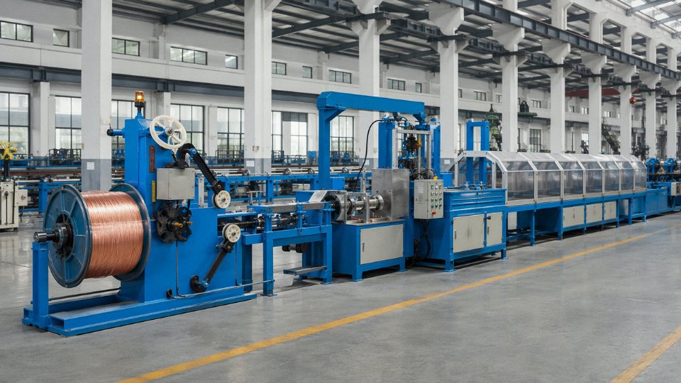
The detail that matters most for wattage compliance is how much of the process Jinda controls in-house. Conductor drawing, stranding, insulation extrusion, jacketing, connector assembly, and final cord-set testing all happen under one quality system. That means when a 14 AWG cord set leaves the facility rated for 15A/1875W at 125V, every variable that determines that rating — conductor cross-section, strand count, insulation wall thickness, jacket material — has been measured and logged internally rather than inferred from a supplier’s certificate.
In practice, that traceability closes the gap that causes most wattage-related field failures: a conductor that tests slightly undersized because it came from an external drawing house with a different tolerance window. It is a mundane problem, but it produces real consequences — elevated resistance, localized heating, insulation degradation over 12 to 18 months of continuous use.
Quality Controls Specifically Targeting Wattage Limits
Conductor cross-section is measured by laser micrometer at multiple production intervals — not just sampled at end-of-line. Insulation spark testing runs at twice the rated voltage, which catches wall defects that would survive a single-voltage continuity check but fail under thermal stress at high load. Thermal aging ovens qualify insulation batches before production release, simulating long-term exposure at rated temperature classes. Cord sets then go through load cycle testing at both 100% and 80% rated current to verify connector contact resistance and conductor temperature rise stay within the limits that underpin the wattage rating.
That 80% figure is not arbitrary — it mirrors the NEC continuous load derating rule and reflects how most industrial equipment actually runs in the field. Testing at nameplate current only would miss the thermal behavior that matters for real-world uptime.
Certifications Across Every Major Market
Jinda holds UL, HAR, CCC, PSE, KC, SAA/RCM, and ENEC certifications for power cord assemblies.True
These certifications cover the primary regulatory requirements for North America (UL), Europe (HAR, ENEC), China (CCC), Japan (PSE), South Korea (KC), and Australia/New Zealand (SAA/RCM), enabling compliant supply across Jinda's main export markets without customers managing separate compliance submissions.
That portfolio means a procurement team sourcing for a simultaneous product launch in the US, Germany, and Australia can receive compliant cord sets from a single purchase order rather than managing three separate qualification processes.
Customization Without Compromising the Rating
Custom lengths run from 0.5 m to 30 m. Jacket materials include PVC, rubber, TPU, and LSZH — each with different temperature ratings and flex-cycle endurance, which affects the wattage ceiling in ways the earlier sections of this article cover in detail. IEC, NEMA, and proprietary connector configurations are all supported, along with private labeling and full OEM documentation packages.
Annual flexible cable production exceeds 50 million meters, and warehouse stock of common cord set configurations keeps lead times short for standard specifications.
Engineers and procurement managers with a defined specification are invited to submit it for technical review. Jinda’s application engineers will verify wattage compliance against the target market’s standard before production begins — catching mismatches at the design stage rather than during a compliance audit.