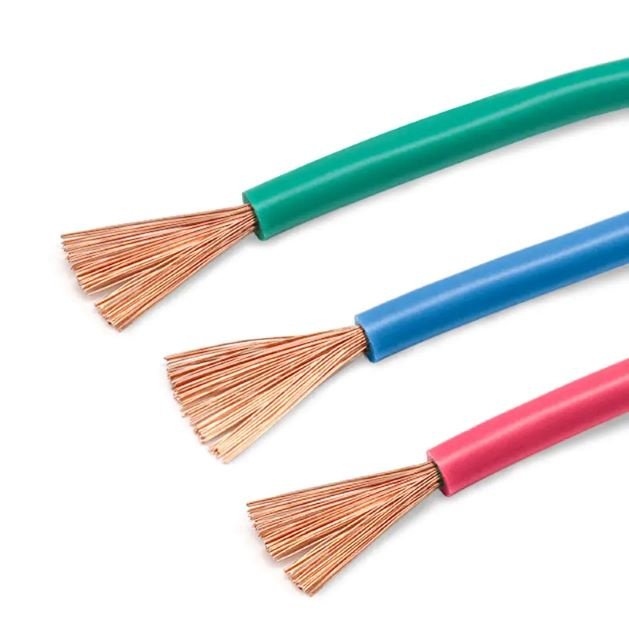
A cable sitting coiled in a warehouse feels inert — it looks like nothing more than insulated copper or aluminum. That mental model gets people hurt and plants shut down. Maintenance technicians who assume a de-energized label means a truly dead cable have walked into arc flash events. Procurement managers who spec the wrong insulation class for an energized run end up replacing cable after the first overload, sometimes inside twelve months of commissioning. The question of whether a cable wire “has electricity” is not a beginner question at all — it determines installation method, PPE requirements, grounding strategy, and total cost of ownership across the system.
A cable wire carries electricity only when it forms part of a closed circuit connected to a live source — the conductor itself has no inherent charge. Whether any given cable is energized at a specific moment depends on switching state, system topology, and residual charge from capacitance. Low-voltage power cables rated to IEC 60502 (0.6/1 kV) can carry anywhere from 10 A to over 400 A depending on cross-section, and copper conductors with a resistivity of roughly 1.72 × 10⁻⁸ Ω·m at 20°C will do so with less heat loss than aluminum at 2.82 × 10⁻⁸ Ω·m — but both will kill you if you treat them casually.
What makes this genuinely complicated is that a cable can be de-energized at the panel, perfectly isolated by a lockout, and still hold a charge — capacitive coupling from adjacent runs, induced voltage from nearby transformers, or simply a switching error upstream. Understanding how electricity behaves inside a cable, what governs its presence or absence, and what physical and regulatory factors separate a safe conductor from a hazardous one is worth working through carefully.
How Cable Wire Is Built: Conductors, Insulation, and Sheathing Layers
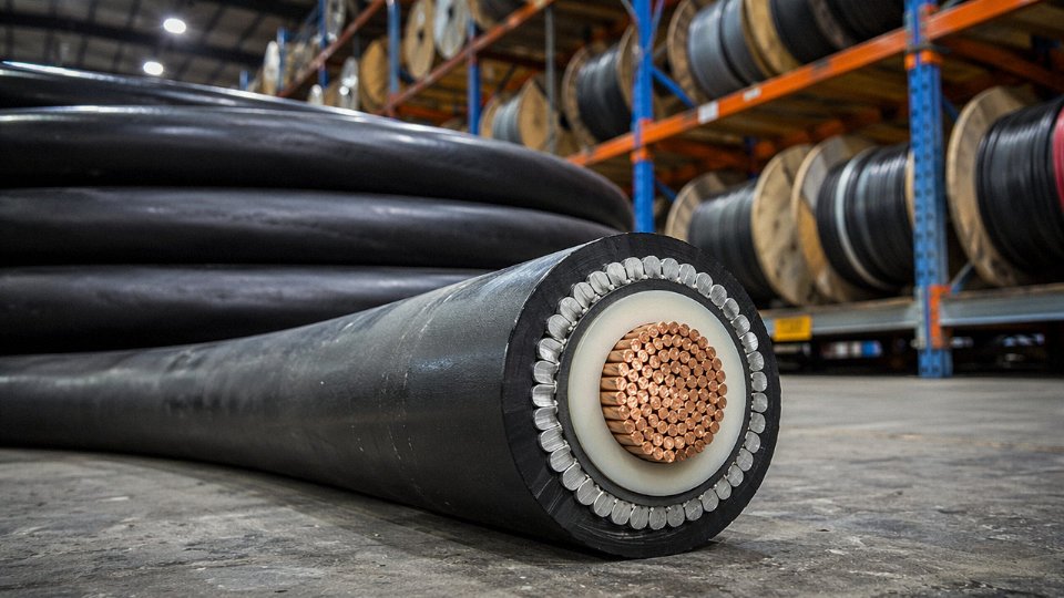
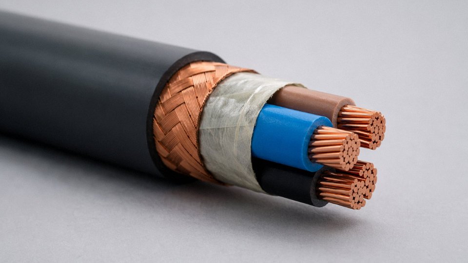
Strip back any power cable and you’ll find a logical stack of layers, each doing a specific job. Understanding what each one does — and which ones actually carry current — matters whether you’re specifying a cable for a new feeder run, troubleshooting a fault, or evaluating a supplier’s product sheet.
The Conductor Core: The Only Layer That Moves Current
The conductor is the functional heart of any power cable. It’s the only layer designed to carry electrical current, and everything else exists to support, protect, or isolate it.
Most power cable conductors are copper or aluminum. Copper sits at roughly 1.72 × 10⁻⁸ Ω·m resistivity at 20°C; aluminum runs about 2.82 × 10⁻⁸ Ω·m under the same conditions — meaning for the same cross-section, aluminum conducts less efficiently and typically needs to be upsized by one or two cross-section steps to match copper’s ampacity. Which material you choose depends on weight constraints, installed cost, jointing complexity, and local procurement pricing. In my experience, aluminum feeders are common in large industrial plants and utility distribution work where weight and material cost matter; copper dominates in tight conduit runs, flexible applications, and anywhere termination quality is hard to control.
Cross-sections in commercial production range from 1.5 mm² for residential lighting and socket circuits up to 630 mm² or larger for heavy industrial feeders and substation connections. Current-carrying capacity at those extremes varies enormously — a 1.5 mm² copper conductor might carry 15–20 A in free air, while a 630 mm² conductor can handle well over 800 A depending on installation method, ambient temperature, and grouping.
IEC 60228 classifies conductors by flexibility. Class 1 is solid wire, common in smaller residential sizes. Class 2 is the standard stranded conductor you’ll find across most industrial and commercial cable. Class 5 is the finely stranded, flexible conductor used in trailing cables, machine tools, and anything that sees repeated movement. Specifying the wrong class for a flexing application causes work-hardening and conductor fatigue — a failure mode that shows up as intermittent faults weeks or months after commissioning, by which point the root cause isn’t obvious.
Insulation: The Layer That Keeps Current Contained
Wrapped directly over the conductor is the insulation layer — PVC, XLPE (cross-linked polyethylene), or EPR (ethylene propylene rubber) being the most common choices. This layer is non-conductive by design. Its job is to prevent current from escaping the conductor under normal operating conditions.
Voltage rating is where insulation specification gets critical. Standard low-voltage cables per IEC 60502-1 are rated 0.6/1 kV and cover the bulk of industrial power distribution. Medium-voltage cables step up to 6/10 kV, 12/20 kV, or 18/30 kV and ultimately 26/35 kV, with insulation wall thickness increasing accordingly. XLPE is the standard choice for medium-voltage and above because of its superior thermal performance — continuous conductor temperatures up to 90°C versus 70°C for standard PVC — and its lower dielectric losses over longer cable runs. EPR shows up in shipboard and offshore applications where flexibility at low temperatures matters.
XLPE insulation allows higher continuous operating temperature than standard PVC insulation in power cablesTrue
XLPE is rated for 90°C continuous conductor temperature versus 70°C for standard PVC, per IEC 60502 construction standards, enabling higher current ratings at equivalent cross-sections.
Bedding, Armor, and Outer Sheath: Structural Layers With a Fault-Condition Warning
Beyond the insulation, most industrial and infrastructure cables include additional layers. Inner bedding — usually a thin extruded PVC or non-woven tape layer — sits between the insulation and any armor, cushioning the insulated cores and preventing the armor from biting into the insulation under mechanical load.
Armor is the mechanical protection layer. Steel wire armor (SWA) handles tensile loads well and is standard for direct-burial cables and vertical risers. Steel tape armor (STA) resists crushing but offers less tensile strength and tends to appear in horizontal runs. Neither layer is intended to carry operating current. That said: under a ground fault, the armor can become energized. It must be bonded and earthed at both ends — or at least one end on long runs, depending on induced current calculations — otherwise a fault-energized armor presents a genuine shock hazard to anyone touching the cable.
The outer sheath, typically PVC or polyethylene, is the cable’s environmental skin. It resists moisture ingress, UV exposure, chemical attack, and abrasion. It carries no current under normal conditions, though like the armor, it can be compromised in a fault scenario if inner layers fail.
The full construction hierarchy is governed by IEC 60502-1 for insulated power cables up to and including 30 kV, which sets requirements for insulation thickness, sheath properties, armor construction, and finished cable dimensions. When you’re comparing cables from different manufacturers, those standard references are the baseline — not the marketing datasheet.
The Physics of Current Flow: Why Conductors Carry Electricity and Insulators Do Not
The difference between a copper conductor and a PVC jacket isn’t just materials selection — it’s a fundamental difference in atomic structure that determines whether electrons can move at all.
Free Electrons in Metals vs. Bound Electrons in Polymers
In metallic conductors like copper or aluminum, the outermost electrons in each atom are loosely held. They don’t stay attached to any single atom; they drift through the metal lattice as what physicists call a “free electron cloud.” Apply a voltage across the ends of a copper conductor and those electrons respond almost immediately, flowing in a net direction — that’s your current. In practice, the density of free electrons in copper is roughly 8.5 × 10²⁸ per cubic meter, which is why even a modest potential difference produces a substantial current.
Insulating polymers — PVC, XLPE, EPR — work the opposite way. Their electrons are locked tightly in covalent bonds between polymer chains. There’s no free electron cloud. You’d need to apply an electric field strong enough to actually rip electrons loose (the dielectric breakdown threshold) before any meaningful current flows. For standard cable-grade PVC, that breakdown threshold is typically somewhere in the range of 10–30 kV/mm depending on formulation and temperature, and its bulk resistivity sits around 10¹³ Ω·m. Compare that to copper at approximately 1.72 × 10⁻⁸ Ω·m and you’re looking at a ratio on the order of 10²¹. That’s not a small difference. That’s why the insulation can sit millimeters from an energized conductor and not carry the current away.
PVC insulation has a resistivity approximately 10²¹ times higher than copper, which is what makes insulated cable safe to handle under normal operating conditions.True
Copper resistivity is approximately 1.72 × 10⁻⁸ Ω·m; cable-grade PVC bulk resistivity is on the order of 10¹³ Ω·m. The ratio is roughly 10²¹, confirming the enormous contrast that underpins insulated cable safety per IEC 60502 design principles.
Ohm’s Law, Conductor Sizing, and Ampacity
Ohm’s Law — V = IR — is simple enough, but its implications for cable selection are less obvious to buyers who are just looking at price per meter. Resistance in a conductor scales with length and resistivity, and inversely with cross-sectional area. Double the cross-section, roughly halve the resistance, and the conductor can carry more current before resistive heating becomes a problem.
This is precisely why low-voltage power cables governed by IEC 60502 span such a wide range: a 1.5 mm² copper conductor might handle around 10–20 A in a typical enclosed installation (depending on ambient temperature, grouping, and installation method), while a 400 mm² conductor can carry upward of 400 A under the right conditions. The insulation and sheathing materials impose their own temperature limits — XLPE generally permits higher continuous operating temperatures than PVC, which affects the allowable ampacity for the same conductor cross-section. Cable sizing isn’t just picking a number from a table; ambient temperature, soil thermal resistivity for buried runs, and grouping derating all shift that range meaningfully.
AC Behavior and the Skin Effect
One thing that gets glossed over in basic cable discussions is that AC and DC current don’t distribute themselves the same way through a conductor. With DC, current spreads uniformly across the full cross-section. With AC, the alternating magnetic field that the current itself generates pushes the current toward the outer surface of the conductor — the skin effect.
At 50 or 60 Hz (the typical power grid frequencies across most of the world), the skin depth in copper is roughly 8–9 mm. For small conductors — say, anything under 50 mm² — this barely matters because the conductor radius is already smaller than the skin depth and current distribution stays fairly uniform. But in large-diameter conductors used in high-current industrial feeders or substation cabling, the skin effect effectively reduces the usable cross-section. That’s why large AC cables are often built with segmented or stranded conductors (Class 2 or Class 5 per IEC 60228), and why aluminum, despite its higher resistivity at 2.82 × 10⁻⁸ Ω·m, can sometimes be the more economical choice in large cross-sections — the skin effect penalty and the cost per kilogram both factor into the engineering economics.
Aluminum’s resistivity penalty is real: for equivalent current-carrying capacity you need roughly 50–60% more cross-sectional area than copper, which adds conductor diameter and weight. Whether that trade-off makes sense depends on cable length, installation conditions, and copper pricing at the time of procurement — and copper price volatility has, historically, swung that decision more than once.
When Is a Cable Wire Live, Neutral, or Dead? Understanding Energized States in Real Installations
Every insulated cable in a working installation exists in one of three electrical states at any given moment: live, neutral, or dead. The physics doesn’t care what the cable looks like. The color coding helps, the labels help, but neither one tells you with certainty what’s actually happening inside that conductor right now.
What Each State Actually Means
A live conductor is connected to a voltage source and sits at a potential above ground — in a standard 230 V AC system, that’s nominally 230 V phase-to-earth, though in practice you’ll measure anywhere from 220 V to 240 V depending on the supply end and load conditions on the feeder. Current flows when the circuit is closed. The conductor is energized regardless of whether anything is drawing load at that moment; voltage is present even at zero current.
A neutral conductor is the return path. In a balanced AC system it sits at near-zero volts relative to earth — the operative word being near. Under load, a neutral in a TN-S system might carry a few hundred millivolts above earth at the distribution board, rising to 2–5 V or more at the far end of a long circuit with significant neutral current. That sounds trivial until there’s a ground fault upstream. Under a broken neutral or high-resistance earth connection, the neutral conductor can float to a voltage that will absolutely injure or kill someone who assumes it’s safe.
Dead means isolated from the source, with no voltage present. It’s the only state in which a conductor can be safely handled — and even that requires verification, not assumption.
The Dangerous Illusion of Visual Similarity
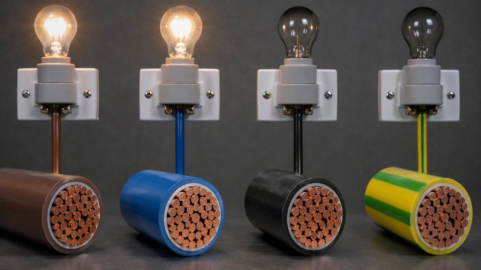
A live phase conductor and a dead one look exactly the same. Same color, same insulation condition, same diameter, same feel. This is not a minor caveat — it’s the core reason lockout/tagout procedures exist, and why IEC 60364 and every serious national installation code require proving dead with a calibrated voltage tester before any contact. Relying on color alone is a maintenance habit that injures people. Brown insulation means the intended function is phase; it tells you nothing about the present energized state.
Scenarios Where Cables Become Unexpectedly Energized
Back-feed from a generator is probably the most common surprise on industrial sites and in facilities with standby power. An operator isolates the utility supply, assumes the circuit is dead, and doesn’t realize a transfer switch has connected a generator on the load side. The cable is now live from the wrong direction.
Capacitive charge retention is less obvious but real. High-voltage cables — particularly those with appreciable capacitance per unit length, which climbs with cross-section and with XLPE dielectric construction — retain charge after disconnection. A 10 kV cable of modest length can hold enough stored energy to cause a serious arc. The discharge time depends on capacitance, leakage resistance, and whether a discharge resistor is applied.
Induced voltage in bundled or parallel cable runs is something plant electricians often underestimate. A de-energized cable running parallel to an energized one in the same tray can develop tens to over a hundred volts through electromagnetic induction, depending on the parallel run length, the energized cable’s current, and the separation distance. This isn’t a fault condition — it’s normal physics, and it will show up on a voltmeter as real voltage on a supposedly dead conductor.
Neutral Voltage Under Fault Conditions
The IEC 60364 earthing system classification — TN, TT, IT — directly affects how dangerous a neutral becomes when something goes wrong. In a TN-C system, the combined neutral and protective earth (PEN) conductor carries both return current and fault current. A high-impedance connection in that conductor doesn’t trip a breaker; it raises the voltage of every exposed metal part connected to it. In a TT system, a ground fault on the neutral can shift the touch voltage at equipment in ways that a local RCD may not respond to quickly enough. IT systems used in hospitals and offshore installations float the neutral entirely from earth, which limits fault current on the first fault but means the neutral sits at an indeterminate potential relative to earth at all times.
A neutral conductor in a properly functioning TN-S installation is always safe to touchFalse
Under ground fault conditions, broken neutral scenarios, or high neutral-to-earth impedance, a neutral conductor can reach dangerous touch voltages well above the 50 V AC threshold defined as hazardous in IEC 60364-4-41. Always verify dead before contact.
The practical takeaway: the physical state of a cable wire is never apparent from visual inspection, color code, or circuit position alone. It must be measured.
How to Safely Test Whether a Cable Wire Has Electricity Before Touching It
Never assume a cable is dead. That single habit — or the failure of it — accounts for a disproportionate share of electrical fatalities in industrial plants worldwide. The cable looks identical whether it’s carrying 400 V or nothing at all. Proper testing is not a formality; it’s the only way to know.
Choose the Right Tool for the Situation
Testing methods are not interchangeable. Use them in order of what the job demands.
Non-contact voltage tester (NCV) is the fastest field check and the right first step in most low- and medium-voltage situations. Hold it near the cable jacket; it detects the electric field without touching any conductor. Practical limit: NCV testers vary wildly in sensitivity. A cheap unit may miss a shielded or armored cable where the screen attenuates the field. Always use a tester rated for the voltage class of the installation — a domestic-grade NCV pen has no business near a 10 kV feeder.
Digital multimeter with probes gives you a quantitative reading. Set to the correct AC or DC voltage range before probing, not after. Measure phase-to-earth and phase-to-phase. This matters because a conductor can show 0 V phase-to-earth due to a broken neutral or a floating reference, while still sitting at a dangerous potential relative to another conductor. A multimeter reading demands you understand what you’re measuring against.
Clamp-on current meter confirms whether current is actually flowing through a conductor without breaking the circuit. Useful when you suspect a cable is live under load but can’t safely access the terminals. If you’re seeing 0 A on a cable that should be feeding a running machine, that’s its own problem — but at least you know it’s not going to arc when you touch it. Clamp meters also reveal induced currents in supposedly dead cables lying parallel to live runs, which is a scenario that catches people off guard more often than it should.
Insulation resistance tester (Megger-type) is for de-energized verification, not for proving a cable is dead. It applies a DC test voltage — typically 500 V to 5 kV depending on the cable rating — to check insulation integrity. On IEC 60502-compliant cables like those built to Jinda’s standard construction, healthy insulation resistance values run from hundreds of MΩ to several GΩ depending on cable length, temperature, and humidity. Use this after you’ve already confirmed the cable is dead by other means.
The Correct Sequence Before Touching a Dead Cable
First, isolate the source at the breaker, switch, or isolator — not just the local disconnect. Then apply lockout/tagout (LOTO) per IEC 60079 or OSHA 29 CFR 1910.147. One lock per worker, no exceptions. After isolation, prove your tester is working by checking it on a known live source before you test the suspect cable. Test the cable — all conductors, not just one. Then prove the tester again on the known live source afterward. This “prove-test-prove” sequence catches a dead battery or a failed instrument that would otherwise give you a false safe reading.
For medium- and high-voltage work (roughly above 1 kV), add earthing and short-circuiting of the cable ends using approved discharge equipment. Capacitively stored charge in a long MV cable is enough to kill.
Testing only one conductor of a multi-core cable and assuming the rest are also dead is a recognized cause of electrical accidents in industrial environments.True
Multi-core cables can have individual conductors sourced from different circuits or phases, meaning one conductor being de-energized provides no guarantee about adjacent conductors in the same sheath.
Mistakes That Get People Hurt
A tester with a dead or low battery may give no indication on a live conductor. Some technicians tap-test the tester’s own battery indicator and assume it’s fine — that’s not the same as proving it on a live source. Induced voltage is the other trap: a de-energized cable running parallel to live cables for any significant distance can show 50–150 V of induced AC, enough to confuse a reading and, in some cases, enough to be dangerous to touch depending on the source impedance. That reading is not always “safe”; it depends on what’s driving it.
Confusing a low-voltage reading with a safe reading is a subtler mistake. Fifty volts DC can be lethal under certain contact conditions. The threshold in most occupational safety standards is 50 V AC or 120 V DC as the boundary for “low voltage hazard,” but even below those figures, the risk is real in wet or conductive environments.
None of this changes based on who made the cable. Whether you’re working with Jinda’s LV power cable built to IEC 60502 or any other compliant product, the construction protects you during normal service — it does not protect you from an incorrectly tested installation. The insulation keeps current in; correct testing protocol is what keeps you safe before you work on it.
Cable Types and Their Electricity-Carrying Roles: Power, Control, and Signal Cables Compared
Not all cables carry electricity the same way. Voltage level, current magnitude, signal integrity, and environmental demands differ so much across cable categories that specifying the wrong type isn’t just a procurement mistake — it can mean nuisance trips, failed instrumentation, or a genuine safety hazard. Here’s how the main categories actually differ in practice.
Power Cables: Moving Real Energy
Low-voltage power cables rated 0.6/1 kV are the workhorses of most industrial and commercial installations. Conductor cross-sections run from 1.5 mm² for branch lighting circuits up to 400 mm² or 630 mm² for main feeders, carrying anywhere from roughly 15 A to well over 500 A depending on cross-section, installation method, and ambient temperature — those three variables together, not cross-section alone, set the real ampacity. XLPE insulation has largely displaced PVC at this rating because it tolerates higher continuous conductor temperatures (90°C versus 70°C), which directly affects how much current a given cross-section can carry without accelerating insulation aging.
Medium- and high-voltage cables — 6 kV, 10 kV, 35 kV, up to 110 kV and above — shift the design focus from conductor sizing toward insulation system engineering. At 110 kV, the insulation wall thickness and the geometry of the semi-conductive screens around the conductor and insulation matter far more than the conductor resistance. These cables transmit bulk power between substations or from generation points to distribution networks. Armored construction (steel wire armor or steel tape armor) protects against mechanical damage during direct burial or cable tray runs through industrial plants.
XLPE-insulated power cables manufactured to IEC 60502 can operate at continuous conductor temperatures up to 90°C, compared to 70°C for standard PVC-insulated cables at the same voltage rating.True
IEC 60502-1 and cable industry thermal ratings confirm these maximum continuous operating temperatures for XLPE and PVC insulation systems respectively; the difference directly affects derating calculations and ampacity tables.
Control Cables: Commands, Not Kilowatts
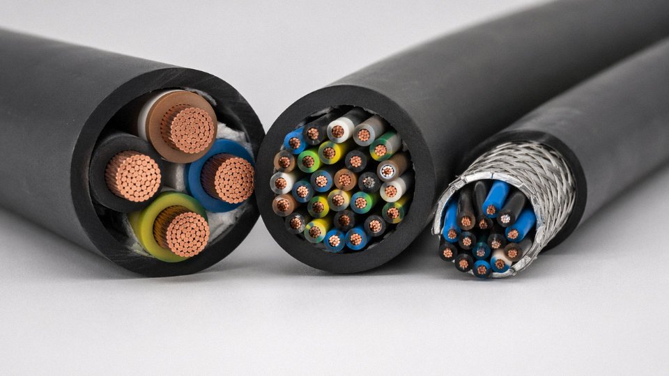
Control cables rated 450/750 V serve a completely different function. They carry the switching signals and command voltages between a motor control center and its contactors, between a PLC output card and a solenoid valve, or between a relay panel and field devices. Conductor sizes stay small — typically 0.75 mm² to 6 mm², most commonly 1.5 mm² or 2.5 mm² — because the currents involved are low, often just a few hundred milliamps for a relay coil or a pilot lamp circuit. Multi-core construction matters here: 4-core, 7-core, 12-core, up to 61-core cables are common, bundling many independent circuits in one run. In practice, a plant that tries to substitute a spare power cable core for a control circuit usually finds it works electrically, but the heavier conductor is stiff and awkward in a crowded terminal box, and it creates a traceability headache during maintenance.
Instrumentation and Signal Cables: Where Noise Is the Enemy
At the millivolt and milliamp level, the physics change again. A 4–20 mA process loop or a thermocouple extension cable isn’t particularly concerned with current capacity — a standard twisted pair can handle those signal currents without breaking a sweat. What it cannot handle without proper design is electromagnetic interference from nearby power cables, variable-frequency drives, or switchgear. Shielded twisted pairs with overall foil screens, individual pair screens, or both are standard. The shield must be grounded at one end only in most installations to avoid creating a ground loop that injects noise into the very signal you’re trying to measure. Getting that grounding practice wrong is surprisingly common, and it typically shows up as unexplained 50 Hz or 60 Hz ripple on an analog input, which the control system then faithfully misreads as a process fluctuation.
Specialty Cables: Electricity in Demanding Environments
Fire-resistant cables maintain circuit integrity long enough for emergency systems — evacuation lighting, fire pumps, smoke control fans — to keep operating during a fire. The electricity-carrying role is identical to a standard power cable, but the insulation system (typically mica tape combined with a halogen-free compound) is engineered to resist flame and maintain conductor separation under direct fire exposure for 90 minutes or more per IEC 60331. Explosion-proof and mining cables add further requirements around arc containment and jacket toughness. Submarine cables contend with hydrostatic pressure, moisture ingress, and the mechanical loads of cable laying operations, which drives multi-layer armor and specialized water-blocking compounds. Flexible trailing cables for mobile equipment — cranes, mining shovels, port machinery — carry full load current like a power cable but must survive continuous flexing, which means finely stranded conductors and flexible rubber or thermoplastic elastomer sheaths rather than rigid PVC.
Each of these categories is manufactured under specific IEC, BS, or customer-specified standards, and the right starting point for any procurement decision is matching the cable’s rated voltage, current capacity, and environmental classification to the actual installation conditions — not just ordering by conductor size alone.
Why Cable Insulation Fails and What Happens When Bare Conductor Is Exposed
Insulation doesn’t fail dramatically most of the time. It fails slowly, invisibly, over years — until one day the cable wire has electricity somewhere it absolutely shouldn’t, and you’re dealing with a ground fault, a fire, or worse.
Thermal Aging: The Most Common and Most Overlooked Cause
Every insulation material carries a continuous temperature rating. XLPE, the workhorse of modern medium-voltage cables, is rated for 90°C conductor temperature under continuous load. Push that to 105°C — which happens readily when a cable is undersized for its actual load, bundled too tightly in a conduit without adequate derating, or installed in an ambient that nobody re-evaluated after the plant expanded — and the cross-linked polymer network begins to degrade faster than its design life assumes. Not immediately catastrophic, but the molecular structure becomes brittle and microcracks form. A cable rated for 30 years of service can see insulation resistance drop significantly within 8–12 years under sustained thermal overload. PVC-insulated cables are even more sensitive; above roughly 75–80°C they begin to plasticize, meaning the plasticizers that keep the material flexible leach out, leaving the insulation hard and cracked.
Mechanical Damage, Rodents, and Chemical Attack
Abrasion is a plant-floor reality. Cables routed along cable trays near moving equipment, dragged across sharp tray edges during installation, or pinched under conduit fittings — these are routine sources of insulation thinning. A cable that passes spark testing at the factory can arrive at the installation site with compromised insulation after a rough pull-through. Rodent attack is genuinely common in food processing, agricultural, and warehouse environments; rats will chew through PVC sheath and insulation down to the conductor faster than most maintenance schedules catch it.
Chemical attack is subtler. Standard PVC sheath degrades in sustained contact with petroleum-based cutting oils, hydraulic fluid, and many industrial solvents. UV exposure matters too — standard sheath compounds break down with prolonged outdoor exposure, which is why direct-sun installations call for a UV-stabilized or HDPE outer sheath rather than standard PVC. Using the wrong sheath compound because it was cheaper or just happened to be in stock is the kind of procurement shortcut that creates problems two or three years down the line.
Moisture ingress typically happens at terminations and joints, not along the cable body. An improperly sealed cable gland on an outdoor junction box allows water to wick along the conductor strands by capillary action, sometimes traveling several meters into the cable run before showing up as a fault.
What Happens Electrically When Insulation Fails
Degraded insulation produces leakage current to ground — small at first, measurable with a Megger, but accelerating as the degradation worsens. In industrial systems, a full insulation breakdown between phases can drive fault currents in the range of 10–50 kA depending on system impedance and upstream protection. That level of fault energy doesn’t just trip a breaker; it produces arc flash with enough thermal energy to ignite cable sheath, nearby cable bundles, and cable tray coatings. Several industrial fires trace back to a single cable fault that propagated because adjacent cables had aged insulation and the tray was overloaded with combustible material.
A new medium-voltage cable should show insulation resistance in the hundreds of MΩ to GΩ range; readings below 1 MΩ per kV of rated voltage are generally treated as warning indicators requiring investigation.True
This threshold is consistent with industry practice and IEC guidance for insulation resistance assessment of power cables during commissioning and maintenance testing.
A reading below 1 MΩ per kV of rated voltage doesn’t necessarily mean the cable has failed outright, but it means you investigate before energizing. That’s the practical rule most commissioning engineers work from.
How Factory-Level Testing Catches Problems Before They Reach the Field
The place to catch insulation defects is before the cable ships, not after it’s buried in a tray or routed through conduit. At Jinda, every low-voltage cable run passes through spark testing at 4 kV — an electrode sparks along the moving insulated conductor, and any pinhole, thin spot, or contamination inclusion triggers an immediate alarm and rejection. For medium-voltage cables, partial discharge testing detects internal voids and treeing initiation sites that spark testing can’t see, because those defects don’t produce a direct short but will eventually fail under service voltage stress. Conductor resistance is verified against IEC 60228 class requirements, which matters because an undersized or poorly compacted conductor runs hotter than expected at rated current — feeding back into the thermal aging problem from the start.
The practical point is that insulation quality isn’t visible from the outside. Two cables can look identical in their outer sheath and have meaningfully different insulation wall consistency, void content, and long-term performance. Process control during extrusion and the testing protocols applied before dispatch are what separate cables that last from cables that become maintenance problems.
Grounding, Shielding, and Armor: The Parts of a Cable That Handle Electricity Under Fault Conditions
Most engineers who’ve worked with low-voltage systems for years encounter medium-voltage cable for the first time and immediately ask: what does the copper tape wrapped around the insulation actually do? Is it live? Should it be earthed? The confusion is understandable — these layers look passive but behave electrically in ways that can kill someone if the installation is done wrong.
The Cable Screen: Confining Fields, Not Just Carrying Current
In medium and high-voltage cables (roughly 6 kV and above, though some 3.3 kV designs include screening), the metallic screen — usually copper tape, copper wire, or a combination — serves a fundamentally different purpose than the conductor. Its primary job is to contain the electric field within the insulation layer, forcing the field to distribute radially and symmetrically. Without a screen, the electric field around an unscreened conductor can distort unpredictably depending on what’s near the cable — other cables, conduit walls, moisture — and that distortion accelerates insulation breakdown.
The screen also prevents capacitive coupling to adjacent cables, which matters a great deal in medium-voltage switchgear rooms where cables run in close parallel runs for significant distances. Under normal energized conditions, the screen carries only small capacitive charging currents — on a 33 kV cable, that might be anywhere from a few milliamps to tens of milliamps per kilometer depending on capacitance and frequency, nothing dramatic on its own. Under a ground fault, though, the screen becomes a fault current return path, and those currents can be substantial. This is why the screen must be solidly bonded to earth at the termination points; an ungrounded screen on a faulted cable will rise to a dangerous voltage potential relative to anything grounded nearby.
Armor: Mechanical Protection That Gets Electrically Complicated
Steel wire armor (SWA) and steel tape armor (STA) are primarily mechanical — protecting against dig-in, crushing, rodent damage, and the like. But steel is conductive, and armor forms a closed metallic path running the full length of the cable. That creates an induction problem on AC systems.
For three-core cables, the three phases are physically close enough that their magnetic fields largely cancel, and induced voltages in the armor are low. Bonding and earthing at both ends is standard practice and causes no meaningful circulating current. For single-core AC cables — common in large power installations where 240 mm² or 400 mm² conductors would be unwieldy in a three-core format — the armor surrounds a single phase conductor, and the asymmetric magnetic field induces a voltage along the armor’s entire length. Bond both ends to earth on a long single-core AC run, and you create a shorted secondary winding. Circulating currents in that loop can cause measurable heating in the armor itself, reducing the cable’s current-carrying capacity and, in extreme cases, degrading the outer sheath.
The practical rule: on single-core AC cables, earth the armor at one end only unless a cross-bonding scheme has been engineered.
Bonding Schemes on High-Voltage Metallic Sheaths
Lead-sheathed and corrugated aluminum-sheathed HV cables introduce another layer of deliberate engineering. Three schemes are used:
| Bonding Scheme | How It Works | When to Use It |
|---|---|---|
| Solid bonding | Sheath earthed and connected at both ends | Short cable lengths, three-core cables, DC systems |
| Single-point bonding | Earthed at one end only; voltage appears at the unearthed end | Medium-length single-core AC runs where induced voltage stays below ~65 V |
| Cross-bonding | Sheaths transposed and bonded in minor sections across a major section | Long single-core AC runs; minimizes net sheath voltage and circulating current simultaneously |
Cross-bonding is the most engineering-intensive option. It requires sectionalizing joints, careful sheath voltage limiter (SVL) selection, and precise transposition — but on a 1–2 km single-core 132 kV installation, it’s often the only scheme that keeps sheath losses within acceptable limits.
An ungrounded steel wire armor on a faulted cable can rise to lethal touch voltage.True
If the armor is not bonded to the earthing system and a fault energizes it, there is no low-impedance return path — the armor floats at a voltage determined by the fault current and the impedance of the path through the fault to earth. Depending on fault level and cable length, this can easily exceed 50 V AC and reach hundreds of volts, presenting a genuine electrocution risk to anyone touching the cable outer surface.
What This Means at the Termination Point
Every HV or MV cable termination is where grounding intent meets physical reality, and it’s where most of the mistakes happen. A screen or armor that looks terminated — the wire bent back and tucked under a gland — but isn’t actually making contact with the earthing conductor is effectively floating. In practice, verify continuity from armor/screen to the earth bar with a low-resistance ohmmeter before energizing. A reading above a few ohms on a properly bonded termination warrants investigation; an open circuit is a serious problem that needs to be fixed before the cable goes live.
Jinda’s technical support team regularly advises project engineers on screen and armor termination requirements during cable specification and before installation commences — because getting this right at the design stage is far easier than diagnosing unexplained sheath heating or a fault-induced touch voltage incident six months into commissioning.
Selecting the Right Cable to Safely Carry the Required Electricity: Key Sizing Parameters
Getting the cable selection wrong costs money in one of two ways: oversize it and you’ve wasted copper; undersize it and you’re looking at nuisance tripping, accelerated insulation aging, or in the worst case, a fire. Neither outcome is acceptable. The four steps below are how experienced engineers work through a specification — not a checklist to rush, but a sequence where each step depends on the one before it.
Step 1 — Determine Current-Carrying Capacity (Ampacity)
Start with your design load current, then work backward through the derating factors. IEC 60287 sets reference conditions at 30°C ambient air and 20°C ground temperature. If your installation is in a Middle Eastern facility where ambient air regularly hits 45–50°C, or a cable tray packed with a dozen circuits, the nameplate ampacity on a data sheet means very little without corrections applied.
Grouping is the factor engineers most often underestimate. A single 95 mm² copper XLPE cable in open air might be rated somewhere around 250–290 A depending on installation method; bundle four of those cables in a conduit and you’re applying a grouping factor that can drop effective ampacity by 30–40%. Depth of burial matters for ground-laid cables — deeper runs mean better soil heat dissipation in theory, but poorly compacted backfill or dry sandy soil with high thermal resistivity (anywhere from 0.5 to 3.0 K·m/W depending on moisture content and soil type) can flip that assumption entirely. Always get a soil thermal resistivity measurement on large projects rather than assuming a textbook value.
Step 2 — Check Voltage Drop
For final circuits, IEC 60364-5-52 sets a typical maximum of 3–5% voltage drop. The working formula is:
ΔV = (ρ × L × I) / A
where ρ is conductor resistivity (roughly 1.72 × 10⁻⁸ Ω·m for copper at 20°C, about 2.82 × 10⁻⁸ Ω·m for aluminum), L is one-way circuit length in meters, I is current in amperes, and A is cross-section in m². On long runs — say, a 200 m feeder to a remote pump in a water treatment plant — voltage drop frequently controls the conductor size selection, not ampacity. In those cases you end up upsizing the cable purely to keep the motor terminal voltage within tolerance, which is completely legitimate engineering but needs to be recognized early rather than discovered during commissioning.
Step 3 — Verify Short-Circuit Rating
This step gets skipped more than it should. The conductor has to survive the prospective fault current for however long it takes the protective device to clear the fault. The adiabatic equation:
S = (I × √t) / k
gives minimum cross-section S in mm², where I is fault current in amperes, t is clearing time in seconds, and k is a material constant — 115 for PVC-insulated copper, 143 for XLPE-insulated copper. A fast-acting fuse that clears in 0.1 s is far more forgiving than a slow overcurrent relay set with a 1-second delay. In industrial substations with prospective fault currents of 25–50 kA, this calculation can easily mandate a larger conductor than either ampacity or voltage drop would require.
The adiabatic constant k = 143 applies to XLPE-insulated copper conductors per IEC 60364-5-54 and IEC 60949.True
XLPE insulation tolerates a higher maximum conductor temperature under short-circuit conditions than PVC, which is why its k value is higher — this allows slightly smaller cross-sections for equivalent fault duty.
Step 4 — Match Cable Type to Environment
Ampacity, voltage drop, and fault rating tell you the size. The environment tells you the construction. Direct burial in soil needs armored XLPE — typically SWA (steel wire armored) or STA (steel tape armored) construction — to handle mechanical stress during backfilling and long-term ground movement. Hazardous areas (Zone 1/Zone 2 per IEC 60079) require certified flame-retardant or in some cases explosion-proof sheathing, and the certification paperwork needs to be traceable, not just claimed on a spec sheet. Marine and offshore installations add oil resistance and stricter flame-retardant requirements to the sheathing, since cable runs near machinery may contact hydraulic fluid or fuel.
In practice, the certification trail matters as much as the physical spec, especially for export projects where customs clearance or local grid-operator acceptance depends on seeing CCC, CE, or SGS documentation. Specifying the right construction but sourcing a cable that can’t produce credible third-party test reports is a procurement failure that shows up at the worst possible moment — during commissioning, not before.
Frequently Asked Questions About Whether Cable Wire Has Electricity
These are the questions that come up repeatedly — on job sites, in procurement emails, and in safety briefings. Short answers exist, but the nuance matters more than the headline response.
Can a cable wire have electricity even when the switch is off?
Yes, and this catches people out more often than it should. If the switch interrupts the neutral conductor rather than the live, the cable feeding the load stays energized at line voltage even with the switch open. Two-way switching configurations — common in stairwells and corridors — add another layer of complexity: depending on switch position, the “strapper” cables between the two switches may be live regardless of whether the light is on or off. The only safe assumption is that any cable in a switched circuit is potentially live until you’ve tested it with a calibrated non-contact voltage tester or a properly rated multimeter. Flipping a switch at the panel is not the same as isolation.
A cable feeding a load can remain at full line voltage even when the connected switch is in the off position.True
This occurs when the switch is wired into the neutral conductor, or in multi-way switching arrangements where intermediate cables may remain at line potential regardless of switch state. IEC wiring practice requires switching on the live conductor, but older or non-compliant installations frequently violate this.
Does a cable carry electricity if it is not connected to anything?
No current flows through a completely isolated cable — there is no closed circuit, no path for electrons, nothing happens. That said, cables that were recently disconnected from medium- or high-voltage sources (roughly 6 kV and above) can retain a residual capacitive charge for a short period, sometimes tens of seconds, long enough to deliver a serious shock if you grab the conductor bare-handed. Standard practice on MV and HV work is to apply shorting-and-earthing clamps before touching anything. For low-voltage cables (0.6/1 kV class), this is less of a practical concern, but the discipline of treating disconnected cables as suspect is worth keeping.
Is the outer sheath of a cable electrified?
Under normal conditions, no. The outer sheath is either an insulating polymer layer (PVC, LSZH, HDPE) or a mechanical protection layer, and it is designed to be at ground potential or simply isolated from current. The problem arises when inner insulation has degraded — thermal damage, rodent attack, water ingress, abrasion against a conduit edge — and the cable is still energized. In that scenario the sheath, and any metallic armor beneath it, can become live. Armored cables where the SWA layer has not been properly bonded and earthed are a specific hazard. Treat every cable as potentially dangerous until you have confirmed otherwise with instrumentation.
How do I know if a cable is rated for my voltage?
Read the print legend on the outer sheath. A properly manufactured cable will carry continuous print-marking at regular intervals showing the rated voltage (for example, 0.6/1 kV), the applicable standard (IEC 60502-1 for most power cables), conductor material (Cu or Al), cross-section in mm², and the manufacturer’s identification. If any of this is missing or illegible, that is itself a quality flag. Jinda cables carry full sheath marking per IEC requirements, which makes site verification straightforward during goods receipt inspection.
What is the difference between a cable and a wire — do both carry electricity?
A wire is a single conductor, insulated or bare. A cable is an assembly — one or more insulated conductors, plus bedding, shielding where required, armor, and an outer sheath. Both carry current through the conductor material. The distinction matters for installation: a bare wire or even a single-core insulated wire is not appropriate for most building or industrial wiring without additional mechanical and electrical protection. When a procurement spec says “cable,” it means the full layered assembly, and substituting single-core wire creates real compliance and safety problems.
Can I use a low-voltage cable on a higher-voltage circuit?
No. This is not a gray area. A cable’s insulation is engineered to withstand a specific maximum voltage continuously, with margins built in per the relevant standard. Push beyond that rating and the insulation may not fail immediately — it degrades, partial discharge starts eating it from the inside, and eventually you get a breakdown event. Depending on the installation that means arc flash, fire, or electrocution. The rule is simple: cable voltage rating must meet or exceed system voltage. If you are unsure whether your procurement spec matches the actual circuit voltage in a specific installation, Jinda’s technical team can review the application and confirm the correct product — that conversation is faster than an incident investigation.
Why Cable Quality Directly Determines How Safely and Reliably Electricity Is Carried Over the Cable’s Lifetime
Every technical point covered in this article — conductor resistivity, insulation integrity, fault current paths, proper sizing — ultimately collapses into a single practical question: did the cable you installed actually meet the specification printed on its jacket? Because if it didn’t, everything else is academic.
The Quality Chain That Determines Long-Term Electrical Performance
Start with the conductor. IEC 60228 sets minimum purity at 99.9% electrolytic copper for Class 1 and Class 2 conductors. That matters because copper resistivity at 20°C is roughly 1.72 × 10⁻⁸ Ω·m — but only at that purity. Drop to 99.5% or lower through recycled scrap blending, and resistivity climbs, heat generation rises under load, and the cable runs hotter than its insulation system was designed to tolerate. Over a 30–40 year service life, that differential is the difference between a cable that retires gracefully and one that triggers a fire in year 12.
Insulation wall thickness is equally unforgiving. IEC 60502 allows a tolerance of ±10% of nominal wall thickness — not more. A cable with consistently thin insulation on one side (common when extrusion dies are worn or process control is loose) has locally reduced dielectric strength right where partial discharge initiates. It won’t fail the day you install it. It fails during a voltage transient three years in, or when operating temperature is elevated during a summer peak load period. Seasonal thermal cycling accelerates the damage every year.
Concentric stranding geometry and sheath adhesion are less discussed but equally real. Poor stranding means uneven current distribution across conductor wires, localized heating at contact points, and accelerated oxidation. A sheath that doesn’t adhere consistently to the bedding layer beneath it allows moisture ingress at termination points — and once water tracks along the cable interior, you have a slow-motion insulation failure that’s nearly impossible to diagnose until something trips.
What Substandard Cable Looks Like in Practice
Undersized conductors are the most widespread quality fraud in low-cost cable imports. Measured cross-sections 20–30% below nominal are not rare — they’re documented repeatedly in third-party import audits. A cable labeled 16 mm² carrying only 11–13 mm² of actual copper has proportionally higher resistance, generates more heat per ampere, and forces the insulation to work at temperatures above its rated ceiling from day one. That cable starts as a passive conductor and becomes an active fire hazard.
Undersized conductors in low-cost cable imports commonly measure 20–30% below the nominal cross-section stated on the cable jacket.True
This finding is documented in multiple independent third-party cable audit reports and IEC-accredited laboratory tests comparing imported cables against their labeled specifications. The discrepancy directly increases conductor resistance and operating temperature, accelerating insulation degradation.
The failure mode isn’t always dramatic. Usually it’s a slow thermal degradation — insulation that gets brittle, develops micro-cracks, then fails at a terminal block or a bend point. By the time a circuit breaker trips, you’ve already got carbonized insulation and potentially compromised adjacent cables in the same tray.
Jinda’s Manufacturing Position
Shandong Jinda Special Cable Group has been manufacturing and exporting cables since 1987 — long enough to have supplied cables that are still in service, which is the only honest proof of quality. Five production bases across Shandong, China, cover roughly 470,000 m² of factory floor. Over 1,000 specialized employees handle everything in-house: conductor drawing, stranding, insulation extrusion, armoring, and final testing. The quality laboratory isn’t a separate building you visit for audits — it’s integrated into the production process, with routine conductor cross-section verification, insulation thickness measurement, and spark testing on every drum.
Export experience across more than 50 countries means Jinda’s engineering team has dealt with IEC, BS, NFC, and project-specific specifications across industrial, infrastructure, marine, and utility applications. That breadth matters when you’re specifying a non-standard voltage rating or a custom sheath compound for a humid tropical environment and need a supplier who can actually produce it consistently at volume — not just quote it.
For bulk procurement, long-term supply agreements, custom specifications, or factory audit arrangements, Jinda’s international sales team is the right starting point. If you’re an engineer who’s read this far, you already understand what to ask for. Contact Jinda for technical consultation, product samples, and competitive pricing on both standard and custom cable configurations — because cables that carry electricity reliably for 30+ years don’t happen by accident.