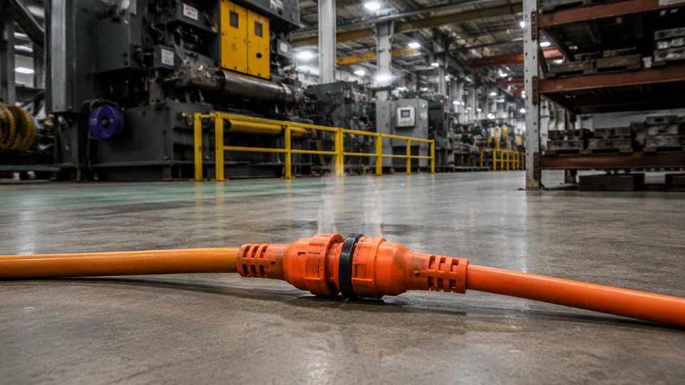
You’ve got a machine running at the end of a long bay, the nearest outlet is forty feet away, and someone has already plugged one extension cord into another to reach it. It works — right up until it doesn’t. The resistance builds, the connectors heat up, the insulation softens, and somewhere in that chain you get a fault that trips a breaker at best or ignites a fire at worst. In a production environment, that’s unplanned downtime, damaged equipment, and a potential OSHA citation stacked on top of each other.
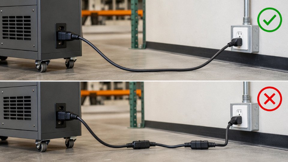
No, it is not safe to plug a power cord into a power cord. Daisy-chaining extension cords creates cumulative voltage drop, increases resistance at each connection point, and exceeds the ampacity limits the individual cords were rated for. NEC Article 400, IEC 60884-1, and OSHA 29 CFR 1910.305(g) all prohibit this practice. The correct fix is a single properly rated cord, a relocated outlet, or a temporary power distribution unit sized for the actual load.
What surprises most people — including some experienced electricians — is how quickly the physics turns against you even when the connected load looks modest on paper. A pair of 16 AWG cords carrying a 12 A load doesn’t just “work a little less well.” It compounds heat, compounds drop, and introduces a failure point right at the plug-to-socket interface that no breaker upstream is necessarily sized to catch in time.
The Electrical Physics Behind Daisy-Chaining: Resistance, Voltage Drop, and Heat Buildup
Series resistance is the starting point, and it’s brutally simple. Every conductor has resistance — a function of material, cross-sectional area, and length. For copper, 16 AWG runs roughly 4.0–4.2 mΩ per foot (both conductors combined), while 12 AWG drops that to about 1.9–2.0 mΩ per foot. Plug two 25-foot cords together and you’ve stacked two full conductor lengths in series. The total resistance isn’t some weighted average — it’s additive: R_total = R₁ + R₂ + R_connector_joint. That connector joint term is the one most engineers initially underestimate.
At 15 A through two 25-foot, 16 AWG cords, the I²R loss in the conductors alone works out to roughly 3–5 V of drop per cord segment, depending on the actual conductor quality (cheaper imported cords frequently measure at the high end of that AWG tolerance band). Stack both cords and you’re looking at 6–10 V of total drop on a 120 V circuit — that’s 5–8% before you’ve even accounted for the junction. NEMA and IEC equipment tolerances typically allow ±10% voltage variation, so you’re already chewing through that margin with nothing but two cheap extension cords and a moderate load.
Connecting two 25-foot 16 AWG extension cords in series at a 15 A load can produce 6–10 V of voltage drop on a standard 120 V circuit.True
Calculated from conductor resistance of approximately 4.0–4.2 mΩ per foot for 16 AWG (both conductors), with 15 A load across 50 total feet of conductor. I²R losses accumulate additively across both cord segments, consistent with NEC voltage drop calculation methods.
For motors — a small compressor, a bench grinder, anything with a startup inrush — this matters more than people realize. A motor that’s rated for 115 V minimum will try to compensate for low voltage by drawing more current, which heats the windings, which shortens the motor’s life in ways that don’t show up immediately. The motor doesn’t fail the day you daisy-chain the cord. It fails eight months later and nobody connects the two events.
Now to the connector joint itself. This is where the physics gets genuinely dangerous. The female receptacle end of the first cord mates with the male plug of the second, and that mechanical interface — even when new — introduces contact resistance. Over time, with any movement, vibration, or repeated connect/disconnect cycles, the blade contacts oxidize and the fit loosens. Resistance at a degraded joint can reach several hundred milliohms, orders of magnitude higher than the cord’s own conductor resistance. At 15 A, even 100 mΩ of joint resistance dissipates 22.5 W in a space roughly the size of your thumb. That heat has nowhere to go efficiently — the plastic housing acts as an insulator, not a heat sink.
Common extension cord insulation tells the rest of the story. Standard PVC jacket material is typically rated for continuous service up to about 60–75 °C. TPE and rubber compounds do better, usually 90–105 °C, and you’ll find those on better-grade outdoor or industrial cords. The problem is that sustained overloading at a chained junction can push local temperatures well past 75 °C — at the contact surface, not the outer jacket — long before the upstream 15 A breaker sees anything worth tripping over. Breakers protect conductors from sustained overcurrent; they don’t protect a marginal mechanical joint from its own resistance heat.
Load diversity factor compounds everything. In practice, people don’t plug one appliance into a daisy-chained cord. They plug a power strip into the second cord’s end and run three or four devices. The assumed diversity — the idea that not all loads will peak simultaneously — evaporates in real use. A space heater, a laptop charger, and a monitor don’t stagger their demand politely. Peak simultaneous draw on a typical daisy-chained setup routinely exceeds the rated ampacity of the weakest cord in the chain, which is almost always the older, lighter-gauge one that happened to be lying around.
Applicable Electrical Codes and Standards That Prohibit or Restrict Cord-to-Cord Connection
If you work in a regulated environment — a manufacturing plant, a construction site, a commercial building — the question of whether daisy-chaining extension cords is “safe” isn’t purely a physics question. It’s already been answered by code bodies, and the answer is no. Here’s the authoritative reference map you need when a safety audit comes around or an insurance adjuster starts asking questions.
NEC Article 400.12 and the Substitute-Wiring Prohibition
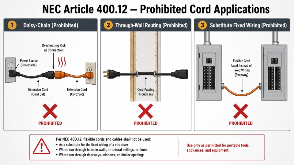
The National Electrical Code, Article 400.12, lists specific prohibited applications for flexible cords and cables. Using a cord as a substitute for fixed wiring is explicitly banned. So is routing cords through walls, ceilings, floors, or similar structural elements — conditions that a daisy-chain almost inevitably encourages once someone runs out of reach and starts improvising. The underlying logic is that flexible cords are designed as temporary, attended connections, not as part of a circuit’s permanent current-carrying infrastructure. When you plug one cord into another, you’ve created an unprotected series extension that the original overcurrent device was never sized to supervise correctly. In practice, the outlet circuit breaker may be 15 A or 20 A, but the weakest cord in the chain could be rated for 10 A on a 16 AWG conductor. The breaker won’t see a problem until it’s far too late.
OSHA 29 CFR 1910.305(g)(1)(iv): The Workplace Ban with Teeth
OSHA’s general industry standard is blunter than the NEC. 29 CFR 1910.305(g)(1)(iv) explicitly prohibits using extension cords connected to one another — the daisy-chain — in workplace settings. This isn’t a gray area subject to interpretation. Violations are cited under OSHA’s electrical standards, and willful or repeat violations can reach $15,000–$156,000 per citation depending on severity classification and whether the employer has prior history. Serious violations typically land in the $1,000–$15,000 range. OSHA inspectors regularly photograph cord configurations during walkthroughs; a daisy-chain on a machine room floor is low-hanging fruit for a citation.
OSHA 29 CFR 1910.305(g)(1)(iv) explicitly prohibits connecting extension cords together in general industry workplacesTrue
OSHA's general industry electrical standard directly addresses this practice under flexible cords and cables, prohibiting cord-to-cord connections as a wiring method in occupational settings.
IEC 60884-1, IEC 60245, and IEC 60227: The International Framework
Under IEC 60884-1 — the standard governing plugs and socket-outlets for household and similar purposes — socket-outlets are tested and rated for specific connection configurations. Plugging one flexible cord assembly into another creates a connection point that falls outside the tested configuration envelope. IEC 60245 and IEC 60227 govern the flexible cord constructions themselves, and neither standard contemplates series-connection as an acceptable installation method. European national standards bodies (DIN VDE, NF C, and others) have adopted these frameworks largely as-written, so the restriction applies across most of the EU and associated markets, not just in North America.
BS 7671 Regulation 526.1 and the UK Position
The UK’s 18th Edition Wiring Regulations, BS 7671, addresses this through Regulation 526.1, which requires that every electrical connection be mechanically and electrically sound, adequately protected against mechanical damage, and accessible for inspection. An improvised cord-to-cord joint satisfies none of those criteria reliably. The connection point sits on the floor, gets kicked, flexes under load, and is typically inaccessible without moving equipment. UK insurance loss adjusters are well aware of this regulation, and it surfaces routinely in post-incident investigations.
What Insurance Actually Does With This
Speaking of insurance: if a fire investigation reveals that daisy-chained cords contributed to the loss, most commercial property underwriters treat it as evidence of a known code violation in an unacceptable installation — and deny or substantially reduce the claim. Residential policies handle it similarly. The denial language typically cites either the insured’s failure to maintain premises to applicable code or an exclusion for damage caused by improper electrical installation. Practically speaking, that means a warehouse fire that started at a cord-to-cord connection, even if the primary cause was a separate equipment fault, can leave a facility owner absorbing the full loss.
Construction and Industrial Sites: Stricter Still
NFPA 70E, which governs electrical safety in the workplace with a focus on arc flash and shock hazards, and IEC 60364-7-704, which covers construction sites specifically, both impose requirements beyond the base NEC or IEC 60364-1 framework. These include mandatory GFCI protection for all temporary cords on construction sites, formal cord inspection programs (often requiring visual inspection before each shift), and documentation trails. On a site operating under NFPA 70E, a daisy-chained cord isn’t just a code violation — it’s a hazard that should trigger an immediate corrective work order under the facility’s electrical safety program. In my experience, the plants that take 70E seriously are the ones that have already had an incident. The others tend to find out the hard way.
Real Failure Modes: Overheating, Arc Faults, Ground Continuity Loss, and Mechanical Damage
Understanding why cord-to-cord connections fail requires looking at each mechanism separately — because they don’t all fail the same way, on the same timeline, or with the same warning signs. Some announce themselves with a burning smell. Others stay completely silent until there’s a fire or a person gets shocked.
Overheating at the Joint
The female receptacle end of an extension cord — the outlet end — is designed and tested for a specific range of contact resistance, typically under 0.5 mΩ when new and properly mated with a compatible plug. That matters because even a modest contact resistance increase causes I²R heating that grows with load current squared. When you plug a second cord’s male plug into it, you’re introducing variables the original designer never accounted for: a plug that may be slightly oxidized, a blade that’s been bent from previous use, or simply a physical fit that’s just loose enough to generate intermittent contact.
At 15 A continuous load, a joint with even 10–15 mΩ of elevated contact resistance can generate enough localized heat to soften the nylon or polypropylene receptacle housing — usually within an hour or two of sustained use. The upstream breaker won’t see this. The current is within spec; the breaker is happy. The heat is entirely localized at the connection point, invisible to any overcurrent protection in the circuit. By the time the housing melts far enough for arcing to begin, you’ve already got a fire precursor sitting on the floor.
Arc Fault Propagation
A loose plug-to-receptacle connection doesn’t just overheat — it arcs. Series arc faults, which is exactly what an intermittent plug-to-socket connection produces, generate high-frequency transient current signatures that a standard thermal-magnetic breaker cannot distinguish from normal load current. The arc energy per half-cycle is low enough that the breaker never trips, but sustained arcing at even 10–30 W can ignite cord insulation or nearby combustibles within the joint area.
Arc fault circuit interrupters (AFCIs) exist specifically to catch this failure mode. The problem is that most industrial installations built before roughly 2014, and the overwhelming majority of construction site temporary power setups, have no AFCI protection at all. Even in newer residential construction where AFCIs are NEC-required for bedroom circuits, the garage circuits or workshop drops feeding a daisy chain usually aren’t covered. So in practice, the arc fault protection that could catch this failure simply isn’t there in the environments where cord chaining happens most.
Standard circuit breakers cannot detect series arc faults generated by a loose cord-to-cord connection.True
Thermal-magnetic breakers respond to sustained overcurrent or short-circuit current. Series arc faults produce intermittent, low-energy arcing that doesn't exceed the breaker's trip threshold, making them invisible to conventional overcurrent protection. AFCI devices are specifically engineered to detect the high-frequency signature of arc faults.
Ground Continuity Degradation
Every cord joint is a potential break in the equipment grounding conductor. The ground blade connection inside a typical household-grade receptacle relies on spring-loaded contacts that can corrode, loosen, or fail mechanically under repeated insertion cycles. Chain two or three cords together and you’ve multiplied that failure probability accordingly. If the grounding conductor in the final cord section is open — even just resistively degraded to several ohms — a ground fault on the connected tool or appliance can’t return enough current to trip the breaker. The tool’s metal enclosure sits at a hazardous voltage. Someone touches it and the ground fault path runs through them instead of the conductor.
This is particularly insidious on construction sites, where cords take physical abuse daily and ground blade contacts in the intermediate receptacle get contaminated with concrete dust, moisture, and general site grime.
Mechanical Stress and Insulation Damage
Cords flex. The joint between a plugged-in cord and the next one in the chain is a stress concentration point — two cord jackets pulling in potentially different directions, with no strain relief designed for that configuration. Run that joint under a door, across a forklift aisle, or just let foot traffic walk over it repeatedly, and the insulation at that bend cracks. Usually the jacket goes first, then the conductor insulation. You end up with exposed conductors at a point that also happens to be a high-resistance, heat-generating connection.
Daisy-chaining doubles the number of these vulnerable points per run. Triple a chain, and you have at least four or five potential stress fracture zones, any one of which can initiate a fault.
The Construction Site Pattern
The failure sequence seen repeatedly in construction site fire investigations goes like this: a 14 AWG cord rated at 15 A is plugged into another 14 AWG cord to reach a saw or compressor drawing 18–20 A. The joint heats progressively. The cord insulation softens, then chars, then ignites — usually somewhere between 2 and 4 hours into continuous operation on a warm day when ambient temperature is already pushing the cord’s thermal rating. The fire starts low, in combustible debris that accumulates around cord runs. By the time it’s visible, it’s structural.
That sequence isn’t theoretical. It’s the pattern that makes temporary wiring one of the more consistent ignition sources in construction fire statistics.
When Industry Professionals Temporarily Need Extended Reach: Compliant Workarounds
The need is real. A machine gets repositioned six feet further from the wall outlet. A trade show booth needs power across a wide floor plan. A home office grows a third monitor and a docking station. None of these situations actually require daisy-chaining cords — they just feel like they do, usually because the right solution wasn’t planned for ahead of time.
Specify a Single Cord, Sized Correctly From the Start
The most reliable fix is also the least exciting: source one cord of the correct length and gauge before the job starts. NEC Table 400.5(A)(1) gives ampacity ratings for flexible cords by conductor size — 16 AWG handles up to 13 A, 14 AWG up to 15 A, 12 AWG up to 20 A in typical hard-usage applications. The length matters because voltage drop compounds over distance. A rough working rule: budget for a 3–5% maximum drop under full load, and for runs beyond 50 ft at loads above 10 A, step up one AWG size over what the ampacity table alone would suggest.
Measure the actual routing path, not the straight-line distance. Cable routed around doorframes, through conduit sleeves, or coiled on a reel runs longer than it looks on a floor plan — sometimes 20–30% longer. Get that number right before ordering, because a cord that’s six inches short will almost always end up connected to another cord.
Power Distribution Units and Temporary Power Assemblies
For job sites, machine shops, or any situation where multiple tools need power at a single work area, a single heavy-duty cord feeding a fused PDU is almost always the correct answer. One 12 AWG cord rated for the full anticipated load runs from a hardwired outlet or panel to a PDU with its own overcurrent protection. Each branch then carries only its own load. The math works. The protection is built in. Compare that to two 16 AWG cords chained together feeding a six-outlet strip — you’ve created a path where the upstream cord has no idea what the downstream devices are drawing.
Industrial PDUs vary widely; specify one rated for the environment (dusty? wet? high-vibration?) and verify it carries a UL 1363 or equivalent listing.
Spider Boxes on Construction Sites
Temporary power on construction sites falls under NEC Article 590, which explicitly anticipates the need for multi-outlet temporary distribution. Spider boxes — sometimes called temporary power centers or construction distribution boxes — are designed precisely for this. A single feeder from a generator or panel feeds the box, which provides fused or breaker-protected branch circuits at each outlet. NFPA 70E further requires GFCI protection for all 15 A and 20 A receptacle outlets on construction sites.
Spider boxes used under NEC Article 590 provide a code-compliant alternative to daisy-chaining extension cords on construction sitesTrue
NEC Article 590 specifically governs temporary installations and permits multi-outlet temporary power assemblies fed by a single properly rated feeder, satisfying both overcurrent protection and ground continuity requirements that cord-to-cord connections cannot reliably provide.
The Home Office Situation
A surge-protected, UL-listed power strip plugged into a single extension cord of adequate gauge is generally acceptable for light home-office loads — a laptop, monitor, and phone charger drawing maybe 4–6 A combined. The cord needs to be rated for the full load, kept uncoiled, and not run under rugs or through walls. That last point matters more than people think; a cord pinched under a desk leg for three years is a different risk profile than one lying flat and inspected occasionally.
When the circuit is already loaded near capacity, or the user is adding high-draw equipment — space heaters, laser printers, desktop workstations — the right call is a licensed electrician installing a dedicated outlet or additional circuit. Power strips do not create capacity; they redistribute it.
Cord Reels With Thermal Cutouts
For workshops and garages where extended reach is a recurring need, a UL 817-listed cord reel with an integrated thermal cutout is worth the upfront cost — typically somewhere in the $40–$120 range depending on capacity and cable length. The thermal cutout is the key feature: if the reel is left partially wound under load, resistance and heat build up in the coil, and the cutout interrupts the circuit before the insulation degrades. Using a reel without one, or bypassing it, removes that protection. In practice, a lot of shop fires start with an old cord reel that someone assumed was fine because it had worked for years.
Keep the reel fully extended under any load above roughly 50% of its rated ampacity. Partially coiled cord acts as an inductor and a heat trap simultaneously.
Matching Plug and Receptacle Ratings
This seems obvious until it isn’t. A NEMA 5-15 plug — the standard 15 A, two-parallel-blade configuration — will physically insert into a NEMA 5-20 receptacle, which has a T-shaped slot to accept both 15 A and 20 A plugs. The problem arises in the other direction: a 15 A-rated extension cord should never be used to feed a power strip or PDU with a 20 A receptacle configuration, because the downstream device may draw current the upstream cord cannot safely carry. The plug fits; the cord does not have the ampacity. That mismatch is where insulation gets hot and nobody notices until smoke appears.
Size the cord to the receptacle, not just to the expected load. The receptacle rating represents a potential, not a guarantee of what will actually be plugged in downstream.
How to Select the Right Flexible Cable Specification for Your Actual Load and Environment
Getting the specification right the first time eliminates the temptation to daisy-chain entirely. Most improvised cord connections happen because the cable already installed is too short, undersized, or wrong for the environment — problems that a proper specification review would have prevented at the procurement stage.
Conductor Sizing: Start With the Actual Load, Not a Guess
The calculation is straightforward: divide total connected load in watts by the supply voltage to get current in amperes. A 2,400 W load on a 120 V circuit draws 20 A; the same load on 240 V draws only 10 A. That difference matters enormously for conductor cross-section.
For continuous loads — anything running longer than three hours, which covers most industrial equipment — apply a 125% safety factor per NEC 210.19(A) logic. So that 20 A continuous load now requires a conductor rated for at least 25 A. From there, consult NEC Table 310.15 or IEC 60228 ampacity tables: 25 A continuous typically lands you at 10 AWG (roughly 5.26 mm²) for copper, depending on insulation temperature rating and installation method. Drop down to 12 AWG (3.31 mm²) and you are already marginal for sustained loads even before accounting for derating.
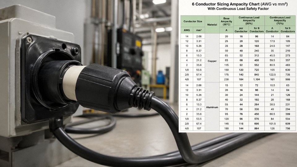
One thing procurement teams frequently overlook: flexible cord ampacity tables are not identical to fixed-wiring tables. Cords bundled together or coiled on a reel derate significantly — a coiled 12 AWG extension cord carrying 15 A can reach jacket temperatures high enough to accelerate insulation aging within an hour.
Insulation and Jacket: Match the Chemistry to the Environment
PVC jacket (H05VV-F being the typical IEC designation) is fine for indoor, dry, relatively benign environments. It is cheap, widely available, and perfectly adequate in an office or light-assembly setting. Put it outdoors in UV exposure or near oils, and you will see cracking within a season or two in hotter climates — in my experience, faster than most maintenance schedules catch it.
For outdoor and general industrial use, specify rubber-jacketed cord: SOOW or its IEC near-equivalent H07RN-F. The “W” in SOOW denotes weather and water resistance; the second “O” indicates oil-resistant outer jacket. H07RN-F uses natural or synthetic rubber and is rated for harsher mechanical abuse. Where chemical splash is a real risk — near solvents, cutting fluids, or cleaning agents — TPU or TPE jackets hold up considerably better than rubber, though they cost more and are less universally stocked.
Silicone-jacketed flexible cable is a different category. Specified for sustained temperatures above roughly 90–150 °C (depending on compound grade), it sees use near ovens, furnaces, and certain motor applications. It is softer and more tear-prone than rubber, so routing path matters.
Understanding Cord Type Designations
The SO/SOOW/SJOOW system is worth decoding rather than just copying a designation from a previous project. “S” means hard-service cord, rated 600 V. “SJ” is junior hard-service, rated 300 V — adequate for many portable tools but not suitable where full 600 V insulation is required. The “O” suffixes indicate oil resistance, and “W” adds outdoor suitability. Mixing these up in a procurement spec is a routine mistake that surfaces during an inspection or, worse, a failure.
SOOW flexible cord is rated for 600 V service with both oil-resistant inner and outer jackets, making it suitable for outdoor and industrial environments where SJ-series cord is not.True
Per UL Standard 62 and NEC Article 400 Table 400.4, SOOW carries a 600 V rating with dual oil-resistant jacket construction, whereas SJ-series cords are limited to 300 V and do not carry the same oil or weather resistance designations.
Grounding Conductor Requirements
Any cord supplying equipment with exposed conductive parts — motors, metal-framed machines, powered enclosures — must include an equipment grounding conductor. NEC Table 250.122 sizes the EGC based on the overcurrent device rating, not simply the phase conductor size. A common error is specifying a two-conductor cord for equipment that requires a three-conductor one, then adding a field-fabricated ground jumper. That jumper is almost always undersized, poorly terminated, or both.
For IEC installations, IEC 60364-5-54 governs protective conductor cross-sections. The logic is similar: the EGC must be capable of carrying fault current long enough for the overcurrent device to clear.
Connector and Termination Quality
The cord itself is usually only half the story. Undersized or corroded connectors are, in practice, the most frequent failure point — especially in industrial environments where cords get dragged across floors, caught in machinery, and plugged and unplugged hundreds of times. Specify connectors rated for the cord’s full current capacity and the appropriate IP class for the environment: IP44 minimum for damp outdoor locations, IP65 or higher near wash-down areas. Hubbell, Mennekes, and Amphenol Industrial connectors are specified often in heavy industrial settings; generic connectors from unverified suppliers may have contact resistance two to three times higher, which translates directly into heat at the termination under load.
Derating for Real Installation Conditions
Bundling multiple cords in a cable tray, running them through conduit alongside other cables, or operating in an ambient above 30 °C all reduce allowable ampacity. NEC 310.15(B) derating tables apply to fixed wiring but serve as a reasonable reference model for flexible cord installations that are semi-permanent. A typical derating of 20–30% for three or more current-carrying conductors bundled together is realistic. On industrial sites where cable trays are already near capacity, ignoring this is how motors run hot and insulation fails quietly over eighteen months rather than dramatically on day one.
Specifying correctly at the outset — conductor cross-section, jacket chemistry, cord type designation, grounding conductor, connectors, and derating for the actual installation — removes the conditions that lead engineers and maintenance crews to improvise. The daisy-chain is almost always a symptom of an upstream specification failure.
Jinda Special Cable’s Flexible Cord and Extension Cable Product Range: Engineering Parameters and Global Supply Capability
One of the cleaner ways to eliminate daisy-chaining in the field entirely is to specify the right cord length and construction from the procurement stage — not improvise on-site. That’s where having a manufacturer with genuine engineering depth matters, rather than one that just ships commodity reel stock.
Flexible Cord Product Lines and Conductor Range
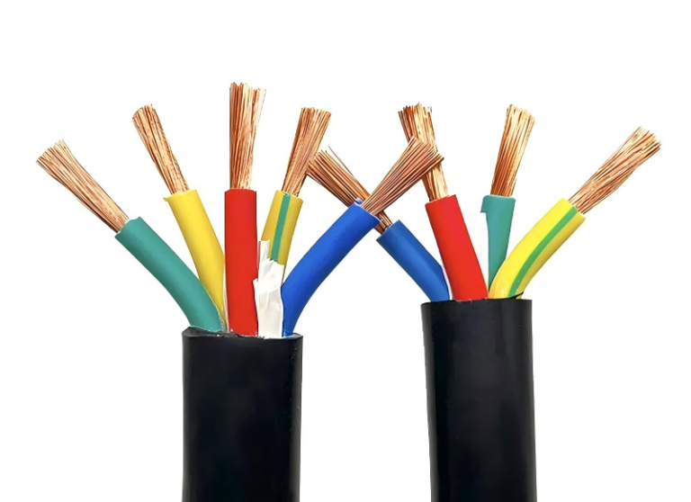
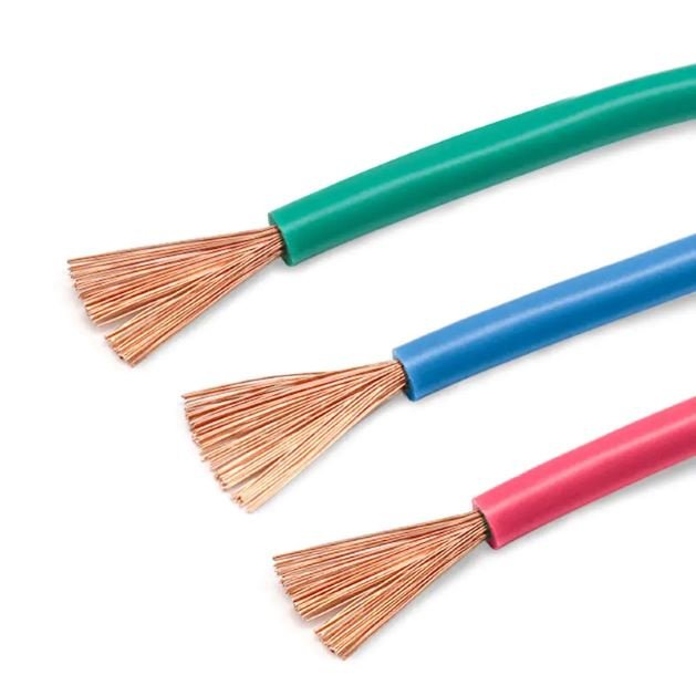
Jinda’s flexible cord portfolio covers the specifications most commonly required across residential, commercial, and industrial applications worldwide. The core lines include H05VV-F thermoplastic-insulated flexible cords rated to 300/500 V, H07RN-F heavy-duty rubber-insulated cables rated to 450/750 V for outdoor and industrial environments, and SOOW-equivalent vulcanized rubber cords built to withstand oil exposure, mechanical abuse, and temperature cycling that would destroy a standard PVC jacket inside a season.
Conductor cross-sections run from 0.75 mm² (suitable for light instrumentation and lamp cord applications) up to 50 mm², which gets you into the territory of portable generator leads and heavy equipment supply cables. That range matters because a procurement team sourcing for a single project often needs multiple specifications — and consolidating that under one supplier with consistent quality control simplifies the audit trail considerably.
Custom-jacketed industrials are also available: halogen-free compounds for tunnel and mining applications, TPE jackets for extreme cold down to roughly -40 °C, and specialized formulations for resistance to specific chemicals where a generic neoprene or PVC jacket would degrade within months. The construction parameters — stranding class, jacket wall thickness, filler configuration — are adjustable to application requirements rather than fixed catalog options.
Manufacturing Scale and Lot-to-Lot Consistency
Five production bases across China, totaling 470,000 m² of manufacturing space, gives Jinda the capacity to handle both sample quantities for engineering evaluation and multi-container bulk orders on a consistent schedule. In practice, lot-to-lot consistency is where a lot of mid-tier cable manufacturers fall apart. If the conductor resistance on your first shipment is within spec but your third shipment runs 8–10% higher, your voltage drop calculations become unreliable — exactly the kind of drift that contributes to the overloading scenarios discussed earlier in this article.
Jinda operates five production bases in China with over 470,000 m² of total manufacturing space and ships to more than 50 countries.True
This matches the company's stated manufacturing footprint and export reach as disclosed in official company documentation.
Quality Assurance and Testing Infrastructure
In-house testing covers the parameters that actually predict field performance: conductor DC resistance per IEC 60228, insulation breakdown voltage, jacket abrasion resistance, and flame retardancy per IEC 60332-1 and IEC 60332-3. For North American export, UL 62 and CSA C22.2 No. 49 compliance testing is conducted to support certification requirements — not just claimed on a spec sheet. RoHS compliance with full material traceability documentation is standard, which procurement auditors in the EU and UK increasingly require before approving a new supplier.
CE and VDE marks are available on applicable product lines. That combination of European and North American certification coverage is genuinely useful for projects supplying equipment into multiple markets from a single cable source.
Technical Support and Custom Assembly
Jinda’s application engineering team can work through load calculations, conductor sizing for specific voltage drop budgets, and site-specific cord assembly design — the kind of consultation that prevents the wrong specification from being ordered in the first place. Custom cord assembly services include cut-to-length production, connector termination, coiling, and OEM labeling. For a factory or equipment manufacturer, receiving a finished, tested cord assembly rather than bulk reel stock eliminates the field termination step where most installation errors actually occur. That alone reduces the temptation — and the hazard — of patching together whatever happens to be available.
Inspection, Maintenance, and Documentation Protocols for Extension Cords in Industrial Settings
A surprising number of cord failures in industrial facilities aren’t caused by overloading or daisy-chaining — they’re caused by cords that were visibly damaged weeks earlier and nobody pulled them from service. That’s the real operational problem. The physics and the codes matter, but execution on the floor is what keeps people safe.
Pre-Use Visual Inspection: What OSHA and NFPA 70E Actually Require
OSHA 29 CFR 1910.303 and NFPA 70E Section 130.7 both establish that flexible cords must be visually inspected before each use in industrial environments. In practice, this means the person picking up the cord takes 30–60 seconds to run it through their hands before plugging anything in. They’re looking for cut or abraded jacket, kinking or crush damage from forklift traffic or pinched door edges, discoloration at either plug end (heat discoloration near the pins is a serious indicator — usually tan or brown staining on the plug body, sometimes a faint smell), and bent, corroded, or missing ground pins. A missing ground pin alone is an immediate remove-from-service event. No exceptions.
The inspection has to be documented. A verbal check-in-your-head doesn’t count for OSHA compliance. A simple daily-use log — cord ID, date, inspector’s initials, pass/fail — kept either on paper or in a CMMS system is sufficient. Facilities with dozens of cords in rotation often attach the log sheet directly to a cord reel or storage hook.
Periodic Electrical Testing: The Numbers That Matter
Visual inspection catches mechanical damage. It doesn’t catch insulation that’s degraded from heat cycling or absorbed moisture. For cords in continuous industrial service, periodic electrical testing fills that gap.
Insulation resistance should measure above 1 MΩ when tested at 500 V DC between each conductor and the ground conductor, and also conductor-to-conductor. A reading trending downward across successive tests — say, dropping from 50 MΩ to 8 MΩ over two quarterly tests — is a retirement signal even if the cord hasn’t failed the threshold yet. Ground conductor continuity should read below 0.1 Ω end-to-end; higher resistance in the ground path means fault current won’t clear the breaker reliably. Contact resistance at the plug and connector body is worth checking on high-cycle cords — corroded or pitted contacts add resistance and localized heating.
Testing frequency depends on environment and use intensity. Light-duty office cords might warrant annual testing. A cord running a 15 A load in a foundry with temperature swings and coolant mist exposure probably needs quarterly testing.
Color-Coded Tagging: Simple and It Works
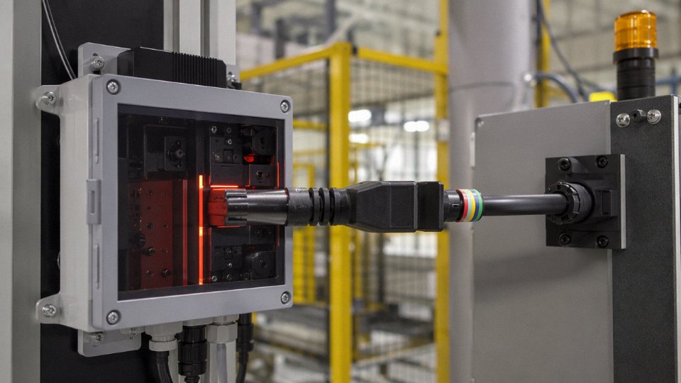
A quarterly color rotation system — assign a color (usually colored electrical tape wrap or a plastic hang tag) to each calendar quarter, inspect every cord in the facility, and replace the tag — gives supervisors and auditors an instant visual snapshot of whether any cord has missed an inspection cycle. If it’s Q3 and you see a Q1 tag, that cord hasn’t been checked in six months and gets pulled immediately. It costs almost nothing to implement.
Storage and Handling
Cords coiled tighter than roughly 8–10× their outer diameter will stress the insulation at the bend points over repeated cycles. Store cords on hooks or reels, off the floor — concrete floors wick moisture, and prolonged contact degrades PVC jackets faster than most people expect, especially in seasonal temperature extremes. Damaged or suspect cords need a physical “Out of Service” tag and segregated storage, not just a mental note.
Retirement Criteria: When the Cord Goes in the Bin
Any cord with insulation repaired using electrical tape gets retired. Tape is not a listed repair method. A replaced plug is acceptable only if it’s a factory-crimped or listed repair connector installed per the manufacturer’s instructions — a plug wrestled on with a screwdriver in the maintenance shop is not. Cords with a history of repeatedly tripping their circuit breaker indicate chronic overloading and should be retired or derated to a lighter application.
Any extension cord with insulation repaired using standard electrical tape meets OSHA requirements for continued use if the repair covers the damaged area completely.False
OSHA 29 CFR 1910.305(g)(2)(ii) requires that flexible cords be free of splices or taps. Electrical tape is not a listed repair method for flexible cord insulation, and a taped repair does not restore the cord's listed rating. The cord must be removed from service.
Record-Keeping as a Compliance Asset
Inspection logs, test records, cord ID numbers, and retirement documentation belong in the facility’s electrical safety management system — not in a supervisor’s desk drawer. In the event of an incident, an auditor or investigator will ask for these records. Gaps in the log are often treated as evidence of a systemic failure, not just an administrative oversight. Assign cord ID numbers with asset tags at the time of procurement, log them in on arrival, and track them through to disposal. It’s roughly the same discipline as managing hand tools or PPE, and in a well-run facility it fits naturally into existing maintenance workflows.
Frequently Asked Questions About Power Cord Safety and Daisy-Chaining
Is it ever legal to plug one extension cord into another?
It depends heavily on where you’re doing it. In a private residence, no U.S. federal statute will cite you for it — but that’s a low bar. The NEC commentary and NFPA fire safety guidance both strongly discourage the practice, and the roughly 3,300 extension-cord-related home fires reported annually in the United States make “technically not illegal at home” a hollow defense.
In any workplace covered by OSHA — general industry, construction, maritime, you name it — the answer is unambiguous. OSHA 29 CFR 1910.305(g) explicitly prohibits using flexible cords as a substitute for fixed wiring, and daisy-chaining extension cords is a textbook citable violation. Inspectors do write these up. The fine itself is often modest, but the incident report that follows an arc fault or a fire is not.
OSHA 29 CFR 1910.305(g) makes daisy-chaining extension cords a citable violation in all general industry and construction workplacesTrue
OSHA 29 CFR 1910.305(g)(1)(iv) prohibits flexible cords and cables from being used as a substitute for fixed wiring of a structure, which OSHA enforcement has consistently interpreted to include connecting multiple extension cords in series.
Does using a higher-rated cord as the second link make the chain safe?
No, and this is one of the most persistent misconceptions on the shop floor. The assembly is only as capable as its weakest point, and that point is almost always the female receptacle on the first cord — not the conductor of the second. A 12 AWG cord plugged into a 16 AWG cord’s outlet doesn’t upgrade the system to 20 A capacity. The connector joint is where resistance concentrates, where heat builds, and where insulation degrades first. Conductor gauge in the second cord is largely irrelevant to that failure mode.
Can I plug a power strip into an extension cord?
Sometimes, within limits. A UL-listed surge protector or power strip connected to a single properly rated extension cord is acceptable in residential and some light commercial contexts — provided the combined load of every device on that strip stays within the cord’s ampacity, the cord gauge is appropriate for both the load and the run length, and you’re not in an OSHA-covered workplace. Even then, this is a temporary arrangement. It is not a substitute for adequate receptacle placement, and it should never be routed under carpet or through doorways where mechanical damage accumulates quietly over months.
How long can an extension cord be before it becomes dangerous?
Length alone isn’t the hazard. Undersized conductors for the actual load at that length — that’s the problem. Use NEC Table 400.5 or a basic voltage drop calculator. The common engineering targets: keep voltage drop below 3% for anything sensitive (controls, computers, variable-frequency drives) and below 5% for general resistive loads. A 16 AWG cord running a 12 A load over 50 ft will hit that 5% threshold. The same load on 12 AWG over the same distance won’t. Size to the distance, not just the nameplate current.
What is the maximum wattage a standard 16 AWG extension cord can handle?
At 120 V, a 16 AWG cord rated at 13 A gives you a theoretical ceiling around 1,560 W. Apply the 80% continuous load derating the NEC requires for circuits carrying load for three hours or more, and the practical working limit drops to roughly 1,250 W. At 240 V, the same conductor can deliver proportionally more power at the same current — which is why European and industrial applications on 230–240 V systems can run higher-wattage equipment through the same wire cross-section that would be marginal at 120 V.
Are there industrial connectors designed to safely extend power cords?
Yes, and they’re meaningfully different from simply plugging one cord into another. Listed in-line cord connectors — devices rated to UL 498 or IEC 60309 — provide a fully enclosed, strain-relieved, weatherproof junction with contact ratings that match or exceed the conductors. These are standard on temporary power distribution rigs at construction sites and outdoor events. The connector is engineered for the purpose: the contacts are sized, the housing is rated, and the strain relief prevents the mechanical tugging that loosens contacts over time. Plugging one extension cord into another gives you none of those protections. If you need a reliable, inspectable junction point in a flexible cord run, a listed in-line connector is the right tool.
Summary: The Right Cable, the Right Length, the First Time
Plugging one power cord into another is not a gray area. It is an OSHA-citable violation under 29 CFR 1910.305(g) in any U.S. workplace, it conflicts with NEC Article 400 and IEC 60884-1, and it creates thermal, arc fault, and grounding failure risks that standard branch-circuit breakers are not designed to catch. A 15 A breaker protects the wiring in the wall — it does not protect two undersized cords whose combined resistance is quietly turning electrical energy into heat at every connection point. By the time a breaker trips, the cord jacket may already be degraded or an arc event may already have ignited nearby material.
Daisy-chaining extension cords is a citable OSHA violation in U.S. workplacesTrue
OSHA 29 CFR 1910.305(g)(1)(iv) explicitly prohibits the use of flexible cords as a substitute for fixed wiring, which includes connecting cords in series to extend reach. Inspectors cite this routinely during general industry audits.
The thermal risk is real and cumulative. Each additional connector in the chain adds contact resistance. Under load — especially a load that cycles on and off, or a motor load with startup inrush — those connections heat and cool repeatedly, the contacts work-harden or oxidize, and resistance climbs further. Ground continuity degrades through the same mechanism. A ground fault downstream of a corroded plug-to-socket connection may not return enough fault current to trip the breaker at all. That is the scenario that injures people.
The Engineering Fix Starts Before Procurement
Most improvised cord connections happen because the original cord specified was too short, too light for the actual load, or missing the environmental jacket the application actually needed. That is a specification error, and it is completely avoidable.
The correct sequence is straightforward, though it gets skipped surprisingly often under schedule pressure. Establish the total connected load in amps — accounting for motor inrush if applicable, not just steady-state draw. Measure the actual routing distance, not the straight-line distance; cable routed around machinery, through conduit entries, or along elevated cable trays is almost always longer than it looks on a drawing. Select a single cord or cable of the appropriate gauge for that combined load and distance, keeping voltage drop within the limit your equipment requires (typically 3–5% for sensitive electronics, up to 10% for resistive heating loads). Specify the correct jacket material for the environment — SOOW for wet or outdoor industrial use, SJOOW for lighter-duty indoor-outdoor, TPE or PUR for high-flex or chemically exposed applications. Use listed connectors rated for the full circuit current. Document it. Inspect it on a regular interval and replace it when the jacket shows cuts, crushing, or when plug blades show discoloration.
That process eliminates the problem entirely. There is no legitimate scenario in a properly engineered installation where a second cord needs to be added end-to-end.
How Jinda Eliminates the Problem at the Source
Shandong Jinda Special Cable Group manufactures flexible cords and extension cables to IEC, UL, and a range of national standards, with custom cut-to-length capability across five production bases in China. If your application requires 18 meters of 2.5 mm² H07RN-F for a European market installation, or 40 feet of 12 AWG SOOW for a North American industrial site, Jinda can supply the correct cable as a single continuous run — no field splicing, no cord-to-cord connection, no compromise.
The engineering consultation is part of the service. Provide your load in amps, routing length, operating environment (temperature range, exposure to oil, UV, or mechanical flex cycles), and destination market, and Jinda’s technical team can recommend the specific construction, conductor cross-section, and jacket material that matches the application — with a quotation included.
Jinda supplies customers in more than 50 countries. The logistics infrastructure, documentation for customs and compliance, and the technical depth to support specification from initial inquiry through delivery are all in place.
Get the specification right before the cable ships, and the temptation to daisy-chain never arises.
Contact Jinda’s technical team at the inquiry link below with your load, length, environment, and destination market. One conversation at the procurement stage prevents months of safety liability on the plant floor.