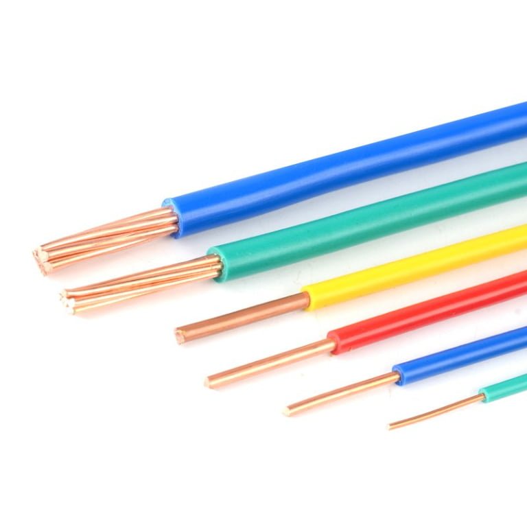
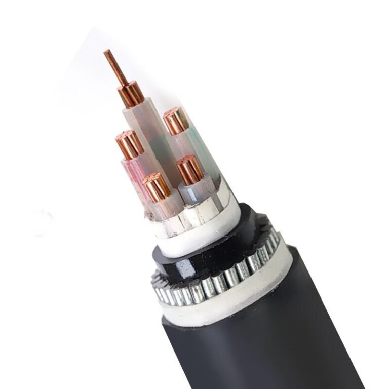
The wrong power cord quietly destroys equipment and inflates energy bills long before anything fails visibly. Undersized conductors run hot, degrade insulation from the inside out, and introduce enough resistive loss that sensitive electronics — CNC controllers, variable-frequency drives, medical imaging units — operate outside their design voltage window. That 1.5 mm² cord somebody grabbed from the spares bin to replace a 2.5 mm² original isn’t a minor substitution; at 13 A over a 5 m run, you’re already looking at up to 2.2 V drop and a conductor that’s slowly cooking its own jacket. The financial consequence compounds: voided equipment warranties, shortened insulation life, and in worst cases, a thermal event that takes a production line down for days.
Yes, the power cord you use matters significantly. Conductor cross-section, insulation rating, certification status, and cord length all directly affect voltage delivery, heat generation, and safety compliance. Using an undersized or uncertified cord can cause equipment damage, energy waste, and regulatory non-compliance — and in industrial settings, the consequences scale fast.
What surprises most procurement managers is how much variation exists inside the category they treat as a commodity. A cord is a cord until it isn’t — until the insulation resistance on an unvetted batch tests below 10 MΩ after six months of thermal cycling, against the 100 MΩ minimum a UL-listed product must hold at 500 V DC. The gap between those two numbers isn’t academic. It’s the difference between a predictable 10-year service life and a slow-motion failure that nobody traces back to the cord until after the damage is done.
Current Rating and Conductor Cross-Section: How Undersizing Destroys Equipment
The physics here are unforgiving. Every copper conductor has a resistivity of roughly 1.72 × 10⁻⁸ Ω·m at 20 °C — annealed copper, the standard for flexible cord conductors. Resistance scales inversely with cross-sectional area, so halving the area doubles the resistance per metre. Power dissipated as heat follows I²R, which means resistance differences get amplified by the square of the current you’re pushing through.
Work through a concrete example. A 0.75 mm² conductor has a resistance of approximately 24.4 mΩ/m. A 1.5 mm² conductor runs about 12.1 mΩ/m. At 10 A, the 0.75 mm² cord dissipates I²R = 100 × 0.0244 = 2.44 W per metre. The 1.5 mm² cord dissipates 100 × 0.0121 = 1.21 W per metre. That’s roughly 3.2× the heat generation per metre in the undersized cord — and that heat has nowhere to go except into the insulation surrounding it.
Ampacity Reference: What the Standards Actually Say
IEC 60227 and IEC 60245 define the ratings for flexible PVC and rubber-insulated cords. UL 62 covers the North American equivalents. The values aren’t identical — installation method, ambient temperature, and insulation class all shift them — but the core guidance is consistent enough for procurement decisions:
| Conductor cross-section | IEC 60227 / 60245 continuous rating | UL 62 approximate equivalent |
|---|---|---|
| 0.75 mm² | 6 A | ~7 A (AWG 18 flexible) |
| 1.0 mm² | 10 A | ~10 A (AWG 17/16 range) |
| 1.5 mm² | 13 A | ~13 A (AWG 14 flexible) |
| 2.0 mm² | 16 A | ~15–16 A |
| 2.5 mm² | 20 A | ~20 A (AWG 12 flexible) |
AWG-to-mm² mapping isn’t exact; always verify against the specific UL 62 table for the cord construction you’re sourcing.
The Thermal Runaway Cascade
Elevated conductor temperature is where the slow damage begins. PVC insulation starts losing mechanical integrity somewhere in the 70–90 °C range depending on compound grade — and a chronically overloaded 0.75 mm² cord running at 10 A in a 35 °C ambient can easily push conductor temperature above that threshold within an hour of continuous operation. The insulation softens. In a bundled or constrained application it can creep under mechanical pressure, thinning at contact points. Dielectric strength drops. Phase-to-phase or phase-to-ground contact becomes possible. At that point you’re no longer managing a slow efficiency loss — you’re managing the conditions for a short circuit or ground fault, and in worst cases, ignition of the insulation itself.
A chronically undersized power cord poses a genuine fire risk due to I²R heating causing insulation breakdown, not merely an efficiency concern.True
This is consistent with the thermal runaway mechanism described in IEC 60364-4-43 and NFPA 70 Article 400 commentary — insulation degradation from sustained overtemperature is a documented root cause in cord-related electrical fires.
Voltage Drop: The Load-End Damage You Don’t See Immediately
The 5-metre, 1.5 mm² cord at 13 A example from the IEC data is worth spelling out. Resistance of a 5 m run (10 m total circuit length, both conductors): 10 × 0.0121 = 0.121 Ω. Voltage drop: 13 × 0.121 ≈ 1.57 V, consistent with the 1.8–2.2 V range that accounts for connector resistance and conductor temperature rise. On a 230 V circuit that’s under 1% — tolerable. Substitute 0.75 mm² and conductor resistance roughly doubles, so your voltage drop pushes toward 3–4 V. That doesn’t sound dramatic until you’re powering a single-phase induction motor, where a 2–3% supply voltage reduction can increase motor current by 4–6%, adding heat at the motor windings on top of the cord losses. The two failure mechanisms reinforce each other.
Bundled and Coiled Cords: The 30–40% Ampacity Penalty
Most people understand the rated current on the label. Fewer account for what happens when the cord is coiled on a storage reel or bundled tightly with other cables in a cable tray or drag chain. Convective cooling — which is responsible for a substantial share of heat dissipation in free-air rated conductors — drops sharply when airflow around individual conductors is blocked. The practical result is a derating of 30–40% depending on how many turns are coiled and how tightly. A 1.5 mm² cord rated at 13 A free-air might safely carry only 8–9 A when wound on a full drum. Extension reels used in manufacturing environments are a routine offender here; a cord reel with most of the cable still wound up while powering a 10–12 A tool is running close to or above its thermally derated limit, often for extended periods.
The Procurement Rule to Write Into Your Specifications
Size for 125% of the maximum continuous load current. This follows both IEC 60364-5-52 and NEC Article 400 logic, and it gives you real headroom for ambient temperature variation, bundling effects, and the gradual resistance increase that comes with connector oxidation over service life. A 10 A continuous load needs a cord rated for at least 12.5 A — which points to 1.5 mm² minimum, not 1.0 mm². That one cross-section step up costs very little in unit price and avoids a failure mode that, once triggered, is rarely cheap to resolve.
Voltage Class, Insulation Grade, and the Hidden Dielectric Risks
Most engineers know to check conductor sizing. Far fewer check the voltage designation printed on the cord jacket — and that’s where the genuinely dangerous failures hide.
Understanding the Voltage Designation Codes
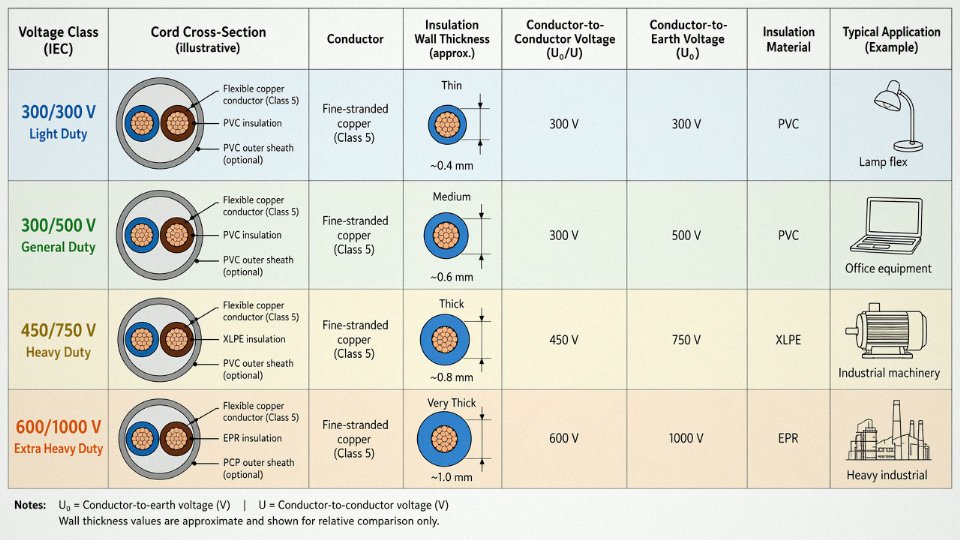
IEC-rated flexible cords carry a two-number voltage designation. The first figure is the rated conductor-to-conductor voltage; the second is the conductor-to-earth voltage. A 300/300 V cord is light-duty — lamp flex, small appliance tails, nothing that sees a real industrial environment. The 300/500 V designation covers general domestic and commercial use: your typical kettle lead or office equipment cord. Step up to 450/750 V and you’re in industrial flexible territory — machinery, control panels, equipment that moves or flexes in service. At 600/1000 V you’re looking at heavy industrial and some fixed-wiring applications.
The gap between these classes is not a comfortable safety margin. It is an engineering limit. A 300/500 V cord installed on a 480 V delta industrial circuit — which is fairly common in North American plants where someone grabbed whatever was in the stores — is operating at over 150% of its rated phase-to-earth voltage. That doesn’t trip a breaker. It doesn’t blow a fuse. It accelerates insulation aging invisibly and continuously.
What the Insulation Is Actually Doing
Insulation is not just a covering. It is the dielectric barrier preventing current from taking an unintended path — through a cabinet wall, through a wet concrete floor, through a person. The material and wall thickness together determine how well it holds that barrier under voltage stress and heat.
Standard PVC at 60°C handles low-stress applications adequately when new. PVC rated to 75°C has better plasticiser retention under moderate thermal load, though it still embrittles over time in flexing applications. XLPE — cross-linked polyethylene — reaches a 90°C rating through a curing process that creates a three-dimensional polymer network, making it significantly more resistant to thermal aging and deformation under load. EPR (ethylene propylene rubber) also rates to 90°C and adds something XLPE doesn’t: genuine flexibility at low temperatures, which matters in cold stores, outdoor winter installations, or anywhere the cord bends repeatedly.
The practical difference shows up over years, not days.
Dielectric Breakdown: The Aging Mechanism
Fresh insulation on a quality cord typically measures around 18–22 MV/m dielectric strength — give or take, depending on material and wall thickness. As the cord ages under combined thermal and voltage stress, polymer chain scission degrades molecular weight. The insulation doesn’t look different from outside. The jacket may still feel supple. But dielectric strength can drop toward the 5–7 MV/m range where partial discharge becomes probable — small internal arcs that erode the insulation from within, eventually leading to puncture.
Running a cord above its voltage class compresses that aging timeline substantially. What might take a decade under rated conditions can happen in two or three years of misapplication.
A 300/300 V cord used on a 480 V delta circuit operates beyond its rated conductor-to-earth voltage.True
The second number in the designation (300 V) represents the conductor-to-earth rated voltage. A 480 V delta circuit presents up to 480 V phase-to-earth under fault conditions, exceeding that rating by over 50%.
The Insulation Resistance Test as a Maintenance Habit
A decent 450/750 V industrial cord in good condition should read well above 100 MΩ when tested at 500 V DC. In practice, anything above 100 MΩ is serviceable; readings that have dropped below 10 MΩ warrant close attention; below 1 MΩ, take the cord out of service immediately. That reading indicates moisture ingress, physical insulation damage, or thermal degradation — none of which is a borderline condition.
This test takes about two minutes with a basic megohmmeter. Most plants don’t do it on a schedule. They should.
A cord running into a multi-outlet strip is often overlooked entirely in periodic inspection rounds. If that strip feeds mixed equipment — some 120 V, some 240 V — and someone has substituted a light-duty 300/300 V cord for a failed original, the hazard sits there drawing no attention until it doesn’t.
Spark Testing Through Full Production Length
One of the failure modes that causes field problems is a pinhole defect in the insulation wall — a gap too small to see, usually caused by a contaminant particle or a momentary extrusion irregularity. Under normal operating voltage these may go undetected for months before partial discharge begins. Jinda runs continuous high-voltage spark testing at 4 kV AC along the full production length of every flexible cord run, not sampled lots. A pinhole collapses the spark gap and trips the detector immediately. The cord doesn’t reach the reel. This is a straightforward process quality step, but it requires capital investment in inline test equipment and the operational discipline to actually halt production rather than flag and continue — which not every supplier does.
The voltage class on a cord jacket is a real engineering specification. Treat it as one.
Matching Cord Construction to Environmental Duty: Oil, Heat, Cold, and Mechanical Abuse
A standard PVC power cord works fine on a desktop printer in a climate-controlled office. Put that same cord on a CNC lathe with coolant mist, a food-processing line that gets steam-cleaned twice a shift, or a robotic welding cell running 18 hours a day — and you’re looking at premature jacket cracking, insulation breakdown, and eventually a fault that takes down a machine or, worse, a person. The choice of jacket material and conductor construction isn’t an aesthetic decision; it’s an engineering one, driven by the actual stressors in the application.
Hydrocarbon Oils and Chemical Splash
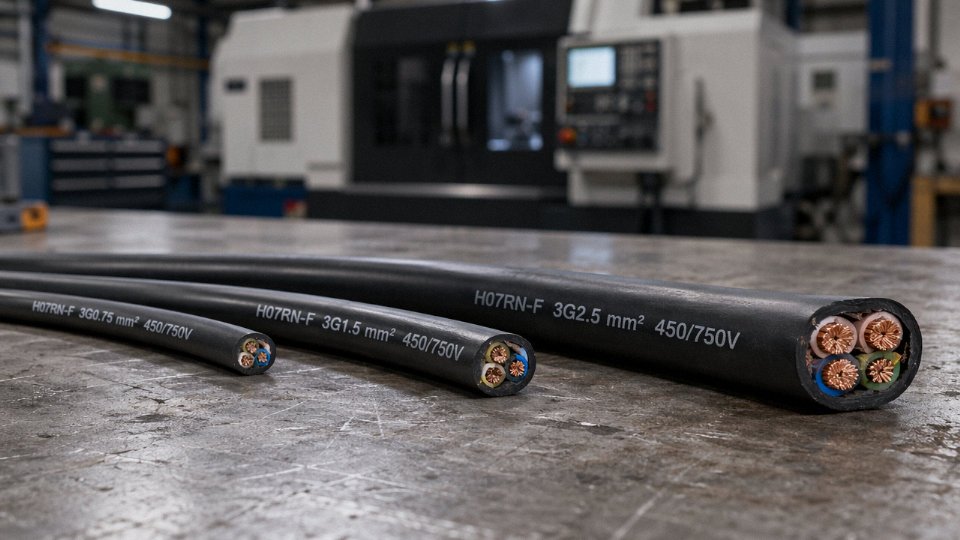
Standard PVC softeners (plasticizers) leach out when the jacket contacts petroleum-based cutting fluids, hydraulic oil, or lubricants. The cord stiffens, micro-cracks form, and insulation resistance starts falling — usually within months of installation in a heavy machining environment. The fix is straightforward: specify a neoprene (polychloroprene) or polyurethane (PUR) outer jacket. The IEC H07RN-F designation covers exactly this case — heavy-duty rubber insulation with a neoprene or similar elastomeric outer sheath, rated for oil-resistance and rough industrial handling. In practice, H07RN-F is the de facto standard on European machine tools and portable industrial equipment for good reason. PUR goes a step further in abrasion resistance and handles a broader chemical range, which matters in petrochemical or paint-shop environments where the splash chemistry varies.
Elevated Ambient Temperature
Above roughly 60 °C — near ovens, furnaces, or in poorly ventilated electrical enclosures — standard PVC insulation softens and can deform under conductor pressure, reducing effective insulation wall thickness and dropping dielectric integrity. Silicone-insulated cords handle continuous service up to 180 °C and intermittent peaks higher than that. XLPE (cross-linked polyethylene, suffix “B” in IEC cord type codes) is a practical middle ground: good thermal stability to around 90 °C continuous, better chemical resistance than PVC, and lower dielectric losses. Neither silicone nor XLPE is cheap, so specifying them where PVC would actually survive just inflates BOM cost — but in the right application, the alternative is re-wiring the machine after a heat-related failure every 12–18 months.
Sub-Zero and Cold-Storage Environments
Standard PVC becomes brittle below roughly -5 to -10 °C. Bend a PVC cord at -20 °C and you can crack the jacket cleanly. Cold-storage facilities, outdoor installations in northern climates, and refrigeration plant rooms need either cold-flexible PUR or EPR (ethylene propylene rubber) jacketed cords rated to -40 °C. These materials maintain elasticity at low temperature, which means a cord routed through a blast-freezer door seal or along an outdoor cable tray in winter won’t develop stress fractures every time someone moves it.
Continuous Flexing and Robotic Applications
This is where conductor stranding matters as much as jacket material. A standard Class 2 conductor (relatively few, thick strands) in a PVC jacket might survive fewer than 200,000 flex cycles at a dynamic bending radius of 5× the cable’s outer diameter. A fine-stranded Class 5, and especially Class 6 per IEC 60228, in a PUR drag-chain jacket typically achieves upward of 10 million flex cycles under the same conditions — the difference between replacing a cable annually and running it for the life of the machine. Robotic arms, CNC tool-changers, and automated guided vehicles all demand Class 5 or Class 6 conductors. Specifying Class 2 because it’s cheaper is a false economy that shows up in maintenance logs.
A fine-stranded Class 6 conductor in a PUR jacket can achieve 10 million or more flex cycles at a dynamic bending radius of 5× cable outer diameter under IEC 60228 test conditions.True
This performance range is consistent with published test data from IEC 60228 Class 6 PUR drag-chain cables and is a standard specification cited by industrial cable manufacturers for robotic and CNC applications.
UV and Ozone Degradation Outdoors
Standard PVC loses tensile strength progressively under UV exposure — degradation reaching up to 60% after roughly 1,000 hours per ASTM G154 accelerated weathering protocols, depending on the specific compound and carbon black content. For outdoor cable runs, specify UV-stabilised PUR or carbon-black-filled polyethylene jacket compounds. These retain above 80% tensile strength under equivalent exposure. Ozone is a separate but related concern in coastal or high-altitude sites; EPR and neoprene handle ozone attack significantly better than standard PVC.
Decoding IEC Cord Type Designations
The IEC harmonized cord coding system gives you a compact description of the entire construction once you know the logic. “H” means harmonized European standard. The number (03, 05, 07) indicates voltage class — H03 for 300/300 V light duty, H05 for 300/500 V, H07 for 450/750 V heavy duty. The suffix letters describe insulation and jacket: V = PVC, R = rubber, N = neoprene, B = XLPE. So H07RN-F means 450/750 V, rubber-insulated, neoprene-jacketed, flexible stranded conductor. Once you can decode the designation, a datasheet or a supplier’s product list becomes far easier to navigate.
Practical Duty-Class Selection Reference
| Environment | Conductor Class | Insulation | Outer Jacket | IEC Designation (Typical) |
|---|---|---|---|---|
| Indoor dry, light loads | Class 2 | PVC | PVC | H05VV-F |
| Indoor wet / wash-down | Class 5 | Rubber | Neoprene | H07RN-F |
| Outdoor / UV exposure | Class 5 | XLPE or PUR | UV-stabilised PUR | H07BQ-F (or equivalent) |
| Oil splash / machining | Class 5 | Rubber | Neoprene or PUR | H07RN-F / PUR variant |
| High-flex / drag chain | Class 6 | PUR | PUR | Manufacturer-specific PUR drag chain |
| Cold storage (to -40 °C) | Class 5–6 | EPR | Cold-flex PUR or EPR | Rated cold-flex designation |
| Food-grade / clean-room | Class 5 | Silicone or PUR | Food-grade PUR | Manufacturer-specific, FDA-compliant |
Jinda’s H07RN-F range and purpose-built PUR drag-chain cords — produced at the Shandong manufacturing bases — are engineered specifically for these demanding categories, with conductor stranding, jacket compound, and testing all matched to the operating environment rather than minimum-cost compliance.
One practical note: even with the right jacket and conductor class, an installation that ignores minimum bend radius or uses improper cable glands will defeat the engineering. The cable is only as good as the termination and routing around it.
Certification Marks Decoded: UL, VDE, HAR, SAA, and What Absence of a Mark Actually Means
A certification mark on a power cord is not a sticker. It represents a documented chain of testing, factory surveillance, and ongoing compliance — or it should. The gap between what a mark promises and what some cords actually deliver is where procurement mistakes become liability events.
The Six Marks That Matter Commercially
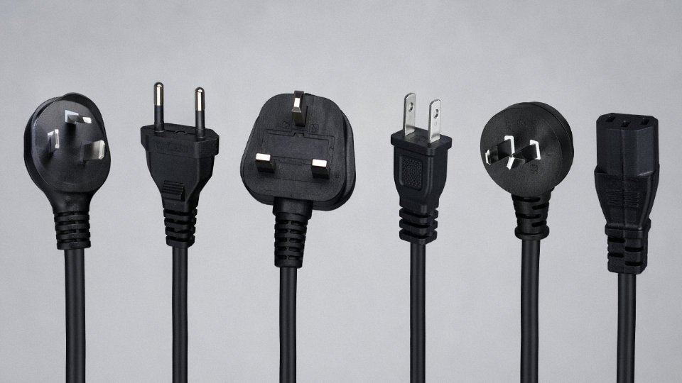
UL / cUL (North America) — UL certification under UL 62 (flexible cords and cables) and CSA 22.2 No. 49 covers the Canadian market under the cUL variant. These aren’t one-time type tests. UL runs what it calls Follow-Up Services: unannounced factory inspections where production samples get pulled from the line and tested against the original certification baseline. A factory that fails to maintain compliance must stop applying the mark within 30 days — in practice, that’s a hard stop with customs and retailer consequences attached. For North American OEM supply, no substitute exists.
HAR (European Harmonised) — The HAR mark, a small triangle enclosing the letters HAR, is arguably the most operationally efficient certification path for cords sold across Europe. It operates under CENELEC HD 21 (PVC-insulated) and HD 22 (rubber-insulated) standards and is mutually recognised across 22 participating national bodies. Get certified through, say, KEMA in the Netherlands or BSI in the UK, and that approval travels with the cord into Germany, France, Poland, and the rest. No re-testing per country. For distributors managing multi-country European stock, HAR eliminates the kind of duplicated certification cost that can quietly erode margins on mid-volume orders.
VDE (Germany) — VDE goes further than HAR in one important respect: quarterly factory audits, not just product testing. The VDE mark signals that the manufacturing process itself has been reviewed recently, which matters for high-specification industrial applications where cord construction consistency is as important as the initial type test. German machine builders often specify VDE explicitly in their bill-of-materials.
SAA / RCM (Australia and New Zealand) — Per AS/NZS 3191, flexible cords for the Australian and New Zealand markets require RCM registration (the Regulatory Compliance Mark replaced the old SAA mark, though “SAA” still circulates informally in procurement documents). Enforcement sits with state-level electrical regulators, and product liability for non-compliant imports lands squarely on the importer of record.
PSE (Japan) — Mandatory for Class II appliance cords under the Electrical Appliances and Materials Safety Act. The diamond PSE symbol (as opposed to the circle) applies to specified high-risk products; flexible cords fall under this category. Selling uncertified cords into Japan through e-commerce platforms doesn’t make the requirement go away — it just shifts enforcement to the platform and the import agent.
SASO (Saudi Arabia) — The Saudi Standards, Metrology and Quality Organization requires SASO certification for cords entering Saudi Arabia and increasingly the broader Gulf market. The technical requirements align loosely with IEC standards, but the administrative path — Saudi product registration, third-party testing through an approved lab — is separate and takes time to plan for. Procurement teams building Middle East distribution often underestimate the lead time.
Verifying Authenticity: Don’t Assume, Look It Up
Every major certification body maintains a searchable online registry. UL’s is at iq.ul.com — you’ll need the manufacturer name, the cord model or file number, and ideally the cable construction to confirm a specific listing maps to the product in front of you. VDE offers a certificate search at vde.com/en/institute/services/certification. HAR marks can be traced through the national body that issued them, listed on the CENELEC HAR agreement register.
Industry estimates suggest 15–25% of power cords in certain import channels carry certification marks that have not been verified by the issuing certification body.True
This range is consistent with findings from EU market surveillance campaigns and CPSC import enforcement actions on electrical accessories, where counterfeit or self-declared marks are a documented recurring issue rather than an edge case.
That 15–25% figure deserves real attention. A cord with a silkscreened UL mark that doesn’t appear in the UL database is counterfeit, full stop. For OEM brands, the consequences under EU Market Surveillance Regulation 2019/1020 include mandatory withdrawal, public recall, and — where non-compliance is shown to have caused harm — direct importer liability. US CPSC enforcement follows a similar logic. The brand on the finished appliance carries the burden, not the cord supplier who’s already been paid.
In practice, the easiest verification step is also the one most commonly skipped during procurement: cross-referencing the cert mark against the issuing body’s database before the first production order, not after a customs hold.
What Jinda Brings to This
Jinda’s flexible cord product range carries HAR, UL, VDE, SAA, and PSE listings — covering the primary regulatory environments across North America, Europe, Asia-Pacific, and Japan within a single supply relationship. In-house testing includes conductor resistance bridges, high-voltage spark testers running at production line speed, and climate chambers for accelerated thermal aging, meaning certification compliance isn’t just documented at the point of initial type-testing but monitored continuously against production output. For procurement managers consolidating global cord supply, that breadth of in-house certification coverage meaningfully reduces the administrative overhead of managing multiple regional vendors.
Plug and Connector Compatibility: Why the Right Cord Body Is Only Half the Assembly
The cord body gets all the attention — conductor cross-section, jacket material, voltage rating. But in practice, most overheating events and shock hazards I’ve seen traced back to the plug or connector end, not the cable itself. The interface is where mechanical wear, contamination, and assembly shortcuts concentrate.
Contact Resistance: The Failure Mode Nobody Measures Until It’s Too Late
A new, well-made plug contact might show 5–10 mΩ of resistance. Corroded brass, a bent socket clip, or a terminal screw that wasn’t torqued down properly can push that to 0.1 Ω without looking obviously damaged. Run 13 A through 0.1 Ω and you’re dissipating roughly 13 W at that single contact point — continuously, invisibly. A standard PVC plug body softens somewhere around 70–80 °C depending on compound grade. You don’t need much imagination to see where this goes within a few hours of sustained load.
The insidious part: the cord itself measures fine. Continuity checks out. The fault is entirely local to a junction that most acceptance tests don’t probe with enough resolution.
Plug Standards and Current Rating Mismatches
Different markets standardize around different plug geometries, and each carries a current ceiling that’s easy to ignore when you’re just trying to make the physical connection work.
| Plug Standard | Region | Rated Current | Notes |
|---|---|---|---|
| CEE 7/4 Schuko | Germany / most of Europe | 16 A | Earthing via side clips, no fuse |
| IEC 60083 | France / Belgium | 16 A | Central earth pin, not interchangeable with Schuko |
| BS 1363 | United Kingdom | 13 A | Fused at plug; fuse rating must match cord ampacity |
| NEMA 5-15 | North America | 15 A | Polarized, ungrounded variant is NEMA 1-15 |
| AS 3112 | Australia / New Zealand | 10 A standard | 15 A variant exists but less common in field stock |
| IEC 60309 | Industrial (global) | 16 A to 125 A | Colour-coded by voltage; blue = 200–250 V, red = 380–480 V |
The mismatch risk is straightforward: if your cord is sized and terminated for 16 A but the plug fitted to it is an AS 3112 rated at 10 A, the plug becomes the weakest point in the assembly. The cord’s safety margin means nothing downstream of that junction.
Strain Relief — What It’s Actually Supposed to Grip
IEC 60320 requires that a cord-to-plug or cord-to-coupler junction withstand a pull-out force of at least 60 N without the conductors shifting inside the terminal housing. The grip must be on the outer jacket — not the insulated cores. A lot of low-cost moulded plugs wrap their internal clamp around the individual core insulations, which looks fine on a new cord but allows the conductors to creep under repeated flexing or accidental tugging. Once a conductor moves relative to its terminal screw, you’re back to intermittent high-resistance contact. This is particularly common with cords sourced to hit a price point, where the overmoulded plug body and strain relief were clearly designed together only on paper.
Grounding Continuity — The Invisible Safety Requirement
IEC 60364 and NEC Article 250 both set the protective earth conductor’s end-to-end continuity resistance at below 0.1 Ω, measured from the earth pin at the plug through to the equipment chassis connection. On a Class I appliance — anything with a metal enclosure that relies on fault current flowing to ground to trip a breaker — a degraded earth path in the replacement cord is a silent hazard. The equipment looks grounded. The label says grounded. A single corroded crimp in the earth terminal and the fault protection is effectively gone.
A corroded earth connection in a replacement power cord can render a Class I appliance's fault protection ineffective even if continuity appears present on a basic multimeter checkTrue
Standard continuity checks pass below roughly 1–2 Ω, while IEC 60364 requires protective earth resistance below 0.1 Ω for effective fault current clearance. A connection measuring 0.3–0.8 Ω will pass a go/no-go continuity test but may not carry sufficient fault current to trip an overcurrent device within the required time.
IEC 60320 Coupler Ratings — The C13/C14 Overload Problem
C13/C14 connectors are rated at 10 A. C19/C20 step up to 16 A. This is not interchangeable, and yet data centre and server room installations routinely run C13 connectors on PDU circuits protected at 16 A — operating the connector at 160% of its rated current. The connector doesn’t fail immediately. It degrades over months: the contact clips in the C13 socket fatigue, resistance climbs, heat accumulates. C15/C16 couplers, which share the C13 footprint but carry a 120 °C temperature rating alongside the standard 10 A rating, exist specifically for equipment with elevated outlet temperatures — hot-running servers and some catering appliances — but they’re frequently substituted with standard C13 assemblies because the physical fit is nearly identical.
Specifying a Complete, Matched Assembly
The only rational way to specify power cord procurement is as a complete matched set: cord body, plug, and appliance coupler all carrying the same current class, all certified to the relevant market standard, and all assembled and tested as a unit. Buying cord body from one source and plugs from another, then handing them to a technician to assemble in the field, introduces every variable discussed above and removes any single point of accountability.
Jinda supplies factory-terminated cord sets with 100% continuity and ground-bond testing before shipment — which matters precisely because ground-bond testing at the assembly stage catches the corroded crimp and the under-torqued screw before the product reaches a live installation, not after a fault event triggers an investigation.
Extension Cords and Multi-Outlet Strips: The Misuse Patterns That Cause Most Residential and Commercial Fires
The numbers are not abstract. According to NFPA data, electrical cord and plug fires account for roughly 5,300 home fires per year in the United States, with extension cords involved in approximately 3,300 of those events. That is not a freak-accident statistic — it is a misuse statistic. The cord itself is rarely defective. The user just plugged in too much, or used the wrong cord for the job, or left it coiled on a reel at full load on a Friday afternoon.
Extension cords are involved in approximately 3,300 home fires per year in the United StatesTrue
This figure is consistent with NFPA research on home electrical fires attributed to cords and plugs, where extension cords represent the majority subset of cord-involved ignition events.
The Cumulative Load Error Nobody Does the Math On
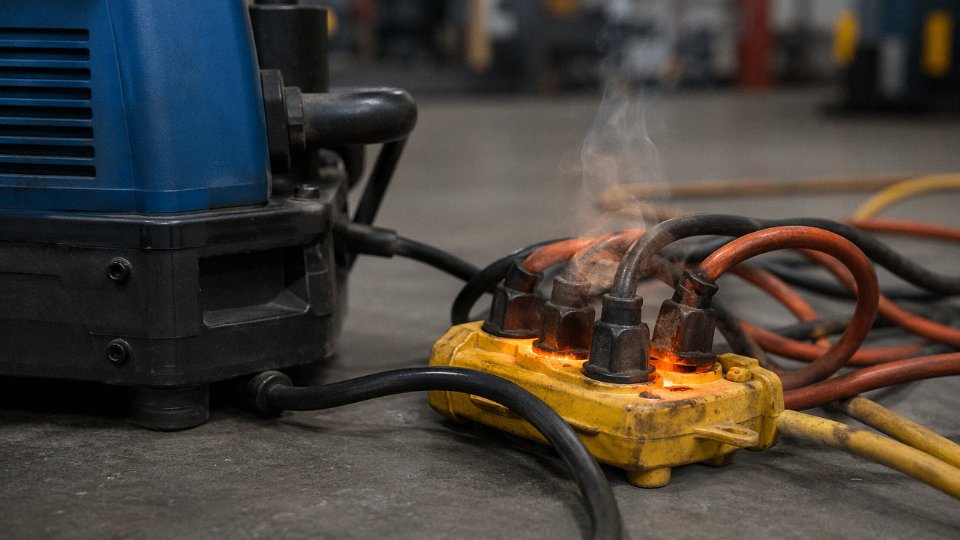
Here is a scenario that plays out constantly in offices and workshops. A 13 A-rated multi-outlet strip gets a 2,000 W space heater plugged into port one — that is already 8.7 A at 230 V. Port two gets a 1,800 W kettle: another 7.8 A. Someone’s laptop charger takes the third slot, adding roughly 1.5 A. Total draw: 18 A, which is 138% of the strip’s rated capacity.
The integrated thermal breaker in a cheap strip is usually calibrated to trip somewhere between 115% and 150% of rating, and it may not trip fast enough to prevent damage to the strip’s internal flex wiring, which is almost always 1.0 mm² or 1.5 mm² regardless of what the marketing copy claims. The breaker protects the upstream circuit. It does not protect the internal conductors of the strip from sustained overtemperature. That distinction matters enormously. The first thing to fail thermally is the wiring inside the strip, not the breaker, and by the time the insulation degrades enough to matter, you may not see any external sign of it until there is a fault.
Daisy-Chaining: Twice the Resistance, Twice the Heat
Running two 5-metre extension cords in series because one cord does not quite reach is extremely common and genuinely dangerous. Two 5-metre 1.5 mm² cords in series serving a 13 A load produce double the voltage drop and double the I²R heating of a single correctly sized 10-metre cord. Each junction — the plug-to-socket interface between the two cords — is also a potential high-resistance point, and contact resistance at an aging socket can easily add another 0.05–0.1 Ω to the circuit. At 13 A, that junction alone dissipates 8–17 W in a space roughly the size of a matchbox. Over hours of use, that is a reliable way to melt plastic.
Just buy the longer cord, specified correctly for the load.
Why Coiled Cords Are a Thermal Trap
A 25-metre extension cord wound on a drum must be fully unrolled before use under any significant load. This is not a suggestion — it is physics. The conductors inside a wound cord cannot dissipate heat laterally because the adjacent turns act as insulation. At full load, a partially unrolled 13 A cord can reach insulation-damaging temperatures in as little as 20–30 minutes, depending on ambient temperature, how many turns remain wound, and the cord’s rated current. In summer, in a plant with poor ventilation, that window shrinks further. Drum-wound cords used in maintenance shops or mobile equipment feeds are a recurring source of exactly this failure mode.
Sizing Extension Cords for High-Draw Appliances
For loads above roughly 2 kW — about 9 A at 230 V or 17 A at 120 V — conductor selection needs to be deliberate. As a working guide aligned with IEC 60884-2-7 for portable socket-outlet assemblies:
| Run Length | Minimum Conductor for Loads up to ~2 kW | Minimum Conductor for Loads up to ~3.5 kW |
|---|---|---|
| Up to 10 m | 2.5 mm² | 2.5 mm² |
| 10–25 m | 2.5 mm² | 4.0 mm² |
| Over 25 m | 4.0 mm² | Specify per voltage-drop calculation |
These figures assume a standard 230 V single-phase circuit with a maximum allowable voltage drop of around 3–5%. At 120 V, current for the same wattage roughly doubles, so size up accordingly and be more conservative.
The Permanent Installation Rule
Extension cords are temporary wiring. That sentence needs to land properly. IEC 60364-4-43 and NEC 400.8 both restrict extension cords from use as permanent or fixed wiring, and for good reason — they lack the mechanical protection, thermal management, and installation oversight of fixed branch circuits. In practice, if a cord longer than about 3 metres is being used routinely to serve a fixed load point, the correct fix is adding a properly installed outlet closer to the equipment. It costs more upfront. It costs far less than a fire investigation, an insurance claim, or a production line shut down because a multi-outlet strip behind a workbench finally gave out.
Industrial and OEM Procurement: How to Write a Power Cord Specification That Protects Your Supply Chain
A purchase order that reads “power cord, 3-pin, black, 1.8 m” is not a specification. It is an invitation for your supplier to make decisions you should be making. In volume procurement — 5,000 units, 50,000 units, a blanket annual order — every ambiguous parameter becomes a substitution risk, and substitutions compound quietly until a warranty return wave or, worse, a field safety incident forces a root-cause investigation back to the cord.
The Seven Parameters That Must Be Explicit
Every cord specification needs at minimum: (1) the IEC or national designation code (e.g., H05VV-F or its NEMA/UL equivalent), which encodes voltage class, insulation system, and construction in one auditable string; (2) conductor cross-section in mm² and stranding class per IEC 60228 — Class 5 fine stranding for flexible cords, not Class 1 solid; (3) insulation material and temperature rating (PVC at 70 °C, rubber at 60–90 °C depending on compound, TPE for cold-store applications down to around −40 °C); (4) jacket material and its operating temperature range, which is a separate call from the insulation; (5) voltage rating stated as U₀/U in volts — 300/500 V is not interchangeable with 450/750 V on an industrial circuit even if the plugs fit; (6) required certification marks with certificate numbers — specifying “UL Listed” without a certificate number allows a supplier to print the mark without holding a valid listing; (7) overall outer diameter with a ±tolerance, typically ±0.2 to ±0.3 mm depending on cable family, because OEM strain reliefs and panel grommets are machined to fit a specific OD range.
Drop any one of these and you are trusting the supplier’s defaults. That trust is occasionally warranted and frequently misplaced.
Incoming Inspection: AQL Sampling and the Four Minimum Tests
For a 10,000-unit shipment, AQL 1.0 at general inspection level II per ISO 2859-1 calls for a random sample of roughly 200 units with a rejection trigger at 6 or more defects. That sample should go through four tests before the shipment is accepted: conductor DC resistance per IEC 60228 tolerance tables (a 1.5 mm² Class 5 conductor should run no more than about 13.3 Ω/km at 20 °C — values creeping toward 15 Ω/km indicate undersized or impure wire); a spark test at 4 kV along the full cord length to catch insulation pinholes; insulation resistance at 500 V DC, where anything below 100 MΩ on a new cord warrants immediate rejection; and a dimensional check of OD, insulation wall thickness, and conductor cross-section via micrometer. Visual inspection alone catches maybe 40% of real defects in my experience. The other 60% look fine until they heat up.
UL-listed power cords must maintain insulation resistance of at least 100 MΩ at 500 V DC, while unvetted cords may fall below 10 MΩ after 500 hours of thermal aging.True
This reflects UL 62 and IEC 60227 performance requirements. Thermal aging accelerates insulation degradation; compliant cords are formulation-tested to resist this, while uncertified cords using lower-grade PVC compounds often fail well within their rated service life.
Factory Audit Criteria for Critical Supply
A supplier audit for cord production should look for four specific things beyond ISO 9001 paperwork: 100% spark testing inline on the extrusion line (not sampled, 100%); in-house conductor resistance verification against IEC 60228 tables with calibration records on the measurement equipment; live surveillance records from UL, VDE, or HAR auditors — active listings with dated inspection visits, not framed certificates from five years ago; and conductor cross-section measurement by laser gauge or micrometer, not by nominal wire count alone. Suppliers who rely on wire count and trust the wire rod supplier’s spec sheet are one bad coil away from a batch of undersized conductors that passes visual and fails in the field.
Total Cost of Ownership: A Break-Even You Can Run Yourself
The unit price comparison most procurement teams use ignores field cost. If a premium cord costs $0.60 more per unit, and your warranty return costs average $45 per event including logistics, technician time, and customer goodwill erosion, the premium pays for itself if it reduces your return rate by more than 0.33% — that is, (0.60 ÷ 45) × 100. Apply your own numbers: your average return cost, your current return rate, your annual volume. At scale, a 0.5% improvement in field reliability on a 50,000-unit product line means 250 fewer return events. At $45 each, that is $11,250 recovered against a $30,000 cord upgrade cost — break-even inside a year, with no recall risk factored in.
Traceability Markings Are Not Optional
IEC 60227 requires cords to carry durable jacket markings at intervals of no more than one metre: manufacturer identity, voltage rating, conductor cross-section, and certification mark. This matters the moment you have a field complaint and need to trace a specific production batch. A cord with no markings, or markings that rub off with solvent, cannot be traced. Specify this requirement explicitly in your purchase contract, and check it during incoming inspection by running an isopropyl wipe along a sample length.
Working With a Qualified Long-Term Supplier
Sourcing from a manufacturer with serious production infrastructure reduces the substitution risk that plagues spot-buy procurement. Shandong Jinda Special Cable Group operates five production bases covering 470,000 m² of manufacturing space, with over 1,000 employees across R&D, production, and technical support — the kind of integration that allows a procurement manager to get an honest answer about a certificate number or a dimensional tolerance without waiting three days for the factory to call back the trading company. Jinda supports OEM custom cord assemblies, HAR and UL co-certification production runs, and blanket purchase orders with scheduled delivery windows — which matters for operations that need supply predictability, not just a price per unit. Supplying customers in more than 50 countries means the documentation infrastructure for multi-market certification is already in place, not something you are building from scratch for every order.
Frequently Asked Questions About Power Cord Selection and Safety
Can I use any power cord that physically fits my appliance?
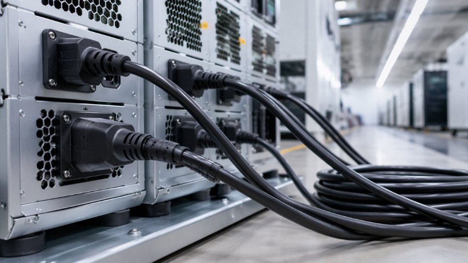
No — and this is probably the most dangerous assumption in everyday electrical practice. A connector that mates correctly tells you nothing about whether the cord can handle the load. The cord still needs to match or exceed the appliance’s rated current draw, carry the correct voltage class for the circuit, and suit the environment it’s operating in. A lightweight 0.75 mm² cord with a C13 plug will seat perfectly into the back of a 13 A industrial UPS — and then overheat under sustained load, because it was sized for a 6 A desk lamp. That’s one of the more consistent root causes of cord fires in small commercial settings: the fit looked right, so nobody questioned anything else.
Physical connector compatibility does not confirm electrical or environmental suitability for a power cord.True
Connector geometry is standardized independently of current rating, insulation grade, and jacket material. A cord that fits the socket may still be undersized for the load, under-rated for the voltage, or made from an incompatible jacket compound for the environment.
Is a thicker power cord always better?
Not always. Going one size up on conductor cross-section — say, using 2.5 mm² where 1.5 mm² would technically suffice — carries no safety penalty and can actually reduce voltage drop on longer runs. But jumping two sizes introduces real practical problems: the cord body gets stiffer and heavier, strain relief fittings sized for the smaller diameter won’t grip correctly, and on pendant or hanging tool applications the added weight puts mechanical stress on the connector interface. Cost adds up in volume procurement too. The target is to match ampacity requirements with an appropriate derating margin, not to use the heaviest conductor available.
What does the cord temperature rating mean, and does it matter indoors?
The temperature rating — 60 °C, 75 °C, 90 °C — describes the maximum continuous operating temperature the insulation can sustain without degrading. It is not an ambient air limit. A cord routed through a tight cable tray, bundled with other conductors, or simply running at its full rated current in a 25 °C room can easily reach its insulation’s thermal ceiling from self-heating alone. Bundling is particularly sneaky here: three cords zip-tied together shed heat much less efficiently than a single cord in free air, and IEC 60364-5-52 correction factors can reduce allowable ampacity by 30–40% depending on grouping configuration. Most indoor installation problems I’ve seen involving discoloured insulation trace back to this, not to high ambient temperatures.
How often should power cords be inspected or replaced?
For commercial and industrial use, IEC 60364-6 recommends periodic formal inspection at intervals of roughly 1–4 years, with the frequency depending on environment severity — a dry server room sits at the low end, an outdoor construction site at the high end. That said, formal inspection schedules don’t replace pre-use checks. In high-flex applications — robotic end-of-arm tooling, portable power tools, floor cleaning equipment — a visual check before each shift is reasonable and catches the majority of developing faults before they become incidents. Any cord showing jacket cracking, discolouration, stiffness that wasn’t there before, or any hint of exposed conductor comes out of service immediately. No exceptions, regardless of where it sits in the inspection calendar.
Are cords from well-known online marketplaces safe to buy?
The marketplace platform itself doesn’t certify anything. Third-party sellers on major platforms are well-documented sources of cords carrying counterfeit or self-declared certification marks — UL, CE, VDE logos printed on the jacket without any corresponding factory surveillance or test record. Verifying a mark takes under two minutes: UL’s database is at ul.com/database, VDE’s at vde.com, and most other bodies maintain equivalent public lookup tools. Search the manufacturer name and cord type. If the listing doesn’t come up, don’t buy it for anything load-bearing. This is a two-minute check that procurement teams routinely skip, and it’s where a meaningful share of substandard cords enter commercial inventory.
What is the difference between a power cord and a power cable?
Standard industry usage draws a clear line. A power cord is a flexible, portable assembly — designed for repeated connection and disconnection, moving with the appliance, subject to handling stress. A power cable is a fixed-installation conductor intended for conduit runs, direct burial, or permanent panel wiring. Different construction standards, different test regimes, different installation codes. Using a flexible power cord as a substitute for fixed wiring is a code violation in most jurisdictions and creates real risk: cords aren’t rated for the fault current levels, overcurrent protection assumptions, or physical protection requirements that govern fixed installations. In practice, the confusion usually surfaces when someone runs a heavy-duty extension cord as a semi-permanent feed to a machine rather than installing a proper circuit — a shortcut that inspectors will flag, and insurers sometimes use to deny claims after a fire.
Can Jinda supply custom cord lengths, jacket colours, or OEM-branded assemblies?
Yes. Jinda’s production infrastructure supports a fairly wide range of customisation: outer diameter, jacket colour to RAL or Pantone specification, conductor cross-section combinations outside standard configurations, and OEM print markings on the jacket surface. Factory-terminated assemblies — complete with customer-specified plug and coupler combinations — are available, and HAR or UL co-certification can be arranged where the target market requires it. For volume OEM procurement, getting Jinda’s technical team involved at the specification stage rather than after samples are in hand tends to avoid the usual back-and-forth over tooling and mark placement.