Undersized cable overheats. That much is obvious. What’s less obvious — until you’re standing in front of a tripped breaker at 2 a.m. or writing off a batch of scrap because insulation degraded six months into a three-year production run — is how many seemingly minor selection errors compound into real downtime and real money. Wrong voltage class, wrong insulation material for the ambient temperature, wrong armor type for the burial depth or mechanical exposure: each one is a liability that doesn’t announce itself until something fails.
Choosing a power cable means matching conductor material and cross-section to your load current and voltage drop limits, selecting an insulation system rated above your operating temperature and environment, specifying the correct voltage class (low, medium, or high), and choosing mechanical protection suited to the installation method — all verified against the relevant IEC or national standard before procurement.
What makes this harder in practice is that the “right” cable rarely exists as a single obvious answer. A 16 mm² copper XLPE cable carrying 110–130 A when buried in average soil might only manage 85–95 A in poorly draining clay, or push past 140 A in dry sandy conditions with active ventilation — the same part number, radically different real-world performance. The sections below work through each selection variable the way you’d actually need to think through it on a live project.
Decode the Voltage Rating: Matching Cable Class to System Voltage
The single most common specification error I see on procurement sheets is a cable ordered by nominal system voltage alone — “we need 10 kV cable” — with no reference to the IEC designation system that actually governs insulation design. That shortcut has caused premature insulation breakdown, unplanned outages, and expensive cable replacements that could have been avoided at the quoting stage.
Understanding U0, U, and Um
IEC uses a three-part voltage designation written as U0/U (Um). Each value does real work:
U0 is the rated voltage from conductor to earth (or to the metallic screen). This is what actually stresses the insulation in normal operation, and it’s the value that drives insulation wall thickness. U is the rated voltage conductor-to-conductor — the phase-to-phase figure most engineers quote first. Um is the maximum system voltage the cable can withstand on a continuous basis, accounting for supply fluctuations and regulation tolerances. It’s not a fault condition; it’s the upper bound of normal operation.
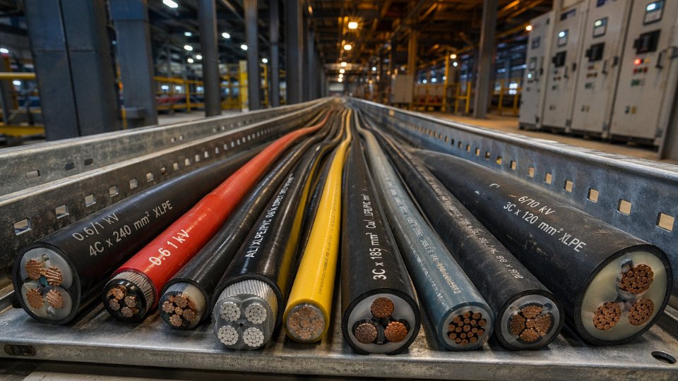
A few worked examples make this concrete. A 0.6/1 kV cable has U0 = 0.6 kV and U = 1 kV — this is your standard LV distribution and motor feeder cable. Step up to 3.6/6 kV and you’re at the lower end of medium voltage, common in industrial plant ring mains. The 6/10 kV designation shows up constantly in urban distribution networks and larger factory substations. 8.7/15 kV is frequently specified in European mining and offshore applications where the neutral earthing arrangement demands a higher U0 for the same nominal system voltage. 26/35 kV cables feed primary substations and large industrial consumers — the insulation wall on an XLPE cable at this rating is typically 9–10 mm, versus roughly 3.4 mm at 6/10 kV, which tells you immediately why getting this wrong is a cost and a safety issue simultaneously.
Voltage Class Bands and Where Each Lives
Low voltage (≤ 1 kV) covers the bulk of building wiring, motor circuits, and control panels — IEC 60502-1 is the governing standard. Medium voltage (1–36 kV) spans industrial distribution, wind farm collector systems, and urban feeder cables, governed by IEC 60502-2 up to 30 kV. High voltage (36–150 kV) moves into transmission and grid interconnection territory, where IEC 60840 applies. Above 150 kV you’re in extra-high voltage, relevant mainly to transmission system operators and large utility projects.
The Transient Overvoltage Margin People Ignore
Nominal system voltage is not your design voltage. Switching transients, capacitor bank operations, and lightning-induced surges can push instantaneous voltage 10–15% above nominal, and in some industrial systems with significant inductive loads, higher still. Specifying a cable rated exactly at nominal system voltage leaves no room. The standard practice — and the IEC philosophy behind Um — is to ensure the cable’s maximum system voltage rating sits comfortably above the highest voltage the network can sustain in normal disturbed operation.
Selecting a power cable rated at exactly the nominal system voltage (without transient overvoltage margin) is compliant with IEC standards.False
IEC voltage designation includes Um specifically to account for continuous maximum system voltages above nominal. A cable must be selected so its Um value exceeds the highest voltage the system can present under normal disturbed conditions, not just the nominal voltage.
How Neutral Earthing Changes the Equation
This is where a lot of procurement managers get caught out. On a solidly earthed neutral system, a phase-to-earth fault is cleared quickly and the healthy phases don’t experience sustained overvoltage. U0 can be sized at roughly 58% of U (the standard phase-to-neutral ratio). On an impedance-earthed or, worse, an isolated neutral system, a single phase-to-earth fault can leave the healthy phases stressed at full phase-to-phase voltage — indefinitely, until protection operates. That means U0 must equal U, pushing you to the next voltage class entirely.
A 10 kV isolated neutral network, for instance, should not be served with 6/10 kV cable. You need 10/10 kV, which in practice means specifying 12/20 kV or 8.7/15 kV rated cable depending on the exact network configuration. Getting this wrong doesn’t cause immediate failure — it causes slow insulation degradation over two to five years, showing up as partial discharge activity before the eventual fault. By then the root cause is hard to trace.
Voltage Selection Decision Table
| Nominal System Voltage | Neutral Earthing | Recommended U0/U Rating | Typical XLPE Wall Thickness |
|---|---|---|---|
| 1 kV | Any | 0.6/1 kV | ~0.7 mm |
| 6 kV | Solidly earthed | 3.6/6 kV | ~2.5 mm |
| 6 kV | Isolated / impedance | 6/6 kV → use 6/10 kV | ~3.4 mm |
| 10 kV | Solidly earthed | 6/10 kV | ~3.4 mm |
| 15 kV | Impedance earthed | 8.7/15 kV | ~5.5 mm |
| 35 kV | Solidly earthed | 26/35 kV | ~9–10 mm |
Thickness ranges depend on conductor size and manufacturer construction; always verify against the specific IEC type test report.
The governing standards to keep on your desk: IEC 60502-1 for cables up to 1 kV, IEC 60502-2 for 1–30 kV extruded insulation cables, and IEC 60840 for the 30–150 kV range. Each sets minimum insulation thickness, test voltages, and qualification requirements. If a supplier quotes you a cable without referencing which part of IEC 60502 it was tested to, ask before you order.
Conductor Sizing: Calculating Current Capacity and Avoiding Thermal Overload
Under-sized conductors are responsible for more cable failures than any other single error — and in most cases, the root cause isn’t ignorance of the formula, it’s skipping the derating steps or treating tabulated ampacity values as if they’re absolute.
The Four Variables That Actually Govern Ampacity
Ampacity — the maximum continuous current a cable can carry without exceeding its rated temperature — is a function of four interacting factors: conductor material, cross-section area, insulation type, and installation method. Change any one of them and the number shifts, sometimes dramatically.
Conductor material matters because of resistivity. Copper sits at 1.72 × 10⁻⁸ Ω·m at 20°C; aluminum is 2.82 × 10⁻⁸ Ω·m, roughly 64% higher. In practice that means an aluminum conductor needs to be one to two size steps larger than copper to carry the same current — so the upfront material cost difference narrows considerably once you’re buying 120 mm² or 150 mm² aluminum versus 95 mm² copper.
Insulation type sets the thermal ceiling. XLPE and EPR both tolerate 90°C continuous operating temperature; PVC is typically limited to 70°C. That 20°C gap translates directly to higher allowable current density, which is why XLPE has largely displaced PVC in industrial power feeders over the last two decades or so. Installation method — whether you’re in free air, in conduit, direct buried, or laid in a cable tray — governs how efficiently heat dissipates away from the conductor. Free air gives the best thermal path; direct burial into soil with high thermal resistivity is often the worst.
Working Through Derating: Where Projects Go Wrong
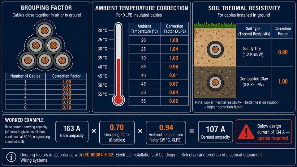
The IEC 60364-5-52 reference tables give base ampacity values under specific reference conditions (30°C ambient for air installations, 20°C for ground). Real installations almost never match those conditions, so derating factors must be applied multiplicatively.
A few realistic examples of what to expect:
- Grouping factor: Six cables laid together in a trefoil bundle — a common arrangement in cable trays — applies roughly a 0.70 correction factor. Mutual heating is the culprit. This alone cuts theoretical ampacity by 30%.
- Ambient temperature: At 35°C ambient against a 30°C baseline, a typical correction factor for XLPE cable is around 0.94. In a hot process area running 45–50°C, that factor can fall to 0.82–0.86. Seasonal effects matter too — a cable tray on a rooftop in summer can see ambient temperatures that shave 10–15% off ampacity versus the winter baseline.
- Soil thermal resistivity: For direct buried cables, soil thermal resistivity of 1.2 K·m/W (dry, sandy soil) can reduce ampacity by roughly 10–15% compared to the 1.0 K·m/W reference condition. Wet, well-compacted clay is more forgiving; dry desert sand is not.
A Realistic Sizing Walk-Through
Take a 3-phase 400 V motor load: 75 kW rated output, power factor 0.85, efficiency 0.95. The design current works out to roughly 134 A — calculated as 75,000 ÷ (√3 × 400 × 0.85 × 0.95).
From IEC 60364-5-52 tables, 35 mm² copper XLPE cable in free air carries approximately 163 A under reference conditions. Apply a grouping factor of 0.70 (six cables bundled) and a temperature correction of 0.94 at 35°C ambient: 163 × 0.70 × 0.94 ≈ 107 A. That’s below the 134 A design current — so 35 mm² is actually inadequate in this installation. Step up to 50 mm², repeat the calculation, and you clear the requirement with reasonable margin.
This is exactly the sequence that gets skipped when engineers pull the cross-section straight from a catalog without accounting for installation specifics.
Minimum Safe Size vs. Economic Cross-Section
These are two different decisions and they don’t always converge on the same answer.
Minimum safe cross-section is purely a thermal limit — the smallest conductor that won’t overheat under worst-case operating and derating conditions. Economic cross-section, by contrast, optimizes lifecycle cost by reducing resistive losses. For a lightly loaded feeder that runs intermittently, the thermal minimum might be 16 mm²; but if that feeder runs at 80% load factor for 20 years, the energy savings from stepping up to 25 mm² or 35 mm² may well pay back the extra copper cost within three to five years, depending on local electricity tariffs and load profile. In high-utilization industrial settings — continuous process lines, pumping stations, compressor feeders — specifying one or two sizes above thermal minimum is worth costing out.
Short-Circuit Withstand: The Calculation Most Designers Underweight
Thermal sizing for normal operation is only half the story. The conductor must also survive the fault current that a protection device will clear. The adiabatic equation covers this: I²t = k²S², where S is cross-section in mm², t is fault clearing time in seconds, and k is a material/insulation constant — 143 for copper with PVC insulation, 176 for copper XLPE.
For a 10 kA prospective fault current with a 1-second clearing time (a conservative but not unusual assumption where upstream protection coordination is unclear): S ≥ (10,000 × √1) ÷ 176 ≈ 56.8 mm² minimum for copper XLPE. A 50 mm² cable selected purely on ampacity would fail this check. The minimum safe conductor in this scenario is 70 mm².
IEC 60364-5-52 provides the internationally recognized reference tables for cable ampacity and installation correction factors used in low-voltage system design.True
IEC 60364-5-52 is the established IEC standard covering selection and erection of electrical equipment, including wiring systems, and is the primary normative reference for ampacity tables and grouping/temperature correction factors in LV cable sizing across most jurisdictions outside North America.
Jinda’s engineering team provides free ampacity calculation support for project inquiries — useful when you’re dealing with unusual installation geometries, mixed burial conditions, or need to reconcile IEC tables against a specific national code variant.
Conductor Material Compared: Copper vs. Aluminum in Real Project Conditions
The copper-versus-aluminum debate comes up on almost every large cable procurement, and it rarely has a clean universal answer. Both materials are entirely legitimate choices — the right call depends on installation type, run length, termination practice, and what the project budget actually looks like over a 20- to 30-year service life.
The Core Physical Differences Matter More Than You’d Think
Copper’s resistivity sits at 1.72 × 10⁻⁸ Ω·m at 20°C. Aluminum comes in at 2.82 × 10⁻⁸ Ω·m — about 64% higher. That gap directly drives everything else in the comparison. To carry the same current load, an aluminum conductor needs roughly 1.6× the cross-sectional area of a copper equivalent. In practical terms, a 95 mm² aluminum conductor approximates a 50–70 mm² copper conductor, depending on installation method, ambient temperature, and grouping factors. That range matters: a poorly ventilated cable tray or high ambient temperature pushes you toward the larger end of that aluminum sizing band.
Density tells the other half of the story. Copper runs around 8,900 kg/m³; aluminum is roughly 2,700 kg/m³. A 95 mm² aluminum conductor cable will be substantially lighter than its copper counterpart, which is why overhead distribution lines and long-span aerial bundled conductors almost universally use aluminum. Tensile strength slightly favors copper for flexible and repeatedly-flexed applications, and aluminum’s thermal expansion coefficient (approximately 23 × 10⁻⁶ /°C vs. copper’s 17 × 10⁻⁶ /°C) creates real consequences at terminations if the connection hardware isn’t rated for it.
What Total Cost of Ownership Actually Looks Like
Raw aluminum typically costs 30–50% less per kilogram than copper, though that spread fluctuates with commodity markets and you should never lock in a project budget assuming the current spread holds. The material saving sounds decisive until you account for what aluminum requires downstream.
Aluminum oxidizes quickly on exposed surfaces, forming a high-resistance oxide layer that causes joint heating and, over years, connection failure. Every aluminum termination needs anti-oxidant compound applied during installation — it’s a consumable that’s easy to skip and frequently is skipped, especially on site with deadline pressure. Beyond that, aluminum requires larger conduit runs (because 95 mm² is physically bigger than 70 mm² copper), heavier and more expensive compression lugs, and bi-metal connectors wherever aluminum terminates into copper equipment buswork. On a large substation project with dozens of terminations, those hardware costs accumulate.
The honest calculation for a long underground HV feeder — say, 2–5 km connecting an industrial substation — often still favors aluminum once you run the numbers properly. The conductor cost saving on large cross-sections (240 mm² and above) tends to outweigh the termination hardware premium, especially if trench and conduit costs are already in the budget and the slightly larger diameter is not a constraint.
Where Each Material Belongs
Aluminum wins economically on long-distance underground feeders, overhead distribution, and large MV or HV substation interconnects where conductors are 95 mm² and above. Weight is a genuine advantage in aerial applications and seismically active regions where cable tray loads matter.
Copper is preferred — and sometimes mandatory — in flexible cables, motor drop leads, marine and offshore installations (salt-air accelerates aluminum oxidation significantly), control and instrumentation wiring, and any confined-space installation requiring tight bending radii. Most shipbuilding classification rules explicitly require copper. So do many mining cable standards for the same reason.
Aluminum conductors require anti-oxidant compound at all joints and terminations to prevent high-resistance oxide layer formation.True
Aluminum oxide (Al₂O₃) forms rapidly on exposed aluminum surfaces and has significantly higher electrical resistance than the base metal. This is well-established in IEC and IEEE wiring practice, and failure to apply anti-oxidant compound is a documented cause of overheating at aluminum terminations.
Creep, Oxidation, and How to Manage Them
Aluminum creep — the slow plastic deformation under sustained mechanical stress — is real but manageable with the right hardware. Proper compression lugs specified for aluminum (not general-purpose crimped lugs), correct torque values, and periodic inspection on large conductors address this. Bi-metal transition connectors at the equipment interface handle the expansion differential. These aren’t exotic requirements; they’re standard practice on any well-run aluminum cable installation. The problem is usually not the aluminum — it’s aluminum installed with copper-rated hardware by someone who assumed the difference didn’t matter.
Jinda manufactures both copper and aluminum conductor cables across its production bases, covering low-voltage through high-voltage ranges, and the engineering team can work through cross-section equivalence and termination requirements for a specific project before the procurement decision is finalized. That kind of pre-order technical review tends to catch the conduit sizing and hardware mismatches before they become site rework.
Insulation and Sheathing Selection: PVC, XLPE, EPR, and Beyond
The conductor handles current. The insulation determines whether that current stays where it belongs — and for how long, under what conditions. Pick the wrong insulation system and you’re not just looking at a derating problem; you’re looking at accelerated degradation, premature failure, or in a fire scenario, smoke that kills before flames do.
PVC, XLPE, and EPR: The Three Workhorses
PVC (polyvinyl chloride) is the default for general low-voltage work, and it earns that position on cost and processability alone. Continuous conductor temperature limit sits at 70°C, which is adequate for most commercial building circuits and light industrial distribution panels. The limitation shows up fast in high-load or high-ambient environments — a cable tray running through a boiler room, a feeder next to a furnace exhaust duct. Once the conductor temperature climbs consistently toward that 70°C ceiling, PVC softens, insulation integrity degrades over years rather than decades, and you start seeing insulation resistance trending down during routine testing. In practice, PVC cable also has a harder time passing modern flame propagation requirements without additives, and its combustion byproducts include hydrogen chloride, which is corrosive to electronics and genuinely dangerous in confined spaces.
XLPE (cross-linked polyethylene) is the dominant choice for medium- and high-voltage cables, and increasingly for heavy LV feeders. The cross-linking step is the critical difference: heat and a chemical or irradiation process create covalent bonds between adjacent polymer chains, converting what was a thermoplastic into a thermoset. Practically, that means the material doesn’t soften under heat the way PVC does. Continuous rating reaches 90°C, and short-circuit withstand goes up to around 250°C — a margin that genuinely matters when a fault occurs downstream and your protection takes two or three cycles to clear. XLPE also has lower dielectric losses than EPR, which becomes significant at medium and high voltage over long cable runs.
EPR (ethylene propylene rubber) sits at the same 90°C continuous rating as XLPE but behaves differently mechanically. It stays flexible at temperatures well below freezing — down to roughly −40°C in some formulations — where XLPE stiffens and becomes vulnerable to cracking during installation or flexing. That’s why EPR dominates in offshore platforms, subsea umbilicals, and nuclear plant instrumentation cables, where you’re combining low-temperature handling, high mechanical stress, and a regulatory requirement for documentation that traces every material lot. EPR costs more per meter than XLPE, usually meaningfully so, and that gap pushes most onshore projects back toward XLPE unless the flexibility or nuclear qualification is genuinely needed.
Specialty Insulation for the Edge Cases
Silicone rubber handles continuous temperatures up to around 180°C and is the go-to for wiring inside industrial ovens, kiln sensor leads, and fire-survival circuits in steel plants. It’s expensive, mechanically soft, and frankly easy to damage during installation if your crew isn’t used to handling it. Fluoropolymers — PTFE and FEP primarily — are specified where aggressive chemical exposure is unavoidable: pharmaceutical plants, chemical dosing rooms, battery manufacturing lines. Mineral insulated copper-clad (MICC) cable takes fire survival to its logical extreme; the magnesium oxide insulation and copper sheath will maintain circuit integrity at temperatures that would destroy any polymer-insulated alternative. MICC is rigid, termination requires trained technicians, and the material cost is high, but for a hospital emergency circuit or a smoke extract fan feed, there’s often no qualified substitute.
Sheathing: The Last Line of Defense
The outer sheath doesn’t contribute to insulation in the electrical sense, but it determines how long the insulation survives its installation environment.
PVC ST2 sheathing is standard for most indoor and duct-routed cables — cost-effective, good abrasion resistance, straightforward to install. Direct burial changes the equation. HDPE sheathing absorbs essentially no moisture, resists soil chemicals better than PVC, and handles the mechanical abuse of direct burial or duct pulling in conduit with sharp-edged backfill. A cable installed in coastal reclaimed land with saline groundwater and PVC sheathing rather than HDPE will show measurable insulation degradation within a handful of years; the same cable with HDPE sheathing runs twenty-plus years without issue, all else equal.
LSZH (low smoke zero halogen) sheathing — and in well-specified projects, LSZH insulation through the whole cable construction — is now contractually required in most tunnels, metro systems, data centers, airports, and public assembly buildings. The reasoning is straightforward: in a PVC cable fire, HCl gas incapacitates people before heat does, and it corrodes server racks and switchgear even when cables outside the fire zone are only lightly affected.
LSZH cables produce significantly less toxic and corrosive smoke than PVC cables in fire conditionsTrue
LSZH (low smoke zero halogen) compounds are formulated without halogenated additives; combustion produces primarily CO2 and H2O rather than hydrogen halide gases. This is verified by IEC 61034 smoke density testing and IEC 60754 halogen acid gas emission testing, both of which LSZH cables must pass to carry the designation.
Fire Performance Standards: What Each Certificate Actually Means
Three IEC standards govern fire performance, and specifiers frequently confuse them or treat them as interchangeable — they aren’t.
IEC 60331 tests circuit integrity under fire: the cable must continue to carry current at rated voltage while exposed to a 750°C or 830°C flame for 90 minutes (test details vary by part). This is what a fire-survival cable must have. IEC 60332-3 tests flame propagation in a bundled installation — it tells you whether fire will travel along a cable tray and spread to remote areas. IEC 61034 measures smoke density. A cable can pass 60332-3 but still produce dense black smoke (failing 61034), which is why metro and tunnel specs increasingly require compliance with all three. In competitive tender situations it’s worth reading the specification carefully; “fire resistant cable” in a procurement document sometimes means only 60331, sometimes all three, and the cable cost difference between those interpretations is real.
Selection Matrix: Insulation and Sheath by Environment
| Environment / Requirement | Recommended Insulation | Recommended Sheath | Key Standard(s) |
|---|---|---|---|
| General LV indoor / commercial | PVC | PVC ST2 | IEC 60227 |
| Heavy LV feeders, high load | XLPE | PVC ST2 or LSZH | IEC 60502-1 |
| MV/HV distribution | XLPE | HDPE or PVC | IEC 60502-2, IEC 60840 |
| Direct burial, moist / saline soil | XLPE | HDPE | IEC 60502-2 |
| Offshore / low-temperature flex | EPR | CSP or LSZH | IEC 60092 series |
| Nuclear instrumentation | EPR | LSZH | IEC 60092, plant-specific |
| Tunnel / metro / data center | XLPE or EPR | LSZH | IEC 60332-3, IEC 61034 |
| Fire-survival circuit | MI or silicone | Copper / LSZH | IEC 60331 |
| High chemical exposure | PTFE / FEP | PTFE or stainless overbraid | Application-specific |
| Extreme continuous heat (>120°C) | Silicone rubber | Silicone or glass braid | IEC 60245 |
The matrix is a starting point, not a final answer. Soil thermal resistivity, installation grouping, ambient temperature corrections, and local authority approvals all layer on top. But getting the insulation system wrong from the outset — specifying PVC into a 90°C ambient, or skipping LSZH in a cable basement feeding a public building — creates problems that can’t be fixed without pulling and replacing cable.
Armoring, Screening, and Mechanical Protection: Choosing the Right Cable Construction
Not every cable needs armor. That’s the first thing to get straight — over-specifying mechanical protection adds cost, weight, and installation labor, while under-specifying it leads to damaged insulation, ground faults, and in the worst cases, fire. The decision comes down to three questions: what mechanical stresses will the cable actually see, what electrical interference environment is it in, and what’s the consequence of a failure?
Armoring Types and When to Use Each
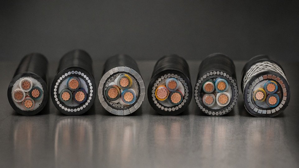
Steel wire armoring (SWA) is the workhorse for direct burial and cable tray installations. Individual galvanized steel wires laid helically over the inner sheath give you both crush resistance and meaningful tensile strength — typically 5–15 kN depending on cable diameter and core count, sometimes higher on larger multicore designs. Radial crush resistance runs roughly 450–600 N/cm on properly constructed cables. That matters in direct burial because backfill compaction, especially on clay-heavy or stony ground, creates sustained lateral loads that unarmored cable simply can’t handle long-term.
Steel tape armoring (STA) uses two overlapping steel tapes instead of wires. It handles crush loads well but offers almost no tensile strength. Use it in ducts or conduits where the installation provides mechanical routing support and you mainly need protection against incidental impact or rodent damage. Don’t spec STA for a pull through a long conduit run — the cable will take the tensile load through the conductor and inner sheath, which is not where you want it.
Single-core cables are a different problem entirely. Run steel wire armor around a single-core AC cable and you’ve created a shorted turn around the conductor — eddy current losses become significant, the armor heats up, and in large cross-sections the efficiency penalty is real enough to matter on energy costs. Aluminum wire armoring (AWA) solves this because aluminum’s higher resistivity drastically reduces induced currents. AWA is the standard specification for single-core MV cables for exactly this reason.
For rodent-prone environments — underground rural runs, certain parts of Southeast Asia and sub-Saharan Africa where rodent pressure is genuinely severe — double steel tape armoring offers a harder outer surface that most rodents won’t chew through. It’s heavier and less flexible than SWA, but on a fixed buried route that’s rarely a problem.
Electrical Screening on Medium-Voltage Cables
On any MV cable above roughly 3.6/6 kV, a metallic screen isn’t optional. It’s a safety requirement, and treating it as an upgrade is a specification error.
The screen — copper tape or copper wire applied over each core’s insulation — does three things simultaneously: it constrains the electric field to the insulation layer, prevents dangerous surface voltages on the cable outer surface, and provides a defined low-impedance return path for fault current. Without it, the electric field distribution becomes unpredictable, and touch voltage on the cable surface can be lethal under certain fault conditions.
Unscreened cable is acceptable for medium-voltage distribution systems above 6 kVFalse
IEC 60502 and most national grid codes require metallic screening on MV cables above 3.6/6 kV. Operating without screening creates uncontrolled electric field distribution and unsafe surface voltages — it is a safety violation, not a cost-saving option.
Individual core screening is standard practice for MV multicore cables. Each core gets its own copper tape or wire screen, bonded and earthed at one or both ends depending on the system design. Collective screening — a single screen around all cores together — is common in LV instrumentation and control cables where you need shielding against EMI rather than voltage stress management. Don’t confuse the two applications; they solve different problems.
Flexible Conduit vs. Armored Cable for Machine Connections
At machinery connection points — motors, pumps, compressors with significant vibration — there’s a genuine trade-off. Armored cable (SWA or braided stainless armor) gives permanent protection and needs no additional raceway, but replacing it after mechanical damage means cutting out and rejoining a fixed run. Flexible conduit with unarmored cable inside lets you swap the cable without disturbing the conduit, which matters on production equipment where minimizing downtime on a maintenance call is worth something. In my experience on food processing and packaging lines, maintenance crews strongly prefer the conduit approach because they can carry a replacement cable length without pre-measuring.
Special Environments
Submarine cables need a lead sheath or corrugated aluminum sheath under the armor to block moisture ingress — XLPE alone is not a long-term moisture barrier under hydrostatic pressure. Chemical plant tray installations call for a polyurethane (PUR) or chlorosulfonated polyethylene (CSP) outer sheath rather than standard PVC, which degrades in hydrocarbon splash zones faster than most people expect. Festoon cables on overhead crane systems are a completely different construction: high-flex bunched stranding (often Class 6 per IEC 60228), an abrasion-resistant outer sheath, and no rigid armor — because armor and continuous flexing are fundamentally incompatible. A crane festoon cable that someone has substituted with standard SWA will show conductor fatigue fractures within months.
Match the construction to the actual installation environment. The cable datasheet tells you what the cable can do; your site survey tells you what it needs to do. The gap between those two is where failures happen.
Installation Environment Checklist: Underground, Aerial, Tray, and Hazardous Area Rules
Where a cable lives determines what it needs to be. Voltage class, cross-section, insulation — all of that work gets undone if the construction doesn’t match the installation environment. This is where specification errors actually happen on real projects: a tray installation treated like open-air, a direct burial without armoring, a hazardous area terminated with an uncertified gland. The following environment-by-environment breakdown is meant to catch those mistakes before they reach site.
Direct Burial Underground
Minimum cover depth runs 0.6 m for low-voltage cables in most jurisdictions, stepping up to 0.9–1.0 m for medium-voltage (1–36 kV) routes, though local regulations vary enough that you should always confirm with the authority having jurisdiction — some industrial sites or road crossings require 1.2 m regardless of voltage class.
Cable construction for direct burial should be SWA (steel wire armored) or, where ground movement and corrosion are concerns, HDPE-sheathed armored construction. Unarmored cable in a trench is a risk that usually surfaces during a later excavation by a contractor who ignores the marker tape — and it will happen eventually.
Proper bedding matters more than most installation teams admit. 100 mm of sharp-sand below and 100 mm above the cable, compacted, then a layer of selected backfill, then the marker tape at 250–300 mm below finished grade. Skipping the sand and relying on native soil increases the thermal resistivity of the immediate cable environment, which directly reduces ampacity.
For any copper cable above roughly 50 mm² — and certainly anything above 95 mm² — a soil thermal resistivity survey is worth doing. Soil resistivity varies widely, from about 0.7 K·m/W in moist clay to over 2.5 K·m/W in dry sandy soil. That difference can shift the cable’s continuous current rating by 15–25%, which is enough to force a conductor size increase if you got the survey wrong.
Cable Tray and Ladder Installations
Ventilated ladder tray in open air is the best-case scenario — cables can usually be rated at full ampacity per IEC 60364-5-52. Move to perforated tray and you lose airflow around the lower layers; apply a 15–20% derating as a starting point. Bundle cables touching each other in a single layer and the derating becomes substantial — Table B.52.20 in IEC 60364-5-52 makes this clear, and most engineers underestimate how steep the correction factors get when you have more than three or four touching cables.
Tray material selection is often treated as a purchasing afterthought, but it matters. Galvanized steel is standard for most indoor industrial environments. Aluminum tray is lighter and sufficient for many applications, but incompatible with alkaline wash-down environments found in food processing. FRP (fiberglass reinforced plastic) tray is the right call for chemical plants and coastal facilities where steel corrodes faster than it should — the upfront cost premium is real, but it’s smaller than a tray replacement job five years in.
Perforated cable tray requires derating compared to ladder/ventilated tray installationsTrue
Perforated trays restrict airflow around cables more than open ladder trays, requiring derating factors per IEC 60364-5-52 Table B.52.20 to prevent thermal overload of conductors.
Aerial and Self-Supporting Overhead
ABC (aerial bundled cable) constructions use XLPE insulation and an integrated messenger wire to handle the mechanical span load. Minimum conductor size for self-supporting spans is typically 16 mm² for short spans up to roughly 40 m, but longer spans or ice-loading zones require a proper structural calculation — the mechanical tension in the messenger wire at maximum sag and maximum ice load governs, not just the electrical current.
UV-stabilized outer sheath is not optional for outdoor aerial work. Standard PVC sheaths degrade visibly within three to five years of UV exposure in high-sun climates, and the degradation isn’t just cosmetic — it leads to sheath cracking and moisture ingress. Specify UV-stabilized HDPE or UV-resistant PVC and get confirmation from the manufacturer that it’s been tested to IEC 62440 or equivalent.
Wind and ice load calculations for span design follow IEC 60826 or local equivalent. In practice, the ice load assumption is where projects in northern climates get into trouble: using a temperate-climate assumption in a region that gets freezing rain events leads to messenger wire failures within the first decade of service.
Hazardous Areas: ATEX and IECEx Zones
A common misconception worth addressing directly: the cable itself does not require ATEX or IECEx certification for Zone 1 or Zone 2 gas environments. The cable glands and termination components are what must be certified, since they form part of the Ex-e or Ex-d enclosure. That said, mineral-insulated (MI) cables and fire-resistant cables are routinely specified for Zone 1 circuits on process plants, because circuit integrity during a fire event matters as much as explosion protection — a cable that fails during the incident is worse than no cable at all.
Zone 0 dust environments introduce a different requirement: the outer sheath must not generate or accumulate electrostatic charge. This rules out some standard PVC compounds and requires testing to IEC 60079-32-1. It’s a specification point that gets missed surprisingly often on dust-handling facility projects.
Marine and Offshore
IEC 60092 governs shipboard cables. For passenger vessels specifically, halogen-free, fire-resistant construction is mandatory — burning PVC produces hydrogen chloride, which is toxic in enclosed spaces and corrosive to electronics. Offshore cables also need to handle continuous seawater spray, oil contamination in engine rooms, and mechanical impact from equipment movement, which pushes the construction toward armored, oil-resistant outer sheathed types with tinned copper conductors to resist corrosion at terminations.
Conduit and Duct Systems
Cables in ducts run hotter than directly buried cables in the same soil, because the air gap and duct wall add thermal resistance. Duct fill ratio should stay under 40% of the duct cross-section — beyond that, heat dissipation deteriorates noticeably and you’re making optimistic assumptions about the ampacity.
Pulling tension during installation is the other constraint people underestimate. Maximum pulling tension is typically in the range of 50 N/mm² of conductor cross-section for copper and around 30 N/mm² for aluminum. Exceed those limits on a long duct run with bends and you risk deforming the conductor or damaging the insulation without any visible external sign. Minimum bend radius for armored cables is generally 12–15 times the overall cable diameter; going tighter risks kinking the armor and crushing the insulation beneath it.
International Standards and Certifications: IEC, BS, UL, and Regional Compliance
Getting the cable spec right technically means nothing if the product doesn’t satisfy the certification requirements of your destination market. Re-procurement mid-project — because a customs authority or end-client engineer flags non-compliance — typically costs two to four times the original cable value once you factor in demurrage, re-testing delays, and schedule penalties. This section is a working reference, not an overview.
The IEC Framework: Where Most International Projects Start
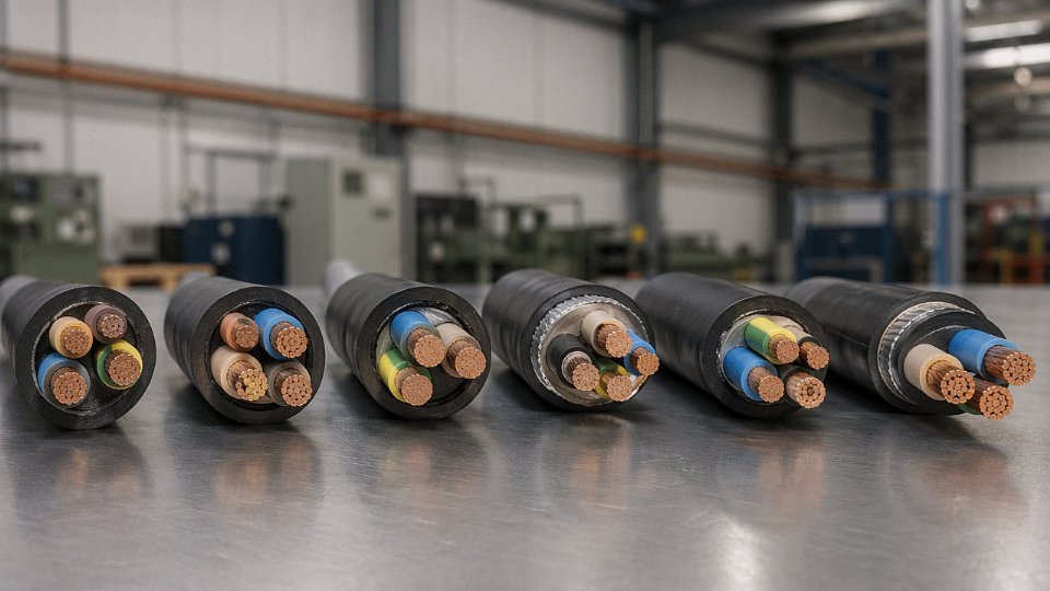
IEC is the baseline for the majority of international tenders, particularly across the Middle East, Africa, Southeast Asia, and increasingly Latin America. The core documents you’ll encounter on any low-to-medium voltage project are IEC 60228, which defines conductor classes (Class 1 solid through Class 6 flexible stranded), and IEC 60502, which governs extruded insulation cables from 1 kV up to 30 kV — construction, test voltages, partial discharge limits, the works. If your tender spec just says “IEC compliant” without citing a document number, push back and ask which one; that phrase alone is not a specification.
For high-voltage work (36–150 kV), IEC 60840 applies, and above 150 kV you’re into IEC 62067 territory. These impose substantially more demanding type test requirements, including long-duration prequalification tests that can run 12 months — a detail that catches procurement teams off guard when they’re under schedule pressure.
Fire performance is its own family of standards. IEC 60331 tests circuit integrity under flame; IEC 60332 covers flame propagation in bunched installations; IEC 61034 measures smoke density. A cable spec that requires all three simultaneously is asking for something meaningfully more expensive than standard XLPE — and rightly so in tunnels, hospitals, or public buildings.
Marine and offshore installations fall under IEC 60092, which has its own insulation and sheathing requirements tied to shipboard temperature and fire risk classifications.
BS Standards: Still Mandated Across Former Commonwealth Markets
Don’t assume IEC replaces BS everywhere. Specification engineers in Nigeria, Kenya, Malaysia, and parts of the Gulf frequently still write BS 5467 (armored XLPE, 600/1000 V) or BS 6724 (LSZH armored equivalent) into their tender documents — sometimes alongside IEC, which creates a dual-compliance headache. BS 7671, the UK wiring regulations, isn’t a cable manufacturing standard per se, but it references installation methods and minimum cable ratings that indirectly constrain what you can supply. If a UK-trained consultant is writing the project spec, expect BS language regardless of where the installation actually sits.
North American Projects: A Different Ecosystem Entirely
The US and Canadian markets use a separate standard architecture that doesn’t map cleanly onto IEC. UL 44 covers thermoset-insulated conductors (XHHW-2 being the common XLPE equivalent), UL 83 covers thermoplastic types (THW, THWN), and UL 1072 governs medium-voltage cables. NEC Article 310 is where engineers look up ampacity tables — but those tables are built around AWG and kcmil sizing, not mm². A 4/0 AWG conductor is roughly 107 mm², a 350 kcmil is roughly 177 mm²; conversion charts exist but always verify, because rounding errors in conductor sizing have consequences.
Regional Standards You’ll Hit in Practice
| Market | Primary Standard | Key Quirks |
|---|---|---|
| Australia / New Zealand | AS/NZS 5000 | Often requires local third-party mark |
| South Africa | SANS 1507 | Closely mirrors IEC but with local test requirements |
| Russia / CIS | GOST R | Separate conductor class designations; metric sizing |
| China domestic | GB/T series | Not interchangeable with IEC without testing |
Third-Party Type Test Reports vs. Self-Declaration
On major infrastructure tenders — power utilities, government-funded grid projects, EPC contractors with strict QA clauses — a manufacturer’s self-declaration of IEC conformity is often not enough. Buyers increasingly require independent type test reports from accredited laboratories: KEMA (now KEMA-DEKRA), CESI in Italy, CPRI in India, or equivalent bodies. These reports must match the exact cable construction being supplied, not a similar one. In practice, this means suppliers who’ve done the type tests on a 16 mm² 0.6/1 kV XLPE cable cannot automatically claim those results cover a 25 mm² variant — the test is construction-specific.
Type test reports from accredited third-party laboratories are interchangeable between different cable cross-sections of the same design seriesFalse
Type test reports are specific to the tested construction. A different conductor cross-section, even within the same insulation and sheathing system, requires its own type test or a documented technical justification accepted by the certifying body and the client's engineer.
Jinda’s Certification Position on International Projects
Jinda’s cables are produced in compliance with IEC 60228, IEC 60502, and relevant BS and IEC fire performance standards, supported by in-house laboratory facilities capable of routine and sample testing — conductor resistance, insulation resistance, voltage withstand, partial discharge for MV cables, and mechanical tests on armoring and sheaths. For export projects into the Middle East, Africa, and Southeast Asia, the company maintains the type test documentation and third-party test reports that tendering clients and EPC contractors require. Where a project calls for market-specific compliance — SASO for Saudi Arabia, SONCAP for Nigeria, or similar — that needs to be confirmed at the inquiry stage, not after production. Experienced procurement managers know to raise it in the RFQ; don’t leave it to the approval stage.
Frequently Asked Questions About Power Cable Selection
How far can a power cable run before voltage drop becomes a problem?
The standard guideline under IEC 60364 is to keep voltage drop below 3–5% of nominal voltage for low-voltage distribution circuits. The 5% figure is a hard ceiling for most industrial systems; 3% is what you actually want to target on circuits feeding sensitive equipment or motor starters.
The formula engineers should have memorized: ΔV = √3 × I × L × (R·cosφ + X·sinφ)
Where L is the one-way route length in km, R is conductor resistance in Ω/km, X is reactance in Ω/km, and cosφ is the power factor of the load. In practice, for a 400 V three-phase circuit running 200 m at 80 A with a 0.85 power factor, you’ll almost certainly find that the cross-section dictated by ampacity alone — say, 16 mm² copper — drops more voltage than the system can tolerate, and you need to jump to 25 or even 35 mm². That’s one or two standard steps up the IEC 60228 size ladder, which is a common outcome for any run above roughly 100 m at meaningful load. Don’t size for thermal capacity and then forget to check the voltage end of things. It’s a surprisingly frequent design gap.
Can I use single-core cables instead of a three-core cable for a three-phase circuit?
Yes, and it’s done routinely for larger cross-sections where three-core cables become impractically heavy and stiff — anything above about 150–185 mm² is where this usually makes sense. The critical constraint: single-core cables in a three-phase circuit must be laid in trefoil formation, and they must use aluminum wire armoring (AWA), not steel wire armoring (SWA).
Steel is ferromagnetic. A single-core cable carrying AC current induces a magnetic field in steel armoring, which generates eddy current losses, heats the armor, and reduces effective current-carrying capacity — sometimes significantly. AWA eliminates this. Bonding and earthing of the screen and armor also require attention on long runs; single-point bonding works for shorter lengths, but cross-bonding or solid bonding at both ends becomes necessary beyond roughly 500 m to manage induced sheath voltages safely.
How do I read cable designation codes like N2XY, NA2XY, or NYFGY?
These follow the IEC/VDE-based German designation system, and once you decode the logic it becomes reasonably readable. In N2XY: N = German standard (VDE), 2X = XLPE insulation, Y = PVC outer sheath. The absence of an “A” after N means copper conductor; NA2XY means aluminum conductor. An “F” in the code indicates flat steel wire armoring; “SE” or “2Y” variants indicate different sheath formulations. “G” typically denotes green-yellow earth conductor inclusion.
It’s worth knowing that not every manufacturer interprets the middle characters identically, so always cross-reference the designation against the actual technical datasheet — especially on dual-certified cables built for export.
What is the difference between a cable rated 0.6/1 kV and one rated 1/1 kV?
The first number is U₀ — the rated voltage from conductor to earth. The second is U — conductor to conductor. A 0.6/1 kV cable is designed for solidly earthed neutral systems, which is the standard TN or TT arrangement in most industrial plants. A 1/1 kV cable is specified for unearthed (IT) or high-impedance earthed systems, where a phase-to-earth fault doesn’t immediately cause a trip and the cable must tolerate full phase-to-phase voltage appearing across its insulation to earth for an extended period.
Fitting a 0.6/1 kV cable into an unearthed system is a genuine safety error, not just a paperwork issue. The insulation stress can cause premature breakdown, and in the worst case the failure mode is not benign.
A 0.6/1 kV cable is interchangeable with a 1/1 kV cable in all three-phase systems.False
The U₀ rating governs insulation stress under earth fault conditions. In unearthed or high-impedance earthed (IT) systems, a 0.6/1 kV cable is inadequately rated because the full phase-to-phase voltage can appear across the insulation to earth during a fault. A 1/1 kV cable is required in such systems.
How long can a cable be stored before installation?
Properly stored — indoors, off the ground, shielded from UV, on original drums, in a temperature range of roughly 0–35°C — cables with XLPE insulation can realistically sit for 10 years or more without performance degradation. IEC 60502 does not impose a mandatory shelf-life limit on XLPE-insulated cables. PVC-insulated cables are somewhat more forgiving of minor temperature excursions, though extended cold storage below -10°C can cause sheath brittleness that shows up when you start unreeling.
What actually causes storage failures is almost never time — it’s moisture ingress through unsealed drum ends, UV cracking on cables left outside, or physical damage from drums stored on their side and deforming under their own weight. Keep end caps on, log the storage date, and inspect the outer sheath visually before installation. Rotate drums that have been stationary for more than two or three years to prevent flat-spotting on larger constructions.
Does Jinda offer custom cable designs for non-standard requirements?
Yes. With five production bases across China and an in-house R&D function, Jinda manufactures custom constructions including non-standard cross-sections outside the IEC 60228 range, special compound sheath formulations for aggressive chemical environments, dual-certified cables built to meet two regional standards simultaneously, and cables with unusual voltage class combinations for specific transmission or traction applications. This matters most on projects where a single datasheet specification doesn’t map cleanly onto a standard catalogue product — which happens more often than procurement managers expect on greenfield industrial or infrastructure work. Project inquiries typically receive a technical response within 24 hours.
Procurement and Supplier Qualification: Avoiding Counterfeit and Substandard Cable
The cables arrive on site, the drums look right, the labeling matches the PO — and then six months into service, a joint runs hot and you’re chasing a fault through 2 km of buried trench. In a lot of those cases, the root cause traces back to a conductor that was never the size it claimed to be.
The Scale of the Problem Is Larger Than Most Buyers Expect
Industry estimates suggest 10–25% of cables in certain emerging markets contain substandard conductor cross-sections, with actual copper content running 10–20% below declared values.True
This range is consistent with findings reported by industry bodies including the IEC Conformity Assessment System and multiple utility procurement audits in Southeast Asia, the Middle East, and Sub-Saharan Africa. The exact proportion varies significantly by market and procurement channel.
A 16 mm² conductor with actual copper fill closer to 13–14 mm² will carry roughly the same current on paper but will run 15–25°C hotter in steady-state operation, depending on load factor and installation method. Over time that means accelerated insulation degradation, premature joint failure, and in worst cases, fire. The economics are obvious — copper is the single largest cost driver in a cable’s bill of materials, and a supplier shaving 15% of conductor content is effectively stealing margin from the buyer while transferring all the operational risk downstream.
Five Documents to Demand Before You Place the Order
Most procurement disasters are preventable at the sourcing stage. Before any order confirmation, require:
- Factory audit report or valid ISO 9001 certificate — current, not expired, with the scope explicitly covering power cable manufacturing
- Routine test reports per IEC 60502 (or the applicable standard for your market) tied to a recent production lot — not a generic template
- Type test reports from an accredited third-party laboratory — CESI, KEMA, DEKRA, or equivalent; in-house type test reports are not a substitute
- Material certificates for conductor rod and insulation/sheathing compounds — including compound designation and batch traceability
- A packing list with drum serial numbers that are individually traceable back to the test records above
If a supplier hesitates on any of these, that hesitation is your answer.
What to Check When the Drums Actually Arrive
Don’t wait for commissioning to find problems. On delivery, a procurement engineer with basic tools can catch most major deviations in under an hour per drum sample:
- Cross-check drum label data against the purchase order: voltage rating, conductor cross-section, standard designation, and drum length
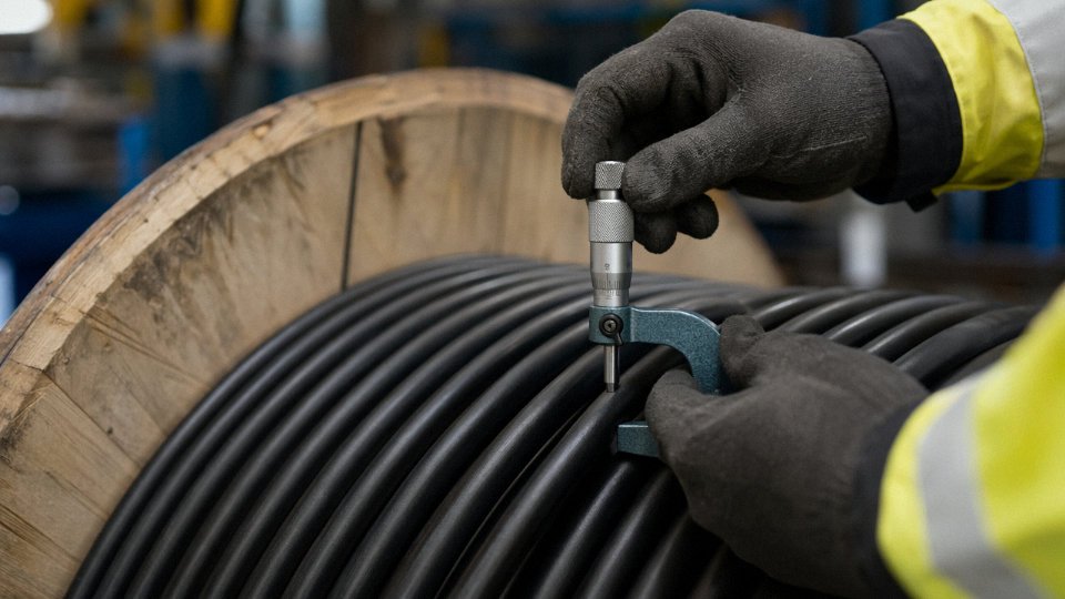
- Sheath thickness: cut a small section at the drum end and measure with a calibrated micrometer at four points around the circumference — IEC tolerances are tighter than most buyers assume, and a sheath 0.2–0.3 mm undersized on every drum is a pattern, not a fluke
- Conductor DC resistance: a Wheatstone bridge or decent digital micro-ohmmeter will tell you within minutes whether the actual conductor cross-section is close to declared — compare against the IEC 60228 maximum resistance values for the temperature at measurement
- Core color coding: verify it matches the standard specified (IEC, BS, or regional variant) — wrong color sequencing on a 3-core cable causes installation errors that are entirely avoidable
What a Factory Audit Should Actually Look For
A certificate on a wall doesn’t tell you much. If you’re auditing in person or sending a third party, the meaningful indicators are operational: Is there an in-line spark tester on every extrusion line? Is there a conductor resistance test bench that gets used on production output, not just periodically for show? Can the quality manager pull up test records by drum serial number in under five minutes? Are raw material compound certificates filed per batch and physically tied to production records?
Red flags worth walking away from: raw material drums staged near extrusion lines with no compound certificates attached, a single shared spark tester across multiple lines running at different voltages, and — frankly common in smaller operations — resistance test equipment that hasn’t been calibrated in over a year.
Pre-Shipment Inspection for High-Value Orders
For procurement above roughly 500 km of cable or $500,000 USD in contract value, major EPC contractors and utility buyers routinely require third-party pre-shipment inspection (PSI) by SGS, Bureau Veritas, Intertek, or an equivalent accredited body at the manufacturing facility before the order ships. PSI typically covers dimensional checks, conductor resistance verification on a statistical sample of drums, review of routine test records, and confirmation that drum serial numbers match the documentation package. It adds cost — usually 0.3–0.8% of contract value depending on scope and location — but it’s cheap insurance against a full-scale site failure.
Jinda’s manufacturing setup is built around exactly this level of scrutiny. Copper rod drawing through final drum testing happens within the same integrated production system, which means drum-level traceability isn’t a documentation exercise — it’s built into the production flow. The in-house laboratory runs IEC 60502 routine tests as a standard part of production, not as a separate QC event. Factory audits and third-party PSI are accommodated routinely, because in international tenders, cable quality is increasingly a contractual pass/fail requirement, not just a preference.