Specify the wrong cable for a new production line and you won’t find out immediately — you’ll find out six months later when the insulation softens under sustained load, a breaker trips during peak shift, and your maintenance crew spends a weekend tracing a fault that was baked in from day one. That kind of avoidable downtime routinely costs more than the entire cable procurement budget for the job. Getting the right cable type starts with understanding what your actual options are and what each one is genuinely built for.
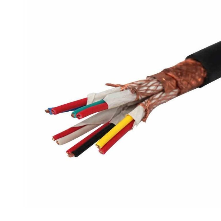
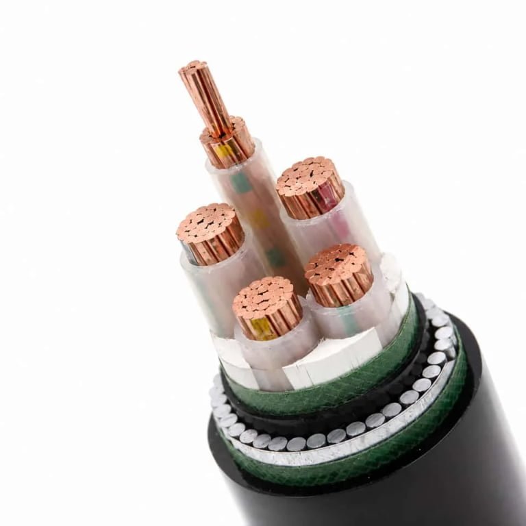
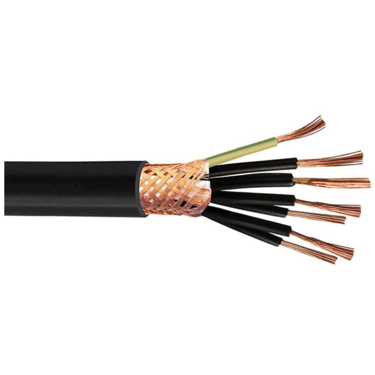
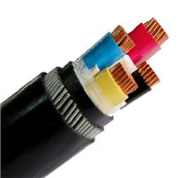
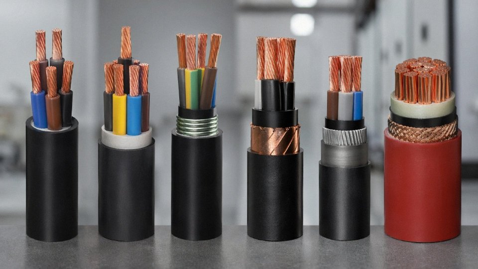
A power cable is an insulated electrical conductor — or assembly of conductors — designed to transmit electrical energy from a source to a load. Common examples include low-voltage XLPE cables rated 0.6/1 kV for building and industrial wiring, medium-voltage armored cables from 6 kV to 35 kV for grid distribution, rubber-sheathed flexible cables for mobile equipment, and fire-resistant or mineral-insulated cables where safety circuits must survive a fire.
What makes this genuinely complicated is that “power cable” isn’t a single product — it’s a loose category covering dozens of constructions that differ in conductor material, insulation chemistry, armor type, voltage class, and installation environment. A cable that performs flawlessly in a dry cable tray inside a factory will fail within a season buried in waterlogged soil. The examples worth examining aren’t just catalogue entries; each one reflects a specific engineering trade-off that has real consequences on the plant floor.
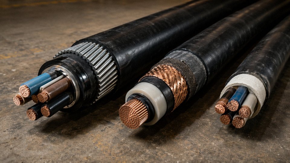
Seven Concrete Examples of Power Cables Used Across Voltage Classes and Industries
Power cables span an enormous range of constructions, voltage ratings, and environmental demands. The seven examples below cover the most common types you’ll encounter in real projects — from a subdivision trench to a submarine transmission corridor.
NYY / VV Low-Voltage Underground Cable (0.6/1 kV)
This is the workhorse of building services and residential infrastructure. PVC-insulated, PVC-sheathed, available in copper or aluminum conductors from 1.5 mm² up to 300 mm² — though in practice most building feeds run between 16 mm² and 150 mm², with the larger cross-sections reserved for main LV feeders from substations. Typical direct-buried installation sits at 0.7 m depth, sometimes shallower under concrete slabs where local codes allow. Where future access matters — road crossings, densely serviced trenches — contractors pull the cable through HDPE ducts instead. Direct-buried saves material cost upfront; duct installation saves excavation cost over the cable’s 30–40 year life. Get that trade-off wrong and you’re cutting a road open in year eight.
XLPE MV Distribution Cable (6/10 kV to 26/35 kV)
XLPE displaced paper-oil insulation as the dominant medium-voltage construction through the 1990s for good reason: it tolerates continuous conductor temperatures up to 90°C, handles short-circuit peaks to 250°C without catastrophic damage, and doesn’t leak. Copper wire screen provides fault current return path and field grading; the PE outer sheath handles soil chemistry. EPR is sometimes specified instead of XLPE where the cable runs through areas with frequent thermal cycling or where flexibility during installation matters — EPR stays pliable at lower temperatures and shows marginally better moisture resistance long-term, though it costs 15–25% more depending on compound prices that quarter.
Armored SWA Cable (Steel Wire Armored, 0.6/1 kV)
Galvanized steel wire armor between the inner bedding and outer PVC sheath gives this cable mechanical protection that NYY simply can’t match in quarries, outdoor industrial plants, and direct-buried runs under vehicle traffic. Multicore SWA designs use steel wire without issue. Single-core SWA is trickier — steel armor forms a shorted turn around a single AC conductor, generating eddy-current losses and heating. Single-core designs rated above roughly 50 mm² typically substitute aluminum wire armor instead. Missing that distinction in a spec leads to derating headaches or, worse, premature sheath failure.
Flexible Rubber-Sheathed Mining Cable (1.9/3.3 kV to 3.8/6.6 kV)
Continuous miners and longwall shearers drag their trailing cables through conditions that would destroy a standard cable in weeks. EPR insulation with CSP or EPR sheath construction gives the flex life needed — typically rated for several million flex cycles depending on bend radius and cable diameter. IEC 62233 and AS 1746 both mandate flame-retardant and anti-static properties; the anti-static requirement exists because a static discharge near methane or coal dust is not a theoretical risk.
Fire-Resistant and LSZH Cable (0.6/1 kV)
In tunnels, airport terminals, hospitals, and high-rise stairwells, the cable itself becomes a life-safety component. Mica tape wrapping around each conductor core maintains circuit integrity under direct flame exposure — IEC 60331 requires the cable to function for 90 minutes at 750°C or 830°C depending on the class. The LSZH outer compound addresses what kills people in enclosed fires: smoke density and halogen gas emission. IEC 60754-1 limits hydrogen chloride evolution to under 0.5% by weight. Specifying standard PVC in these locations isn’t just a code violation; it’s a documented cause of evacuation circuit failure.
LSZH cables emit significantly less toxic gas than standard PVC cables under fire conditionsTrue
IEC 60754 testing confirms LSZH compounds produce halogen acid gas well below the 0.5% threshold that PVC cables routinely exceed, with PVC releasing HCl at roughly 28–30% by weight of the compound.
High-Voltage XLPE Transmission Cable (66 kV to 500 kV)
At transmission voltage, cable construction becomes a precision engineering exercise. Extruded XLPE insulation with semi-conducting screens on both conductor and insulation surfaces controls field distribution; any void or contamination at those interfaces is a partial discharge site and an eventual failure point. The metallic sheath — lead or corrugated aluminum — provides both a moisture barrier and a fault return path. Current ratings on a 400 kV single-core cable in flat formation, adequately cooled, typically fall between 1,000 A and 1,400 A depending on soil thermal resistivity, burial depth, and whether forced cooling is installed. IEC 62067 governs the full type-test and pre-qualification program, which runs 12–18 months on its own. Budget that timeline into any project schedule.
Photovoltaic DC Power Cable (1.5 kV DC)
Solar farms generate DC at string voltages now commonly reaching 1,500 V, which standard LV AC cables are not rated to handle safely. PV-specific cables use tinned copper conductors with XLPE or EPR insulation compounded for UV resistance and ozone resistance, since string cables on a utility-scale farm spend 25+ years in direct sunlight. TÜV certification to 2 PfG 2279 is the European benchmark; UL 4703 is required for North American projects. Using uncertified cable on an export project creates insurance liability and often triggers re-inspection requirements that cost more than the cable savings ever could.
How Conductor Material and Cross-Section Determine Real-World Current Capacity
Conductor sizing is where procurement decisions get expensive fast. Undersize and you get thermal trips, accelerated insulation aging, or — worst case — a fire. Oversize and you’ve locked capital into copper or aluminum that’s sitting idle inside a conduit. Getting this right before you request a quote is not optional.
Ampacity Fundamentals and the IEC 60287 Baseline
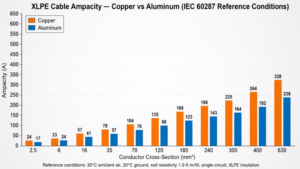
The table below reflects IEC 60287 methodology at standard reference conditions: ambient air 30°C, ground temperature 20°C, soil thermal resistivity 1.0 K·m/W, XLPE insulation, single-circuit installation. These are the numbers most manufacturers quote. Your site will almost certainly deviate from at least one of them.
| Conductor Cross-Section | Copper Ampacity (A) | Aluminum Ampacity (A) |
|---|---|---|
| 2.5 mm² | ~27 | ~21 |
| 6 mm² | ~46 | ~36 |
| 16 mm² | ~80 | ~63 |
| 35 mm² | ~120 | ~94 |
| 70 mm² | ~170 | ~133 |
| 120 mm² | ~220 | ~172 |
| 185 mm² | ~280 | ~220 |
| 240 mm² | ~330 | ~258 |
| 300 mm² | ~375 | ~295 |
| 400 mm² | ~440 | ~346 |
| 630 mm² | ~590 | ~465 |
Aluminum carries roughly 60% of the current a same-sized copper conductor can handle — that ratio comes directly from the conductivity difference, around 35 MS/m for aluminum versus 58 MS/m for copper. The practical consequence is that an aluminum cable one or two cross-section steps larger than its copper equivalent will usually match the thermal performance, though the exact step depends on where you land on the standard size ladder.
Derating: Where the Nameplate Numbers Stop Applying
Grouping cables changes everything. A single 185 mm² copper cable buried at 0.8 m might carry 280 A comfortably, but group three circuits in flat formation at 0.2 m spacing and that figure drops to somewhere in the 210–230 A range depending on mutual heating. Trefoil formation is somewhat better thermally than flat, but in practice many contractors default to flat simply because it’s easier to lay — and then forget to derate.
Soil thermal resistivity is the variable most engineers underestimate. Dry desert soil can hit 2.5–3.0 K·m/W; waterlogged clay may sit at 0.7 K·m/W or below. The difference in ampacity between those two extremes for a 240 mm² aluminum cable can be 15–25% — which on a long rural feeder is the difference between meeting load growth targets in year five or pulling a parallel cable.
Cyclic loading helps, usually. If your feeder serves a load that peaks 8–10 hours per day and drops significantly overnight, you may be able to apply a cyclic rating factor of 1.1–1.2 over the steady-state value, per IEC 60853. Whether your utility or EPC contractor will accept that in the design is another matter.
Worked Example: 400 A Rural Feeder
Say you have a 400 A three-phase feeder, direct buried at 1.0 m, soil resistivity measured at 1.2 K·m/W, ambient ground temperature 25°C, single circuit. Applying the relevant derating factors — roughly 0.94 for soil resistivity and 0.97 for ground temperature — your effective required ampacity works out to about 438 A. A 185 mm² copper XLPE cable rated 280 A baseline won’t cut it after derating. Step up to 240 mm² copper (baseline ~330 A, derated ~300 A) and you’re still short. The right answer here lands at 300 mm² copper or 400 mm² aluminum, with the aluminum option typically coming in 25–40% cheaper on material cost and roughly half the weight per meter — meaningful on a 10 km route when you’re calculating pulling tension and joint bay spacing.
The Copper-Versus-Aluminum Decision in Long Rural Runs
On a 10 km medium-voltage distribution project, aluminum conductors typically reduce cable purchase cost by 25–40% and cut overall cable weight by roughly 50% compared with copper equivalents. For a procurement manager, that weight reduction matters beyond price: fewer drum changes, lighter pulling equipment, lower civil cost per joint bay.
Aluminum conductors in direct-buried MV cables require bimetallic connectors and proper compression jointing to prevent galvanic corrosion at copper-aluminum interfaces.True
Electrochemical potential difference between copper (approximately +0.34 V) and aluminum (approximately -1.66 V) drives accelerated corrosion at direct metal-to-metal contact, especially in the presence of moisture. IEC and industry standards require bimetallic transition connectors or bi-metal lug terminations at all copper-aluminum junctions.
The jointing cost and skill requirement for aluminum is real — don’t let a contractor quote aluminum cable and then use copper-only lugs to save twenty minutes per termination. That’s how you get a joint failure at year three.
Jinda’s production range spans 1.5 mm² through 2,500 mm² in both copper and aluminum conductors, covering everything from final subcircuit wiring at the DB board up to main HV feeders entering a substation. For a project with a complex bill of materials — say, a solar farm with string cables, collector cables, and a 35 kV export feeder all on one purchase order — single-source procurement from one manufacturer simplifies conformity documentation, cuts logistics coordination, and gives you one throat to grab if there’s a quality issue.
Insulation and Sheathing Materials: Matching Cable Chemistry to Operating Environment
Picking the wrong insulation system doesn’t just shorten cable life — it can trigger a Class A fire in a cable tray, contaminate a food-grade production line, or leave a maintenance crew pulling frozen, cracked cable out of an Arctic conduit at -40°C. The conductor handles current; the insulation and sheath handle everything the environment throws at it. Those are very different engineering problems.
PVC: The Workhorse With Real Limits
PVC remains the default for indoor low-voltage wiring and lightly buried general-purpose runs, and honestly, for a lot of applications it’s still the right call. It’s cheap, widely available in every cross-section you’ll need, and adequately rated for continuous conductor temperatures up to 70°C. Installation crews know it. Termination hardware is universal.
The problems show up when the environment pushes back. In a fire, PVC sheaths can emit somewhere around 28% HCl by mass — corrosive enough to destroy switchgear in adjacent panels well after the fire itself is suppressed. Below roughly -15°C, the plasticizers stiffen and the sheath cracks under bending; anyone who has tried to pull standard PVC cable through a conduit on a January morning in northern Europe or northern China knows exactly what this looks like. Near oil, hydraulic fluid, or industrial solvents, plasticizer migration softens the sheath over months and causes surface tackiness and dimensional change. For a dry plant room or an office building in a temperate climate, PVC is fine. For a chemical plant, an offshore platform, or a tunnel evacuation circuit, it isn’t.
XLPE: The Thermal and Electrical Performance Standard
Cross-linked polyethylene became the dominant insulation for power cables above roughly 1 kV during the 1990s, and the reason is straightforward: the thermosetting cross-linked structure holds its geometry at 90°C continuous and 250°C under short-circuit conditions, without the softening or flow that limits standard thermoplastic insulation. At medium and high voltage, lower dielectric losses also matter — XLPE’s tan delta sits in the range of 2–4 × 10⁻⁴, versus 60–100 × 10⁻⁴ for PVC, which is why XLPE is effectively mandatory above 11 kV on any serious distribution network.
The crosslinking process itself affects long-term performance in ways that procurement specs often don’t capture. Peroxide crosslinking, the dominant industrial method, produces a uniform network with good tan delta stability but requires careful degassing to remove byproduct volatiles — incomplete degassing causes treeing in medium-voltage service. Silane moisture-cure crosslinking is cheaper and suitable for lower-voltage cables but produces somewhat less consistent network density and ages faster under cyclic thermal loading. Electron-beam crosslinking offers tight dimensional control and no chemical byproducts, used mainly for thin-wall specialty cables rather than large-conductor MV distribution cables. If you’re specifying cables for a 33 kV substation feeder with a 30-year design life, asking your supplier which crosslinking process they use is not an unreasonable question.
EPR: Cold Environments and Moving Applications
Ethylene propylene rubber insulation occupies a specific niche that XLPE doesn’t fill well: applications requiring repeated flexing, extreme cold, or persistent ozone and UV exposure. EPR remains flexible and ductile down to around -50°C, which matters enormously for mining trailing cables, offshore drill platform power feeds, shipboard cables, and railway traction applications where the cable moves with the train or the dragline bucket. Ozone resistance is excellent — relevant anywhere near high-voltage corona discharge or UV-heavy outdoor environments.
One practical note for engineers comparing EPR against XLPE at the same voltage rating: EPR typically requires slightly greater insulation wall thickness to achieve equivalent electrical performance, so a direct substitution in a conduit sized for XLPE may need a conduit fill recheck.
LSZH and LSOH: When Smoke Kills Before Flame Does
In confined evacuation environments — metro tunnels, cross-channel rail tunnels, data centers, naval vessels, offshore platform accommodation modules — the fire performance of standard PVC sheathing is simply unacceptable. A burning PVC cable produces dense, near-opaque black smoke and corrosive HCl gas; measured optical transmittance under IEC 61034 conditions is effectively zero, and the HCl concentration can incapacitate people within minutes of ignition.
LSZH (low smoke zero halogen) and LSOH compounds are specified precisely to address this. Under IEC 61034, compliant LSZH cables maintain optical transmittance above 60%, and HCl emission stays below 0.5% by mass. The tradeoff is real: LSZH compounds are harder, less flexible than PVC, and more expensive — typically 15–40% cost premium depending on cross-section and order volume. They also require slightly more careful installation in cold conditions. But in any project where the cable standard references IEC 60332-3 or where the facility is designed around life-safety evacuation, this is a non-negotiable specification, not a value-engineering target.
Mineral Insulation (MICC): When the Cable Must Survive the Fire
Mineral-insulated copper-clad cable — magnesium oxide packed around solid copper conductors inside a seamless copper tube — operates continuously at up to 250°C and can survive fire exposure approaching 1,000°C, which is why fire pump circuits, emergency lighting feeders, and smoke control system power supplies are routinely specified in MICC regardless of cost. Nothing else reliably maintains circuit integrity in a fully developed structural fire.
Installation limitations are significant and sometimes underestimated. The magnesium oxide fill is hygroscopic; cut ends must be sealed with approved termination pots immediately, and any delay in a humid environment will absorb moisture and degrade insulation resistance to unusable levels — a mistake that results in pulling and reterminating the entire run. Bending radius is constrained; MICC cable cannot be routed through tight corners the way XLPE can. Labor installation cost is higher, typically 2–4× that of equivalent XLPE cable on a per-meter basis depending on termination count and routing complexity.
Selection Matrix: Environment to Material System
| Operating Environment | Recommended Insulation | Recommended Outer Sheath | Voltage Range Typical | Key Driving Factor |
|---|---|---|---|---|
| Indoor dry (office, residential) | PVC | PVC | 0.6/1 kV | Cost, availability |
| Outdoor UV exposure | XLPE or HDPE-sheathed | UV-stabilized PE or CSP | 0.6/1 kV–33 kV | UV degradation of standard PVC/XLPE |
| Direct buried, moist soil | XLPE | PE with steel wire armor | 0.6/1 kV–35 kV | Moisture ingress, mechanical damage |
| Submerged / underwater | XLPE | Lead sheath or double PE | 11 kV–220 kV | Radial water barrier |
| High fire risk / confined space | LSZH | LSZH | 0.6/1 kV | Smoke toxicity, IEC 60332 compliance |
| Fire survival circuit | Mineral (MICC) | Bare copper or LSF oversheath | 0.6/1 kV | Circuit integrity under fire |
| Chemical plant / oil exposure | EPR or XLPE | CSP or PUR | 0.6/1 kV–11 kV | Oil/solvent resistance |
| Arctic / extreme cold (-40°C+) | EPR | CSP or cold-flex PVC | 0.6/1 kV–6 kV | Low-temperature flexibility |
| Mining / trailing flex cable | EPR | Heavy-duty neoprene | 3.3 kV–11 kV | Repeated flexing, mechanical abuse |
| Shipboard / offshore | EPR or XLPE | LSZH or mud-resistant CSP | 0.6/1 kV–11 kV | Flame spread, salt, movement |
LSZH cables emit less than 0.5% HCl by mass under IEC 60754 test conditions, compared to approximately 28% HCl emission from standard PVC compoundsTrue
These figures are consistent with published IEC 60754-1 and IEC 60754-2 test data and are widely cited in cable fire performance standards and manufacturer technical documentation.
The right material system is almost never the cheapest option in isolation — but it’s usually the cheapest option once you account for what happens when it fails.
Armoring, Shielding, and Screening: When and Why These Structural Layers Are Specified
These two categories of cable protection get conflated constantly in tender documents, and the confusion costs real money — either through under-specified cables that fail in service or over-specified designs that add unnecessary material cost to every meter of a long run.
Armor is mechanical. Screening is electrical. They solve different problems, and a cable can have one without the other, both, or neither, depending entirely on the installation environment and system earthing arrangement.
Steel Wire Armor vs. Steel Tape Armor — Not Interchangeable
SWA (steel wire armor) is the right call when a cable faces tensile stress: pulling through a steep conduit, dropping down a vertical shaft, or running along a catenary. A multicore SWA cable in the 95–240 mm² range will typically sustain somewhere between 20 and 60 kN of pulling tension — the actual figure depends on the armor wire diameter, the number of wires, and the overall cable OD. For a 150 mm² four-core 0.6/1 kV SWA cable, expect roughly 25–35 kN. Push beyond that without a proper pulling sock and you risk deforming the bedding layer under the armor, which can crack XLPE insulation you won’t see until the cable’s already energized.
STA (steel tape armor) does something different. It resists radial crushing — the kind of load you get in compacted backfill, under a road where settlement keeps shifting, or anywhere a cable might get pinched rather than pulled. The interlocked tapes handle that radial squeeze well. They handle almost no tensile load. Specifying STA on a vertical cable run is a specification error, full stop.
The AWA Question on Single-Core Cables Above 11 kV
This one comes up regularly on HV projects, and it’s worth explaining carefully because the physics is counterintuitive to engineers who don’t work with HV cables daily.
Wrap steel armor — a ferromagnetic, electrically continuous tube — around a single-core AC cable, and you’ve created a closed magnetic circuit around an AC conductor. That induces circulating currents in the armor, which turn into resistive losses. Depending on loading level and armor continuity, this can increase total cable losses by somewhere in the 10–30% range. On a lightly loaded cable, it’s irritating. On a heavily loaded feeder running near rated current, it’s a continuous thermal penalty that shortens insulation life and inflates operating cost over a 30–40 year asset life.
AWA (aluminum wire armor) breaks that magnetic loop. Aluminum is non-ferromagnetic, so the circulating current effect is negligible. The mechanical protection function is essentially preserved. Specifying steel wire armor on a single-core 33 kV cable because “it’s stronger” is a mistake that looks fine on paper and costs money every hour the cable is energized.
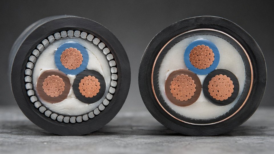
Steel wire armor on single-core AC cables above 11 kV increases losses by 10–30% due to induced circulating currents in the ferromagnetic armor.True
Confirmed by IEC 60287-1-1 eddy current and circulating current loss calculation methodology; the loss magnitude depends on bonding arrangement, conductor current, and armor resistance — typically quoted at 10–30% additional loss in engineering literature and cable manufacturer technical guides.
Copper Wire Screens and Tape Screens — Sizing Matters
A copper screen on an MV or HV cable does three things: it contains the electric field within the insulation (preventing field fringing into the bedding and armor), provides a low-impedance return path for earth fault current, and offers a degree of EMI shielding.
Screen cross-section sizing is governed by earth fault current magnitude and the fault clearance time of your protection relay. IEC 60502-2 Annex B lays out the calculation — basically a thermal withstand check. A 16 mm² copper wire screen might handle a 5 kA fault cleared in 0.5 seconds on an 11 kV feeder. Specify that same cable on a busbar-fed feeder where fault level reaches 12 kA and you’ll melt the screen before the relay trips. The screen cross-section has to match your actual system fault level, not just a generic project standard.
Putting It Together: Two Practical Scenarios
For a direct-buried 11 kV feeder in an active construction zone — excavators overhead, possible rodent activity, backfilled trench — the right specification is a copper wire screened, SWA, XLPE/PVC cable. The SWA handles the mechanical threat. The copper wire screen handles fault current return and field containment. Relatively straightforward.
A single-core 33 kV cable in a cable tunnel is a different problem. No crushing load, no rodent risk, but moisture ingress into XLPE insulation over a 30-year service life is a real degradation mechanism, especially in a tunnel with humidity cycling. Here you want AWA (not SWA, for the reasons above), copper wire screen sized to fault level, and a lead alloy sheath between the insulation screen and the armor to act as a moisture barrier. The lead sheath adds cost and weight. On a 33 kV asset with a multi-decade design life, it’s usually justified. On a 5-year temporary supply cable, probably not.
Understanding what each layer actually does — and what it doesn’t do — is what separates a competent cable specification from one that just copies last project’s bill of materials.
Reading and Writing a Complete Cable Specification: Decoding Type Codes and Standards
A cable code looks like noise until you know the grammar. Once you do, a string like ZR-YJV22-8.7/15kV-3×185mm² tells you almost everything about the construction in under thirty characters — and any discrepancy between that code and what arrives on your drum is a site rejection waiting to happen.
Decoding a Real Designation Character by Character
Take ZR-YJV22-8.7/15kV-3×185mm² and strip it apart left to right:
| Code element | What it means | Construction feature it locks in |
|---|---|---|
| ZR | Flame retardant | Bundle flame test per IEC 60332-3 |
| YJ | XLPE insulation | 90°C continuous, 250°C short-circuit |
| V | PVC inner sheath | Mechanical protection over cores |
| 22 | Double steel tape armor + PVC outer sheath | Longitudinal crush resistance, buried or duct runs |
| 8.7/15 kV | Voltage class (U₀/U) | Conductor-to-earth / conductor-to-conductor |
| 3 | Three cores | Three-phase circuit |
| 185 mm² | Conductor cross-section | Ampacity and voltage drop basis |
Every letter is a testable commitment. “YJ” means the insulation must pass IEC 60502-2 type tests for XLPE, not generic thermoplastic. “22” means double steel tape, not SWA — if a supplier substitutes single wire armor to cut costs, the code doesn’t match and the tender is non-compliant. In practice, I’ve seen procurement teams accept a substitution on armor type because nobody decoded the suffix. That cable later failed a site pull-in test because the laying tension rating was wrong.
The U₀/U Voltage Convention — and Why Your System Earthing Arrangement Changes the Answer
The slash in 8.7/15 kV is not decorative. U₀ is the rated voltage between any conductor and earth (or the metallic screen). U is the rated voltage between any two phase conductors. For a 15 kV line-to-line system that is solidly or effectively earthed, 8.7/15 kV is correct. On an isolated or high-impedance earthed network running at the same line voltage, a ground fault leaves the unfaulted phases at full line-to-line voltage against earth — you need the next voltage tier up, typically 12.7/22 kV, for the same 15 kV network. Get this wrong and you’re running the insulation at a sustained overstress it was never tested for.
The same logic applies at low voltage. A 0.6/1 kV cable is not a “1 kV cable.” A TN-S system at 400 V line-to-line gives 230 V conductor-to-earth, comfortably within 0.6 kV. Mistakenly ordering a 1.8/3 kV construction for a 1 kV industrial system wastes money and creates a wall-thickness mismatch with termination hardware. Ordering 450/750 V rated cable where 0.6/1 kV is required is the more dangerous error, and it happens more than it should on fast-moving retrofit projects.
The Minimum Data Fields a Purchase Order Must Contain
A technically complete cable order — one that cannot be misinterpreted by a manufacturer in a different country working from a different default standard — needs at minimum:
- Voltage class in U₀/U format
- Conductor material (copper or aluminum) and cross-section in mm²
- Number of cores and whether a reduced neutral or earth core is included
- Insulation type (XLPE, PVC, EPR, LSZH, MI)
- Armor type and sheath type
- Applicable standard: IEC 60502, BS 5467, AS/NZS 1429, NFC 32-321, UL listed — pick one and state it explicitly
- Drum length and tolerance (±3% is typical, but renewable energy projects sometimes need ±1% to avoid mid-run joints)
- Special properties: ZR/flame retardant, FR/fire resistant, LSZH, UV stabilized, cold-bend rated
- Third-party certification requirement if needed (KEMA, SGS, DNV, etc.)
Omit the voltage class suffix on a medium-voltage order and you may receive a general-purpose unscreened construction. Omit the standard reference and the factory defaults to whatever national code it knows best. Neither outcome is recoverable without costly remakes or quarantine holds.
Specification Errors That Cause Delays and Rejections
Copper armor on a single-core HV cable is a textbook error — eddy currents induced in a closed magnetic loop around a single-phase conductor will overheat the armor under load and create a parasitic loss that shows up as unexplained energy consumption or insulation degradation within 18–24 months. Single-core HV cables need non-magnetic armor (aluminum wire, or no armor where the installation design allows).
Specifying ZR (flame retardant) when the project calls for FR (fire resistant, circuit integrity maintained under flame) is a different failure mode entirely. ZR cable stops flame spread; FR cable keeps the circuit alive in a fire. Confuse them on a fire-pump circuit and you’ve passed a procurement audit while failing a life-safety requirement.
IEC 60502-2 requires XLPE-insulated medium-voltage cables to pass a conductor temperature of 250°C during short-circuit type testing.True
IEC 60502-2 specifies the short-circuit conductor temperature limit for XLPE insulation at 250°C, consistent with the thermal properties of cross-linked polyethylene and aligned with IEC 60228 conductor requirements.
How a Pre-Sales Technical Review Catches These Problems Before Production
Jinda’s pre-sales engineering team treats an incoming specification as a document to audit, not just a production instruction. Ambiguities — an unspecified earthing arrangement, a missing armor type, a voltage class that doesn’t match the stated system voltage — are flagged in writing before any production order is confirmed. The team issues a Technical Data Sheet aligned with IEC 60502 and IEC 60228, specifying actual construction dimensions, conductor resistance, insulation thickness, and test voltages, so the project engineer can verify alignment with the design before a meter of cable is extruded. Third-party test reports from recognized bodies can be coordinated at the inquiry stage, not chased after the drums are on a ship. That sequence matters: a test report issued post-shipment that reveals a marginal result gives you no leverage and no time.
Installation Methods That Directly Affect Cable Selection and Long-Term Performance
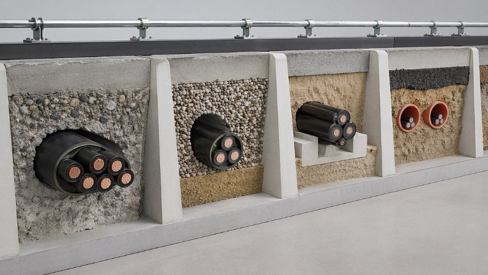
Cable type and installation method are inseparable. You cannot finalize a cable construction until you know exactly how it will be laid — and in practice, plenty of project problems trace back to someone specifying a cable in isolation, handing it to a contractor, and discovering the construction is wrong for the trench, the duct bank, or the riser shaft on the day of installation.
Direct Burial in Soil
Direct burial is where thermal resistivity bites hardest. Soil is not a uniform medium — arid, sandy backfill can reach a thermal resistivity of around 2.5 K·m/W, roughly three times worse than moist clay at 0.85 K·m/W. That difference forces a real ampacity penalty: for a 95 mm² copper XLPE cable, you may find that the sandy-soil site requires stepping up to 120 mm² just to carry the same sustained load. Contractors sometimes push back on the upsizing cost, but the alternative is accelerated insulation aging and a premature cable failure that costs far more to excavate and repair.
Mechanically, direct-buried cables need either steel wire or steel tape armor plus a UV-stable polyethylene outer sheath. Warning tape at 300–400 mm above the cable is a code requirement in many jurisdictions, not optional. Burial depth varies by local standard — typically 600–900 mm for LV, 900–1,200 mm for MV — and frost depth matters in northern climates.
Cable Duct and Conduit
Running cable through HDPE or PVC duct allows unarmored construction, since the duct itself provides mechanical protection. The limiting factor shifts to pulling tension. For a 185 mm² three-core XLPE cable, sidewall pressure at a 90° bend should not exceed roughly 3,000 N/m; exceed that and you risk deforming the insulation or crushing the conductor at the bend. Calculate pulling tension using a friction coefficient of around 0.35 for HDPE duct — that number climbs noticeably if the duct has been in the ground a few years and has joint misalignments, so build in margin.
Lubricant selection matters too. Water-based cable-pulling lubricant is compatible with XLPE and PVC sheaths; petroleum-based products can swell PVC over time, which is the kind of slow-motion problem nobody notices until a scheduled outage pulls a cable and finds it bonded to the duct wall.
Cable Tray and Ladder Rack
Open-air tray and ladder rack installation is common in industrial plants and substations. A single cable on an open tray runs at full rated current. Bundle six cables in a touching trefoil group on the same tray and you’re looking at a derating factor in the vicinity of 0.72 — that’s a meaningful reduction, and on heavily loaded trays in a process plant, it adds up fast.
Flame-retardant construction per IEC 60332-3 is essentially mandatory for densely populated cable trays. Untreated PVC may technically pass IEC 60332-1 as an individual cable but will propagate fire along a fully loaded tray. The distinction matters at the specification stage, not after the fact.
Vertical Risers and Shafts
Vertical runs introduce a mechanical load that horizontal installations never see. A 185 mm² three-core SWA cable runs roughly 7–9 kg per meter depending on conductor material and sheath thickness — so a 30 m vertical riser imposes 210–270 kg of sustained tension at the top cleat. Specify cables with a defined tensile strength rating for vertical service, and cleat at no more than 1 m intervals using spring-loaded cleats that accommodate thermal expansion. Rigid cleats on a cable that cycles thermally will eventually crack the outer sheath at each cleat edge.
Spring-loaded cleats are required for vertical cable runs to prevent sheath cracking from thermal cycling.True
Rigid cleats create stress concentration points on the cable sheath as the cable expands and contracts with load cycling. Spring-loaded or cushioned cleats distribute that movement and are widely specified in IEC and BS installation standards for vertical runs.
Submarine and Underwater
Submarine cable construction is in a different league from land cable. Longitudinal water-blocking — either tape or gel-filled conductor interstices — is non-negotiable; a single breach in the outer sheath without longitudinal blocking allows water to track the full cable length. A lead or corrugated aluminum moisture barrier sits beneath the armor. Double SWA is standard for seabed installations subject to abrasion and anchor drag.
One practical constraint that often surprises procurement teams: standard cable lay barges operate tensioning equipment sized for cables up to roughly 150 mm outside diameter. Specify a heavier cable without checking the installation vessel’s capability and you may be looking at a specialized vessel at significantly higher day rates.
Tying It Back to Construction Type
These installation demands explain why the flexible mining cable from the earlier examples is built the way it is. A continuous miner cable coils and uncoils on a cable reel hundreds of times per shift. That repeated flexing would fatigue-crack the conductors of a standard rigid SWA cable within weeks — the fine-wire stranded conductors and elastomeric sheath of a mining flexible cable are specifically engineered for that mechanical duty cycle, not merely for the electrical rating. The voltage rating might be identical to a fixed-installation cable; the construction is entirely different, and substituting one for the other is a maintenance failure waiting to happen.
| Installation Method | Armor Required? | Key Limiting Factor | Typical Derating vs. Single Cable |
|---|---|---|---|
| Direct burial, sandy soil | Yes (SWA/STA) | Soil thermal resistivity | Up to –15% ampacity vs. moist clay |
| HDPE duct/conduit | No | Pulling tension, sidewall pressure | Depends on grouping in duct bank |
| Open cable tray, single | No | Flame-retardant spec | None (baseline) |
| Open cable tray, 6-cable group | No | Grouping derating | ~0.72 factor |
| Vertical riser, 30 m | Yes (for weight support) | Tensile load at cleat | None electrical, but mechanical rating governs |
| Submarine seabed | Yes (double SWA) | Water-blocking, vessel OD limit | Site-specific, burial depth dependent |
International Certifications and Test Reports: What to Request Before Accepting a Cable Shipment
Getting the specification right on paper means nothing if the drums arriving on site aren’t what you ordered. This is where the certification and test-report conversation becomes very practical — and where a lot of projects quietly absorb problems they don’t discover until commissioning, or worse, after a fault.
Type Tests, Routine Tests, and Sample Tests: Three Different Answers to Three Different Questions
These three categories get conflated constantly in purchase orders, and the confusion is expensive.
A type test, conducted under IEC 60502-1 Clause 18 (for LV) or IEC 60502-2 Clause 18 (for MV), proves that a specific cable design meets the standard. It’s run once — or again whenever the construction changes — and covers things like bending, partial discharge, and impulse withstand. When you request a type test report, you’re asking: “Does this cable design fundamentally work?” The report covers a design, not your drums.
Routine tests are performed on every manufactured drum before it leaves the factory. Conductor resistance per IEC 60228, AC high-voltage withstand (3.5 kV for five minutes on a 1 kV-rated cable is typical), insulation resistance, and a dimensional and visual check. These are the tests that actually protect you. A drum arriving on site without a factory test certificate attached to it — physically or digitally traceable to that drum’s serial number — should be refused. Full stop.
Sample tests sit between the two: statistical checks on a subset of production output, typically covering mechanical and dimensional properties. They’re often overlooked in procurement documents, but they catch batch drift that routine electrical tests won’t flag.
Request all three categories in your contract. Specify that the factory test certificate serial number must match the drum label before unloading. This one contractual clause has saved projects from accepting entire shipments of borderline cable.
Verifying the Factory Test Report: What the Numbers Actually Mean
When a test report arrives, the instinct is to glance at “PASS” and file it. Don’t.
Pull up IEC 60228 Table 1 and check the measured conductor resistance at 20°C against the maximum permitted value for that cross-section and conductor class. A 185 mm² Class 2 copper conductor carries a maximum resistance of 0.0991 Ω/km. If the reported value is, say, 0.0985 Ω/km, that’s fine — but if the report shows a suspiciously round number or a value right at the limit, ask for the raw measurement data. Also confirm the test temperature and that the resistance was corrected to 20°C; resistance measurements taken at 35°C ambient without correction will read lower than reality.
Insulation resistance index: the minimum acceptable figure is typically 0.01 MΩ·km, but well-made XLPE cable will run several orders of magnitude above that. A value that barely passes warrants a conversation with the manufacturer.
Check the test date. Cable has a shelf life, and XLPE in particular can absorb moisture during prolonged improper storage. If the factory test was conducted eighteen months before the drums hit your yard, ask about storage conditions.
Third-Party Certifications by Export Market
CE marking alone does not verify cable performance — it requires a Declaration of Conformity under the Construction Products Regulation (EU 305/2011) with a declared reaction-to-fire class.True
CE marking on cables in the EU is governed by the CPR, not the Low Voltage Directive. The CPR requires cables to be tested and classified for reaction to fire (e.g., Eca, Dca, Cca) under EN 50575, and a Declaration of Conformity must accompany the product. CE marking without CPR compliance is not valid for cables installed in construction works in EU member states.
The relevant certification depends entirely on the destination:
| Market | Certification / Scheme | What It Covers |
|---|---|---|
| EU (construction) | CPR DoC — Eca / Dca / Cca fire class | Reaction to fire under EN 50575 |
| UK | BASEC approval | Construction, performance, ongoing factory audits |
| Netherlands / Belgium | KEMA-KEUR | Grid connection, utility acceptance |
| Italy | CESI / IMQ | Utility and construction compliance |
| Australia / New Zealand | SAA / RCM (formerly C-Tick) | AS/NZS standards compliance |
Don’t assume a CPR-marked cable is acceptable for a Dutch utility project — KEMA-KEUR is a separate scheme with its own audit cycle. These aren’t interchangeable.
Jinda’s Quality Infrastructure
Jinda operates under an ISO 9001:2015 certified quality management system with full material traceability from the incoming copper rod or aluminum rod purchase lot through every production stage to the finished drum. Type tests are conducted at CNAS-accredited third-party laboratories with witness inspection available for major project orders, which matters when a client’s own engineer or a lender’s technical advisor needs to sign off on the qualification data. The in-house high-voltage test laboratory handles AC withstand testing up to 110 kV, covering the MV cable range without relying on external lab scheduling for routine production release. For export shipments, third-party pre-shipment inspection and drum-level documentation packages can be coordinated to match the acceptance protocols of specific destination markets — because the paperwork requirements in, say, an Australian infrastructure project look nothing like what a European utility requires.
Frequently Asked Questions About Power Cable Examples and Specifications
What is the most common example of a power cable used in homes?
The most widely installed residential power cable worldwide is a flat, 2-core or 3-core PVC-insulated, PVC-sheathed cable — designated NYM-J or similar under IEC 60227 — in 1.5 mm² for lighting circuits and 2.5 mm² for socket outlet circuits. Voltage rating is typically 300/500 V or 450/750 V depending on which national wiring rules apply. That said, specifics vary more than many buyers expect: the UK uses twin-and-earth flat cable to BS 6004, Australia uses TPS to AS/NZS 5000.2, and North American residential wiring follows NM-B (Romex-type) to UL 719. The construction differs, but the underlying job is the same — get power from a distribution board to a light fitting or socket without starting a fire. For procurement purposes, always confirm which national standard the end-market requires before placing a bulk order; “standard residential cable” is not a universal specification.
What is the difference between a power cable and a power cord?
Short answer: one stays put, one moves. A power cable is permanently installed in infrastructure, a building, or a plant — it lives inside conduit, buried in a trench, or clipped to a tray and is not intended to be disconnected repeatedly. A power cord (flexible cord, appliance cord) connects portable equipment to an outlet and flexes every time someone moves the kettle or the power tool. The governing standards are different: IEC 60502 and national equivalents cover fixed-wiring power cables; IEC 60227 and IEC 60245 cover flexible cords. Mixing them up in a specification is a real procurement error — a flexible cord is not rated for sustained current loading in a fixed installation, and using it that way is both a fire hazard and a code violation in most jurisdictions.
Can XLPE cables be used outdoors without additional protection?
It depends almost entirely on the outer sheath compound, not the XLPE insulation itself. XLPE cables with a UV-stabilized black HDPE or MDPE outer sheath are fine on exposed cable trays, poles, or aerial installations without further protection — the carbon-black loading in the sheath handles UV. But XLPE cables with a standard natural or colored PVC outer sheath need conduit or trunking outdoors. Ordinary PVC compounds degrade under prolonged UV and typically become brittle within roughly 3–5 years in hot, sunny climates; in my experience the failure shows up first as surface cracking that lets moisture in, not as an immediate flashover. Specify sheath compound explicitly when ordering cables for outdoor runs. Leaving it to the supplier’s default is a risk.
XLPE insulation itself is UV-resistant and requires no outer sheath protection for outdoor installations.False
XLPE insulation degrades under UV exposure. UV resistance in outdoor cables is provided by the outer sheath compound — specifically carbon-black-loaded HDPE or MDPE — not by the XLPE insulation layer. Cables with standard PVC outer sheaths require conduit or physical protection when installed outdoors.
How long does a correctly installed power cable last?
IEC 60502-2 sets a 30-year design life for medium-voltage XLPE cables at rated voltage and temperature. In practice, cables in well-installed, thermally managed systems routinely operate 40–50 years without intervention. The gap between design life and actual service life is usually explained by what happens during installation and operation, not by the cable material itself. Water treeing in unscreened MV cables, sustained overcurrent that quietly cooks insulation over months, and mechanical damage at joints and terminations account for the large majority of premature failures. A cable buried correctly in a properly dimensioned duct, with well-made terminations, barely gets stressed in normal service.
What is a 4-core versus 3-core power cable and when is each used?
A 3-core cable carries three phase conductors and suits balanced three-phase systems — delta-connected loads, balanced star loads — where neutral return current is essentially zero. Add unbalanced single-phase loads fed from a TN-S or TT distribution system and you need a 4-core cable with a dedicated neutral conductor. There is also the 3-core-plus-earth variant (3C+E), which adds a smaller-cross-section protective earth conductor for equipment grounding without carrying load current. Getting this wrong in a tender is surprisingly common: specifying 3-core where 4-core is needed forces a change order on site, which costs time and usually more money than the cable difference itself.
Are aluminum power cables safe for building wiring?
For conductors 16 mm² and above, yes — aluminum is the standard choice for service entrance cables, main distribution feeders, and inter-panel risers in commercial buildings across North America, Australia, and much of Asia. The economics make sense at larger cross-sections and the engineering is well understood. Below roughly 10 mm², aluminum becomes problematic in building wiring: higher resistivity means a physically larger conductor for the same ampacity, oxide layer formation at terminals increases contact resistance over time, and every termination must use aluminum-rated lugs and anti-oxidant compound. Omit those lugs and you get a warm connection that gets warmer — a well-documented failure mode. For branch circuits and small cross-sections, copper remains the practical default for residential and light commercial work.
What certifications should I request when importing power cables from China?
This question comes up constantly, and the honest answer is that the required certification set depends on the destination market — there is no single universal list. For EU projects, request a CPR Declaration of Performance, CE mark, and Euroclass fire rating. For UK projects, BASEC approval or LPCB certification. For Australian projects, RCM mark under AS/NZS standards. Across all export projects, regardless of destination, request IEC-compliant factory routine test reports, third-party type test reports from a CNAS- or ILAC-MRA-accredited laboratory, an ISO 9001 certificate, and material compliance documentation confirming RoHS and REACH compliance. The test reports matter as much as the certificates — a certificate without supporting test data from an accredited lab is not meaningful evidence of conformance. Build these requirements into your purchase contract, not just your incoming inspection checklist; it is far easier to enforce them before shipment than after a container arrives on site.