Specify the wrong cable type on a procurement order and you might not find out until installation day — when the electrician on-site tells you the jacket won’t survive the chemical exposure, or the insulation rating is marginal for the operating voltage, or the armoring is missing entirely. Rework at that stage is expensive. Delays ripple. In large infrastructure builds, a misspecified cable running through conduit that’s already been buried is a genuinely ugly problem to solve.
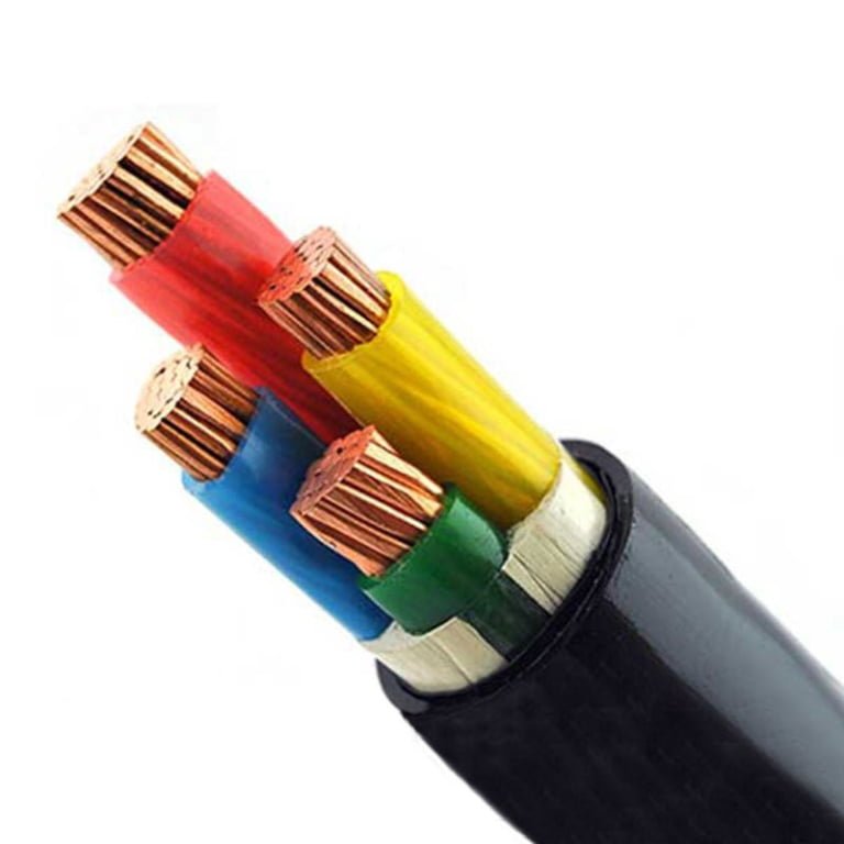
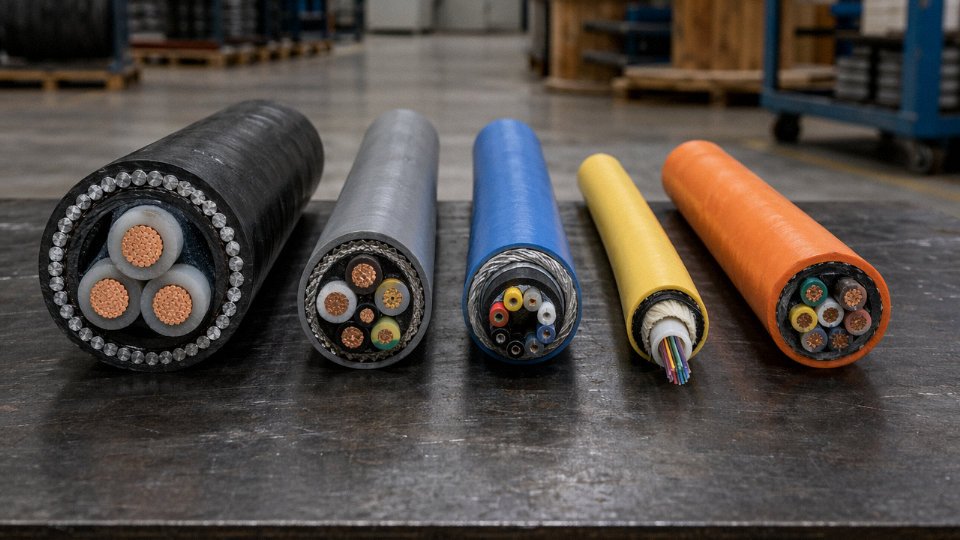
The five main types of cable are power cables, control cables, instrumentation cables, communication cables, and flexible/specialty cables. Each is engineered for a distinct combination of voltage class, signal type, mechanical environment, and regulatory requirement. Choosing correctly depends on matching those four variables to your actual installation conditions — not just picking the cheapest option in the right gauge.
What makes this more complicated than it sounds is that the five categories overlap in ways that trip up even experienced procurement managers. A low-voltage power cable and a control cable can look nearly identical off a reel, and both might carry 600 V — but run them in the wrong application and you’ll see problems in electromagnetic interference, thermal performance, or long-term insulation integrity that don’t show up until the plant has been running for a year. The global cable market sits somewhere around USD 225 billion annually, with low-voltage power cables alone accounting for roughly 40–45% of total consumption in construction and infrastructure. That scale means the industry has developed highly specific product families for good reasons. Understanding those reasons is how you avoid expensive substitutions.
Type 1 — Power Cables: Construction Layers, Voltage Classes, and Current Capacity Benchmarks
Power cables are the workhorse of the entire cable industry — by volume, low-voltage power cables alone account for an estimated 40–45% of total cable consumption across construction and infrastructure globally. If you work in procurement or plant engineering, you’ll touch this category more than any other. Getting the specification right the first time matters: an undersized conductor cross-section causes resistive heating that degrades insulation over months, not years, and an incorrect armoring choice for a direct-burial run can mean excavating a trench two years into service life.
Voltage Classes and Where Each One Lives
The industry divides power cables into three practical bands.
Low-voltage (up to 1 kV) covers the vast majority of building distribution, motor feeds, panel wiring, and light industrial drops. Residential developments, commercial fit-outs, and most factory floor circuits all sit here. The cables are relatively compact, easy to terminate, and available almost everywhere.
Medium-voltage (1–36 kV) is where industrial plants, substations, and utility distribution feeders operate. A 6.6 kV or 11 kV cable feeding a large compressor house or a wind farm collection circuit falls into this band. Termination and jointing skill matters far more here — a poorly made MV joint is one of the leading causes of unplanned substation outages in my experience, often traced back to inadequate stress cone installation rather than cable quality itself.
High-voltage (above 36 kV) is transmission territory: underground grid interconnects, bulk power links between substations, offshore wind export cables. These are engineered-to-order products. Lead times can stretch to 20–40 weeks depending on conductor size and manufacturer loading, so procurement teams on major infrastructure projects should factor that into programme planning early.
The Five Construction Layers — and Why Each One Exists
Starting from the center outward:
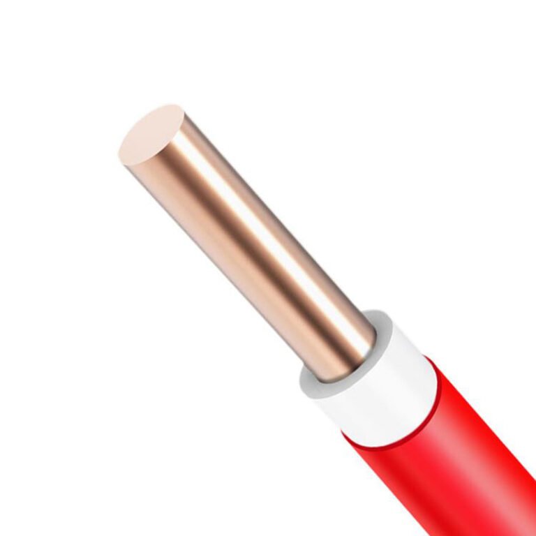
Conductor — stranded copper or aluminum wire, drawn and bunched to IEC 60228 Class 2 (or Class 5 for flexible applications). Copper carries roughly 60–65% of the global cable conductor market by value, mostly because of its superior conductivity and solderability. Aluminum is used where weight or raw material cost drives the decision, typically in overhead and large-section underground feeders. Same current rating in aluminum requires roughly a 1.6× larger cross-section than copper — worth factoring into conduit sizing.
Conductor screen — a semi-conductive layer applied over the conductor in MV and HV cables. It smooths out the electric field and eliminates air voids at the conductor surface that would otherwise cause partial discharge. Skipping or damaging this layer during installation is a reliable path toward premature insulation failure.
Insulation — XLPE (cross-linked polyethylene) dominates modern power cables because it operates continuously at 90°C conductor temperature and handles short-circuit temperatures up to 250°C. EPR (ethylene propylene rubber) is the alternative where flexibility or moisture resistance in harsh environments is paramount, such as mining trailing cables or offshore applications.
Insulation screen — the outer semi-conductive equivalent of the conductor screen. It keeps the electric field contained and uniform. Strippable vs. bonded screen is a real procurement decision for MV cables: strippable simplifies jointing in the field, bonded gives better long-term adhesion.
Metallic armor and outer sheath — Steel wire armor (SWA) handles direct burial and mechanical abuse. Aluminum wire armor (AWA) is preferred for single-core cables in AC systems to avoid eddy-current losses that SWA would cause. The outer sheath — usually PVC or HDPE — is the environmental barrier. HDPE is worth specifying for buried cables in aggressive soil chemistry; PVC is adequate for most indoor and tray installations but softens around 70°C ambient, so watch placement near hot process equipment.
Current-Carrying Capacity: Realistic Benchmarks
| Conductor | Insulation | Installation | Approx. Ampacity |
|---|---|---|---|
| 95 mm² Cu | XLPE 90°C | Free air, single circuit | 230–280 A |
| 95 mm² Cu | XLPE 90°C | Direct buried, 0.8 m depth | 195–240 A |
| 150 mm² Cu | XLPE 90°C | Free air, single circuit | 290–340 A |
| 150 mm² Al | XLPE 90°C | Free air, single circuit | 225–265 A |
| 240 mm² Cu | XLPE 90°C | Cable tray, touching | 340–400 A |
Figures per IEC 60502-1 methodology; actual values depend on ambient temperature, grouping factor, soil thermal resistivity for buried installations, and installation depth. Always run a derating calculation for your specific conditions — the table is a starting point, not a final answer.
IEC 60502-1 specifies construction and test requirements for power cables with extruded insulation rated from 1 kV to 30 kVTrue
IEC 60502-1 (latest edition 2004, with amendments) covers exactly this voltage range and is the primary international reference standard for medium-voltage power cables with XLPE or EPR insulation. It defines conductor requirements, insulation thickness, screen construction, and type test procedures.
Standards and Procurement Checklist
Key standards you’ll reference: IEC 60502 (1 kV–30 kV extruded insulation), IEC 60228 (conductor classes), BS 5467 (UK armored cables), and NEC Article 310 for North American ampacity and wiring method rules. Jinda’s power cable range is manufactured and tested to GB/T 12706, which aligns closely with IEC 60502 and covers conductor cross-sections from 1.5 mm² through to 630 mm² across LV and MV voltage classes.
Before issuing a purchase order, work through this checklist:
- Conductor material and cross-section (mm² or AWG/kcmil for NEC projects)
- Insulation material (XLPE vs. EPR) and rated conductor temperature
- Voltage class and whether screened construction is required
- Armoring type — SWA for multi-core buried, AWA for single-core AC circuits
- Short-circuit withstand requirement in kA·s (often overlooked until a protection study gets done)
- Flame-retardant or fire-resistant classification: IEC 60332-1/-3 for flame spread, IEC 60331 for circuit integrity under fire — two very different things that get confused regularly on project specs
An operational warning worth stating plainly: specifying a fire-resistant (FR) cable when the project actually needs a flame-retardant (FRT) cable, or vice versa, is one of the most common errors on commercial building specs. FR cables maintain circuit function during a fire. FRT cables resist flame propagation but do not guarantee function. They are not interchangeable.
Type 2 — Control Cables: Multi-Core Configurations, Shielding Options, and Automation Panel Wiring Rules
Control cables and power cables share the same basic construction logic — conductor, insulation, sheath — but they do completely different jobs, and confusing them in a panel specification is the kind of mistake that shows up weeks later as intermittent faults, nuisance trips, or a VFD throwing noise-related errors at 3 a.m.
The core distinction: a control cable carries command signals, status feedback, and interlock loops at currents typically well below 5 A. The conductors are small, often 0.5 mm² to 2.5 mm², and the voltage rarely exceeds 600 V. What the cable does need to handle is electromagnetic interference — because in any real industrial panel or cable tray, control cables run alongside 480 V motor feeders, contactor coils switching inductive loads, and variable-frequency drives that are essentially broadband noise generators by design.
Multi-Core Arrangements and Why the Numbers Look Odd
Standard core counts run 4, 7, 12, 19, 27, 37, and up to 61 in high-density configurations. The odd numbers aren’t arbitrary. A 7-core cable, for example, fits one twisted pair plus a drain wire plus additional signal cores — the geometry also packs more efficiently into a round cross-section with less interstitial void, which matters when you’re threading cables through conduit. Nineteen-core and 27-core cables are common in PLCs wiring to remote I/O clusters or in machine tool panels where the designer needs to minimize conduit runs. Specifying a 37-core rather than running three separate 12-core cables can reduce labor cost meaningfully on a large panel build, though it makes field troubleshooting harder if the cable isn’t clearly documented.
Shielding Architectures — Not All Shields Are Equal
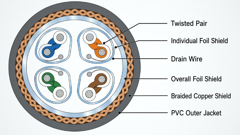
Three practical options exist: individual pair shielding, overall foil shield, and braided copper overall shield.
Individual pair shields (typically aluminum-polyester foil with a drain wire per pair) make sense when you have mixed signal types in the same cable — say, a 4–20 mA analog loop alongside discrete 24 V DC signals. The pair-level shield prevents crosstalk between channels. It adds cost and diameter, and terminating all those individual drain wires properly is genuinely tedious work; poorly terminated drain wires sitting ungrounded at one end defeat the purpose entirely.
An overall foil shield is lighter, cheaper, and adequate for many discrete I/O applications. A braided copper overall shield — typically at 85% or better optical coverage — is more robust mechanically and measurably better at high-frequency attenuation.
A braided copper shield at 85% coverage typically attenuates conducted electromagnetic interference by 40–60 dB across the 10 kHz to 100 MHz range relevant to industrial drive environments.True
This range is consistent with published shielding effectiveness data in IEC 62153-4 series and manufacturer test reports for industrial control cables. Actual attenuation depends on shield termination quality, frequency, and cable routing practice.
That 40–60 dB figure assumes the shield is properly terminated — continuous 360° termination into a metal cable gland or backshell, grounded at one end for low-frequency loops, both ends for high-frequency noise. In practice, a significant share of shielding failures in the field trace back to termination, not the cable itself.
Applicable Standards and Regional Color-Coding
IEC 60227 and IEC 60245 cover insulation requirements for PVC and rubber-insulated cables respectively. VDE 0293 (the German standard, widely adopted across European machine builders) sets core identification rules. NFPA 79 governs industrial machinery wiring in North America and has specific requirements for control circuit conductor sizing, overcurrent protection, and color coding that differ from CENELEC practice — notably, North American convention uses black for line conductors and white or gray for neutral, while European CENELEC harmonized color coding uses brown, black, and gray for phase conductors with blue for neutral. A panel being exported from Europe to a U.S. customer, or vice versa, needs explicit attention here. Mistaken assumptions about conductor color on a field-wired safety circuit are not a theoretical risk.
PVC vs. LSZH Sheath Selection
For most factory floor installations, standard PVC outer sheath is economical and performs well. The calculus changes in confined or poorly ventilated spaces — cable trays in offshore platform accommodation modules, data center under-floor runs, tunnel installations, and enclosed control rooms. PVC combustion produces hydrogen chloride gas, which is corrosive to electronics and acutely toxic in a fire scenario. LSZH (Low Smoke Zero Halogen) compound sheaths, tested under IEC 60754 and IEC 61034, reduce halogen acid gas emission by over 80% compared to standard PVC and produce substantially lower optical smoke density. The material costs roughly 15–30% more depending on compound grade and order volume, which is usually justifiable when personnel egress or equipment survival in a fire event is a real design consideration.
Jinda produces control cables in conductor sizes from 0.5 mm² through 6 mm² with core counts reaching 61, with options for individual pair shielding, collective foil shielding, or braided overall shielding — configurations used by automation OEMs supplying European packaging lines and Southeast Asian process plants where both IEC compliance and tight delivery windows are non-negotiable.
Type 3 — Instrumentation Cables: Signal Integrity, Pair Capacitance Limits, and Hazardous-Area Certification
Instrumentation cable has one job: get a weak signal from point A to point B without distorting it. That sounds simple until you’re running a 4–20 mA temperature loop 600 meters through a refinery that has a VFD cabinet every 30 meters and ground loops in three different process areas. Then it gets complicated fast.
What Instrumentation Cables Actually Carry
The signals involved are genuinely tiny — thermocouples generate millivolt-range EMFs (a Type K puts out roughly 40 µV/°C), and even the workhorse 4–20 mA current loop is susceptible to noise pickup if the cable isn’t properly constructed. FOUNDATION Fieldbus H1 and PROFIBUS PA add another dimension: these fieldbus protocols superimpose a digital signal on a 9–32 V DC bus at 31.25 kbit/s, and they are acutely sensitive to impedance mismatches caused by excessive cable capacitance.
This is why instrumentation cable is not just “small power cable.” Using a standard multi-core power cable for analog instrumentation because it was available on the shelf is one of the more expensive mistakes you can make in a DCS installation. The signals degrade, the loop doesn’t calibrate properly, and tracking down the problem — once the cable is already pulled through conduit — is miserable.
Capacitance Is the Governing Electrical Parameter
Mutual capacitance between conductors within a pair is typically specified at less than 100 pF/m for general 4–20 mA loops, and tighter — usually below 60 pF/m — for PROFIBUS PA. These limits aren’t arbitrary. Capacitance integrates over the cable run: at 80 pF/m over a 500 m run, you’re looking at 40 nF of capacitance, which affects signal rise time and, in fieldbus applications, creates reflections that corrupt bus communication beyond a critical segment length (typically around 1,900 m for PROFIBUS PA, but that assumes the cable meets the profile specification).
A practical benchmark: a 1.5 mm² individually shielded twisted pair running 500 m should show loop resistance below roughly 24–26 Ω and total capacitance below 50 nF to stay within the operating envelope of most transmitters and field devices. Push past those figures and you’re relying on the transmitter’s internal compensation to cover the gap — sometimes it will, sometimes it won’t, and you usually find out during commissioning rather than on the drawing board.
Construction: Why Individual Shielding Matters
The standard construction for process plant instrumentation cable is individually shielded twisted pairs (ISTP): each pair twisted at a controlled lay length, wrapped in a 100% coverage aluminum-polyester foil with a drain wire, and then the whole cable enclosed in an overall tinned copper braid. The individual shields isolate pair-to-pair crosstalk; the overall braid handles externally induced interference. For direct burial or mechanical protection in a live process environment, armored variants — steel wire armour (SWA) or aluminum wire armour (AWA) for weight-sensitive applications — are standard.
Temperature rating matters more than people think. A cable sitting on a pipe bridge in northern China or a Central Asian gas field will see −40°C in winter; process areas around heat exchangers can hit +80°C continuously. Specifying a cable rated to −40°C / +90°C is basic insurance.
Hazardous-Area Requirements: ATEX, IECEx, and Intrinsic Safety
In Zone 1 or Zone 2 gas atmospheres, instrumentation cable doesn’t just need to be robust — it needs to be part of a certified intrinsically safe (IS) circuit if that’s the protection concept being used. IEC 60079-14 governs the installation; IEC 60079-11 sets the entity parameters that define the cable’s maximum allowable capacitance and inductance in an IS loop.
This is where procurement gets genuinely technical. An IS loop has a certified maximum cable capacitance (Cc) and inductance (Lc) defined by the barrier or isolator manufacturer. The cable’s actual capacitance and inductance per meter, multiplied by the run length, must stay within those limits — with margin. ATEX or IECEx certification on the cable itself confirms it has been assessed for use in explosive atmospheres. Specifying “instrumentation cable” without checking whether it carries the relevant Ex certification for your area classification is an auditable gap in your hazardous-area documentation.
Exceeding a fieldbus cable's specified capacitance per meter limit over long runs will cause PROFIBUS PA segment communication errors.True
PROFIBUS PA segment length and device count limits are directly dependent on the cable's capacitance meeting the Type A profile specification (≤ 2 nF/km for some parameters). Higher capacitance loads the bus and reduces the maximum permissible segment length, consistent with Profibus International technical documentation and IEC 61158.
Procurement Checklist
Before raising a purchase order for instrumentation cable in any process plant application, these parameters need to be locked down:
| Parameter | Typical Specification | Why It Matters |
|---|---|---|
| Number of pairs | 1P, 2P, 4P, 8P, up to 20P+ | Determines cable OD, conduit fill, and termination space |
| Shielding | ISTP + overall braid | Individual shields prevent inter-pair crosstalk |
| Capacitance (pair-to-pair) | ≤ 100 pF/m (4–20 mA); ≤ 60 pF/m (PROFIBUS PA) | Governs maximum reliable run length |
| Conductor size | 0.5–1.5 mm² depending on run length | Affects loop resistance over long distances |
| Temperature range | −40°C to +90°C for demanding sites | Covers arctic installations and hot process areas |
| Hazardous-area certification | ATEX / IECEx Zone 1 or Zone 2 as required | Required for IS circuit documentation compliance |
| Armoring | SWA or AWA for direct burial or mechanical risk | Avoids cable damage in live process areas |
Get the capacitance figure from the manufacturer’s test report, not the datasheet header. Datasheets sometimes list a “nominal” figure; actual production variance can push a borderline cable over the limit.
Type 4 — Communication and Data Cables: Cat6 to Fiber Optic, Bandwidth Ratings, and Data Center Structured Cabling
The copper data cable family has a clear hierarchy, and specifying the wrong tier is surprisingly easy to do — especially on projects where the structured cabling budget gets squeezed late in design.
The Copper Data Cable Hierarchy
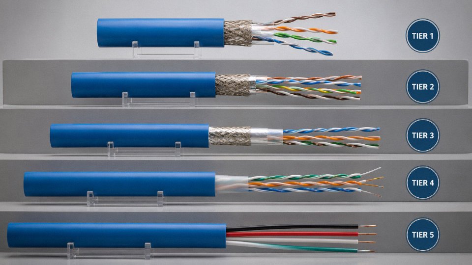
Cat5e handles 1 Gbps up to 100 m at 100 MHz and remains adequate for standard office drops, light industrial HMI links, and IP camera runs where bandwidth isn’t a constraint. Step up to Cat6 and you get 250 MHz bandwidth with tighter pair twisting and a central spline that reduces crosstalk — still rated for 1 Gbps at 100 m, though its effective ceiling at 10 Gbps drops to roughly 55 m under real plant conditions. That 55 m limit catches people off guard in data center row-to-row cabling when racks are spread across a large floor.
Cat6A changes the equation for 10GBase-T. Running at 500 MHz with shielded S/FTP construction, it suppresses alien crosstalk well enough to run the full 100 m at 10 Gbps. The foil-over-braid shielding adds weight and stiffness — pulling Cat6A through conduit in a tight ceiling plenum takes noticeably more labor than Cat6 — but for any new data center or industrial Ethernet backbone installed today, there’s little justification for specifying anything below Cat6A.
Cat8 (2000 MHz, 25–40 Gbps) is a short-reach cable by design, typically 30 m or less, intended for top-of-rack server-to-switch links. It’s not a structured cabling standard in the conventional sense; it’s more of a high-density data center interconnect.
Governing standards are TIA-568 (North American installations) and ISO/IEC 11801 (international and European projects). Both define channel performance, connector mating cycles, and installation tolerances. On export projects — particularly in the Middle East and Africa — specifiers routinely call out both standards in the same tender document.
Why Fiber Optic Outperforms Copper Beyond Certain Distances
Single-mode fiber (OS2, 9/125 µm) has an attenuation of roughly 0.18–0.22 dB/km at 1550 nm. That number doesn’t vary much with installation quality — which is one reason telecom backbone engineers prefer it. Below 10 km, multimode OM3 or OM4 (50/125 µm) is typically more cost-effective: transceivers are cheaper, and OM4 supports 10 Gbps out to around 400 m, 40 Gbps to about 150 m. For anything longer — campus backbone, inter-building runs, or any link where you expect bandwidth to grow in the next decade — specify single-mode from the start. Retrofitting a multimode backbone is a painful conversation to have three years post-installation.
OS2 single-mode fiber supports transmission distances beyond 10 km with losses of approximately 0.2 dB/km at 1550 nmTrue
This aligns with IEC 60793-2-50 specifications for OS2 single-mode fiber and is consistent with published attenuation values from major fiber manufacturers.
Coaxial Cable: Legacy, Not Obsolete
Coaxial cable still handles jobs that structured copper and fiber don’t address economically. RG-6 (75 Ω) is the standard for CATV, satellite distribution, and CCTV over distances up to a few hundred meters. RG-58 (50 Ω) persists in legacy CCTV and some industrial RF sensor links. Broadcast facilities running hardline coax for RF transmission use larger-diameter 50 Ω foam-dielectric types — attenuation on half-inch hardline runs around 3–5 dB per 100 m at typical broadcast frequencies, depending on frequency and dielectric quality. Mixing 75 Ω and 50 Ω components in the same run causes impedance mismatch and signal reflection; that mistake shows up as ghost images on analog feeds or elevated bit error rates on digital signals.
Data Center Structured Cabling and Fire Code Compliance
ANSI/TIA-942 and BICSI 002 define the physical infrastructure tiers for data centers, including cable routing, redundancy, and pathway separation. Fire jacket ratings matter more than most procurement teams realize until there’s an inspection. Plenum-rated (CMP) jackets use low-smoke, flame-retardant compounds and are required in air-handling spaces — including most raised-floor data centers where underfloor space is a return-air plenum. Riser-rated (CMR) is acceptable in vertical shafts between floors but not in plenum spaces. Using CMR cable in a plenum ceiling to save a few cents per meter is a code violation that fails occupancy inspection and, in a fire, produces significantly more toxic smoke.
Jinda produces armored fiber optic cables including ADSS (all-dielectric self-supporting) and direct-burial GYFTY designs, along with shielded data cables, for telecom infrastructure projects across the Middle East and parts of Africa where outdoor aerial and direct-burial deployments require mechanical protection beyond what a standard indoor cable provides.
Type 5 — Specialty and Flexible Cables: Mining, Offshore, Welding, and High-Flex Robotic Applications
Standard power and control cables are engineered for relatively predictable environments — fixed installations, controlled temperatures, the occasional vibration. Specialty cables exist because a significant portion of real industrial work happens nowhere near those conditions. A longwall mining machine dragging a trailing cable across abrasive ground, a subsea umbilical cycling through wave-induced tension off a production platform, a robotic welding arm making 400 strokes per hour — none of these applications can tolerate a cable built to ordinary specs. The failure modes aren’t nuisances; they’re production stops, safety incidents, and in some jurisdictions, regulatory shutdowns.
Mining Cables: Built for Punishment, Not Just Power
Heavy-duty mining trailing cables are among the most mechanically abused cables in industrial use. They’re dragged, crushed underfoot by equipment, exposed to water, coal dust, and methane-rich atmospheres — sometimes all at once. Construction typically uses thick rubber insulation and a robust rubber or polychloroprene outer sheath, with the whole assembly rated for continuous flexing under ground-drag conditions that would destroy a standard SWA cable within weeks.
Voltage ratings run 3.3 kV to 11 kV depending on the machine size and mine distribution system. Flame-retardant properties to IEC 60332-3 are non-negotiable in underground coal environments, and anti-static requirements follow from the obvious ignition risk. In the US, MSHA (Mine Safety and Health Administration) approval is a hard procurement requirement — not a preference. Specifying a cable without checking MSHA listing is a procurement error that gets caught at site acceptance, usually at the worst possible time. Australian operations work to AS/NZS 2802, which has its own thickness and test requirements that diverge from IEC 60502-4 in ways that matter when sourcing internationally.
Offshore and Subsea Cables: Corrosion, Pressure, and Dynamic Fatigue
Saltwater is extraordinarily hostile to cables. UV radiation at the surface, dynamic bending stress as a floating structure moves with swell, hydrostatic pressure at depth, and biofouling all combine to degrade materials that perform fine onshore. Offshore cables typically use double steel wire armor or polyester bedded armor, mud-resistant outer sheaths (usually polyurethane or a specialized compound), and construction verified by hydrostatic pressure testing — commonly to 300 m water depth, though riser and umbilical applications may demand considerably more.
Type approval from DNV or Lloyd’s Register is standard procurement language in this sector. Without it, offshore operators won’t accept the cable regardless of price. In practice, the certification process takes time, so procurement managers sourcing for offshore projects need to build that lead time into schedules — rushing it produces paper problems that delay installation contracts.
Welding and Festoon Cables: Flex Cycle Life Is the Specification
Welding cables are deceptively simple-looking but carefully engineered. The conductor is Class 6 fine-wire stranded per IEC 60228 — meaning hundreds of individual wires bundled to allow extreme flexibility — surrounded by natural rubber or polychloroprene insulation rated typically to 600 V and 105°C. Conductor sizes range from roughly 16 mm² up to 120 mm² for heavy welding equipment. The 100,000+ flex cycle rating sounds abstract until you watch a fabrication shop’s welding cable fail at the neck after three months because someone substituted a cheaper, less flexible type.
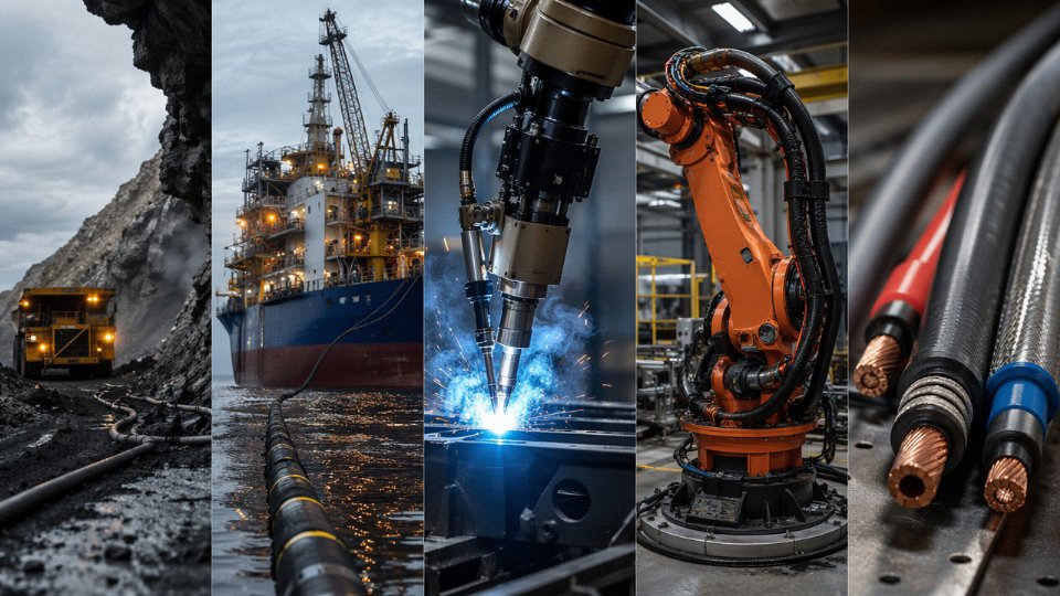
Festoon cables used in crane and conveyor pendant systems face similar demands — constant loop travel, sometimes in outdoor environments with ozone exposure.
High-Flex Robotic Cables: Ten Million Cycles Is the Starting Point
Cables installed in cable carriers (energy chains) on robotic arms and CNC equipment face a completely different stress profile from almost any other application. The cable bends at the same point, in the same direction, thousands of times per day. PUR (polyurethane) outer jackets handle oil splash and abrasion from the chain guides. Testing to DIN EN 50396 and UL 21 validates the construction, but the design detail that matters most in practice is the fine-wire stranding geometry and how the individual conductors are laid up — cheap copies of name-brand robotic cable fail in the 1–2 million cycle range rather than reaching the 10 million-plus the application demands. The cost difference between a proper robotic cable and a substandard one is small per meter; the cost of a failed cable inside a robotic cell during production is not.
What to Specify When Sourcing Specialty Cables
Flexible and specialty cables are the category where procurement teams most often under-specify, because the instinct is to match voltage and cross-section and stop there. At minimum, your purchase specification should state: minimum bend radius (typically 7.5× OD for flexible types, 12× OD or more for armored cables), rated flex cycle life, temperature range (both ambient operating and conductor temperature), and chemical resistance profile — oil, ozone, and UV exposure each require different jacket compounds and can’t be assumed from a generic “flexible cable” description.
Mining trailing cables used underground in MSHA-regulated US mines must carry MSHA approval; IEC certification alone does not satisfy US regulatory requirements.True
MSHA conducts its own approval program under 30 CFR Part 18 and related regulations. IEC 60502-4 or European certifications are not accepted as equivalent substitutes for US underground coal mine applications.
Getting this category right is largely a documentation and lead-time discipline. The cables exist; the certified, properly specified versions of them exist. The procurement risk is substitution — accepting a product that looks similar on a data sheet but lacks the mechanical testing, certification, or construction quality the application actually needs.
Side-by-Side Comparison: Matching the Five Cable Types to Industry Applications and Key Selection Parameters
The comparison table below is the kind of single-page reference that should be pinned above every procurement desk. It won’t replace a full specification review, but it stops the most expensive early-stage mistakes — the ones where the wrong cable family gets quoted before anyone notices.
The Five-Type Reference Table
| Cable Type | Typical Voltage Range | Conductor Size Range | Key Standards | Primary Industries | Distinguishing Feature |
|---|---|---|---|---|---|
| Power | 0.6/1 kV up to 132 kV+ | 1.5 mm² to 1,000 mm² and above | IEC 60502, IEC 60228, ICEA S-93-639 | Utilities, construction, industrial plants | Current-carrying capacity; armoring for mechanical protection |
| Control | Up to 600 V (typically 300/500 V) | 0.75 mm² to 6 mm² | IEC 60227, VDE 0250, UL 508 | Automation, panel building, process control | Multi-core count (up to 61 cores); overall or individual screening |
| Instrumentation | Up to 300 V signal level | 0.5 mm² to 2.5 mm² (pairs/triads) | IEC 60092-350, ISA-S5.1, IEC 60079 series | Oil and gas, chemical, power generation | Tight capacitance control (typically ≤ 100 pF/m); ATEX/IECEx certification |
| Communication/Data | Low voltage, signal level | AWG 22–26 (copper), varies for fiber | TIA-568, IEC 11801, ITU-T G.652 | Data centers, telecoms, IT infrastructure | Bandwidth rating; insertion loss; fiber attenuation per km |
| Specialty/Flexible | Varies widely by type | 0.5 mm² to 300 mm² | IEC 60245, IEC 62440, AS/NZS 1802 | Mining, offshore, welding, robotics | Mechanical endurance — flex cycles, crush resistance, chemical jacket resistance |
Conductor sizes and voltage classes shift depending on national grid standards, so always cross-check IEC figures against local utility codes before issuing a final BOM.
Six Real-World Scenarios Mapped to Cable Type
Offshore oil platform pulls from three cable families simultaneously. Topside power distribution uses armored 6.35/11 kV XLPE cables with a corrosion-resistant outer sheath — standard PVC simply degrades in the salt-laden atmosphere within a few seasons. The instrument loops back to the control room run in individually screened, ATEX Zone 1-rated pairs. Umbilical trunkings in the splash zone use specialty cables with a polyurethane jacket, because nothing else holds up against the mechanical abrasion and intermittent seawater immersion.
Smart factory automation line runs all three “non-specialty” types in close proximity. Power feeds the servo drives and main switchgear. Control cables carry the 24 V DC and relay logic signals. And Cat6A or fiber trunks tie the SCADA nodes and vision systems together. Physical separation matters here — more on that shortly.
Urban underground distribution is almost entirely medium-voltage XLPE, typically 8.7/15 kV or 12/20 kV depending on the national grid tier. Single-core or three-core armored designs with longitudinal water-blocking tapes are standard for metropolitan duct runs. Skipping water-blocking on a below-water-table installation is a decision that shows up as a splice failure two to four years later.
Data center build-out lives in the data/fiber column almost exclusively. Backbone runs are OM4 or OS2 fiber; horizontal structured cabling is Cat6A for anything requiring PoE++ at long reach. The only power cable a cabling designer really touches here is the branch circuit feeding the rack PDUs — and specifying that in aluminum instead of copper at this scale is an argument worth having with your electrical contractor.
Mine site expansion means flexible trailing cables with ground-check conductors, rated for continuous flex, trailing-on-ground mechanical abuse, and whatever voltage the dragline or continuous miner demands — often 3.3 kV or 6.6 kV in medium-voltage trailing designs. Using a standard SWA power cable here is a genuine safety failure waiting to happen.
Process chemical plant instrumentation is where ATEX certification is non-negotiable, not optional. A standard screened instrumentation cable without a certified outer sheath runs afoul of Zone 2 area classification the moment someone signs the hazardous-area drawing.
Three Specification Mistakes That Show Up Repeatedly
Under-specifying armoring for direct burial. Wire-armored cable (SWA or STA) is specified for a reason — mechanical protection against ground movement, rodent damage, and accidental dig-ins. Unarmored cable in direct burial survives until the first ground-works crew shows up. The repair cost on a 33 kV feeder that goes out during site construction typically runs to multiples of the original cable cost, to say nothing of the schedule impact.
Ignoring capacitance specification on long instrumentation runs. This one is subtle and engineers get burned by it more than they expect. On a 500-meter 4–20 mA loop, a cable with 150 pF/m capacitance will cause enough signal sluggishness to trip out fast-responding safety instruments that are looking for loop response times under a certain threshold. The IEC 61158 fieldbus standards set capacitance limits explicitly — exceeding them on a Profibus or HART segment degrades communication reliability in ways that are genuinely hard to diagnose after commissioning.
Exceeding the maximum capacitance per-unit-length limit specified in IEC 61158 for fieldbus cable can cause communication errors and reduced segment length capacity.True
IEC 61158 and the Profibus installation guidelines from the Profibus & Profinet International organization specify maximum capacitance values (typically around 30 nF per segment depending on baud rate). Cable with higher capacitance per meter reduces the achievable segment length and can cause reflections and framing errors.
Using standard PVC control cable where LSZH is mandatory. In tunnels, data centers, offshore platforms, and most European rail and public-building projects, Low Smoke Zero Halogen sheath compounds are specified by the fire safety authority — often under IEC 60332-3 and IEC 61034. Standard PVC releases hydrogen chloride gas in a fire. That’s toxic to occupants and corrosive to any electronics in the building that survives. The cable cost delta between PVC and LSZH is small. The regulatory and liability exposure for substituting incorrectly is not.
A Four-Question Decision Framework
When a procurement team or project engineer is staring at an application and doesn’t know where to start, these four questions get to the right cable family faster than any catalog.
1. What is the primary function? Power delivery, signal/measurement, data communication, or some special mechanical duty (flexibility, chemical resistance, extreme temperature)? The answer narrows the field immediately.
2. What is the operating environment? Indoor conduit, outdoor cable tray, direct buried, submerged, mobile equipment, or classified hazardous area? Each environment adds jacket, armoring, or certification requirements that eliminate options.
3. What voltage and current are involved? A 24 V DC control signal and a 33 kV feeder cable are not in the same conversation. Current rating also drives conductor cross-section, which drives physical size and weight — both of which matter on offshore platforms and in dense cable trays.
4. Are there regulatory or certification requirements? ATEX, IECEx, UL listing, CPR (Construction Products Regulation in the EU), Lloyd’s Register for marine use. These aren’t optional checkboxes — they determine which products are legally installable in a given jurisdiction or application.
Handling Mixed-Use Cable Corridors
On large infrastructure projects — process plants, substations, tunnel systems — it is common to route multiple cable types through shared trenches or trays. This is where EMI crosstalk becomes a physical installation issue, not just a design concern.
The IEC 61000-5-2 installation guideline recommends a minimum 200 mm physical separation between power cables and signal or instrumentation cables where both run in parallel over significant distances. Where space genuinely doesn’t allow that separation, individually screened instrumentation cables with a properly terminated drain wire provide a workable alternative — but the screen must be grounded at one end only (typically the control room end) to avoid creating a ground loop that introduces more noise than it removes. In practice, many sites ignore this rule during the early construction phase when the tray routing is still fluid, and then spend weeks during commissioning chasing unexplained 4–20 mA drift and spurious relay operations back to exactly this cause.
The table and framework above don’t replace a full cable schedule review. But they do front-load the right questions — and that is where most specification errors are actually prevented.
How to Evaluate a Cable Manufacturer: Quality Certifications, Factory Audits, and Supply Chain Reliability Indicators
Buying cable from an unfamiliar supplier is one of those procurement decisions that looks low-risk until something fails — and when cable fails in a commissioned plant, the cost is rarely just the cable itself. It’s the rewiring labour, the production downtime, the insurance conversation. Getting supplier evaluation right upfront is cheaper than any of those outcomes.
Certification Tiers: Product-Level vs. Factory-Level
Most buyers ask for “certifications” and accept whatever PDF arrives. That’s not enough. There are two distinct layers you need to verify, and they tell you different things.
Product-level type test certificates — think third-party test reports against IEC 60502, IEC 60227, or IEC 60332 issued by labs like KEMA, DEKRA, TÜV, or SGS — confirm that a specific cable construction actually performed to spec under controlled test conditions. Factory-level system certifications (ISO 9001 for quality management, ISO 14001 environmental, ISO 45001 occupational safety) tell you whether the processes producing that cable are controlled and auditable day to day. A factory can hold ISO 9001 and still ship a bad drum if their raw material intake inspection is weak. A factory with clean third-party type test reports but no QMS can get you one good batch and then drift. You want both, with current validity dates — ISO certificates lapse, and a certificate that expired eight months ago is not a minor paperwork issue.
What a Meaningful Factory Audit Actually Checks
If you’re sourcing at volume — say, a multi-megawatt solar project or a refinery expansion — a desk audit of certificates is not sufficient. The checkpoints that reveal real manufacturing discipline are less glamorous than the marketing brochure.
Raw material traceability matters more than most buyers realise. Ask to see copper rod sourcing records and purity logs (oxygen-free copper for high-flex applications is not interchangeable with standard ETP rod, and a supplier who can’t show you the incoming material certificates probably isn’t tracking it). Conductor die calibration logs tell you whether conductor cross-sections are being held to IEC tolerances or drifting over a shift. Insulation extrusion temperature records — boring to read, critical to outcome — show whether the XLPE or PVC compound is being processed within the compound manufacturer’s specified window; out-of-window extrusion degrades long-term insulation resistance. Spark test voltage settings should be verified: for standard LV insulation the spark tester is typically set at around 6 kV AC, and a factory that can’t tell you their setting without checking is a flag. Finished-goods test reports should cover conductor resistance, insulation resistance, and voltage withstand per IEC 60502-1 Annex B at minimum — and the reports should be drum-specific, not generic batch summaries.
Shandong Jinda Special Cable Group Co., Ltd. maintains third-party product type test reports and holds current ISO 9001, ISO 14001, and ISO 45001 certifications across its production operations.True
Jinda's certification portfolio covers both product-level performance verification and factory-level management system requirements, consistent with the dual-tier evaluation framework described above.
Delivery Reliability: Lead Times, MOQs, and Warehouse Arrangements
For standard LV power cable in stock cross-sections, a competent manufacturer should be able to confirm production lead times in the 15–30 day range. Custom constructions — armoured instrumentation cables with specific pair counts, offshore-rated flexible cables, anything requiring a non-catalogue compound — typically run 45–75 days depending on compound availability and drum logistics. Those numbers assume no major material supply disruptions; factor in seasonal effects on copper rod pricing and shipping container availability, both of which have bitten projects badly in recent years.
MOQ varies significantly. Spot purchases of a few hundred metres are handled differently from project procurement of tens of kilometres. For long-term supply partnerships, asking about consignment stock or bonded warehouse arrangements is worth the conversation — a supplier with the production scale and financial stability to hold buffer stock for your region is a meaningfully different partner than one running order-to-order.
Jinda operates five production bases across China with a combined manufacturing footprint of 470,000 m², and employs over 1,000 people across production, R&D, technical support, and after-sales functions. That scale isn’t mentioned as a boast — it’s relevant because it means production scheduling flexibility, spare machine capacity, and an R&D centre capable of handling non-standard specifications without outsourcing the engineering problem to someone else.
Verifying Export Capability and Support Depth
Active supply into 50+ countries, with established relationships across the Middle East, Southeast Asia, Africa, and Europe, indicates a supplier that has navigated customs documentation, ISPM 15 heat-treated wooden drum requirements, and dual-language technical documentation — the kind of operational detail that delays shipments when it’s missing. The ability to support third-party inspection by a customer-nominated body (SGS, Bureau Veritas, Intertek) without friction is itself a qualification signal.
A practical due-diligence checklist before awarding an order: confirm ISO certificates carry current validity dates; request a production capacity statement for your cable type; review drum-specific test reports, not generic samples; verify packing standard and export marking compliance; and clarify warranty terms in writing, including what happens with a failed drum discovered after installation rather than at goods receipt. That last one tends to reveal a lot about a supplier’s actual confidence in their product.
Frequently Asked Questions About the Five Types of Cable
Can I use a power cable instead of a control cable to carry control signals?
Technically, yes — for a simple on/off pilot circuit at low current, a power cable will carry the signal. But “it works” and “it’s correct” are two different things. Power cables have no twisted pair geometry, no individual core shielding, and no controlled capacitance between conductors. In a PLC input card or a relay logic panel, that means you’re exposing low-level signals to coupled noise from adjacent power conductors, especially in a busy cable tray. NFPA 79 explicitly requires segregation of control wiring from power conductors in machinery panels. IEC 60204-1 carries similar intent. Skip that rule, and intermittent faults during drive acceleration — when switching noise spikes — will have your maintenance team chasing ghosts for days. Use the right cable type from day one.
What is the difference between armored cable and shielded cable?
These terms get conflated constantly, and they describe completely different functions. Armoring — steel wire armor (SWA) or aluminum wire armor (AWA) — is a mechanical layer. It resists crush loads, rodent attack, and incidental digging damage. Shielding is an electromagnetic layer: a foil wrap or braided conductor that diverts high-frequency interference away from the signal cores. A cable can have both, and in demanding instrumentation runs — say, a thermocouple cable running through a cable tray inside a petrochemical plant — you often want both. The armor protects the cable physically; the individual pair shields keep your 4–20 mA signals clean.
Is XLPE insulation better than PVC for power cables?
For most medium- and high-voltage applications, yes. XLPE’s continuous operating temperature is 90°C versus 70°C for standard PVC, which translates directly into higher allowable current for a given conductor cross-section — roughly 10–15% more ampacity depending on installation conditions. At medium voltage, XLPE’s dielectric losses are meaningfully lower, and its moisture resistance holds up better in damp or direct-burial environments. PVC isn’t obsolete, though. For indoor LV wiring below 70°C ambient where cost matters and the circuit isn’t heavily loaded, PVC remains practical and cheaper. The error is specifying PVC on a circuit that routinely runs near its thermal limit.
How do I calculate conductor size to avoid excessive voltage drop?
For single-phase circuits: V_drop = (2 × L × I × ρ) / A. For three-phase: V_drop = (√3 × L × I × ρ) / A. Here, L is the one-way cable length in meters, I is load current in amperes, ρ is resistivity (0.0175 Ω·mm²/m for copper; roughly 0.028 for aluminum), and A is conductor cross-section in mm². IEC and NEC guidelines generally target less than 3–5% voltage drop at full load — the tighter end applies to sensitive equipment like variable-speed drives or instrumentation power supplies. Long rural distribution runs and large motor feeders are where engineers most often undersize conductors on first pass.
What does LSZH mean, and when is it mandatory?
Low Smoke Zero Halogen. During a fire, a standard PVC jacket releases hydrogen chloride and dense black smoke, both of which slow evacuation and damage electronics. An LSZH jacket sharply limits both. It’s not optional in underground rail, road tunnels, offshore platforms, hospitals, or any enclosed public space where occupants may not be able to exit quickly. The relevant standards are IEC 60332-3 (flame propagation), IEC 61034 (smoke density), and IEC 60754 (halogen acid gas emission). Specifying standard PVC in these environments isn’t just a performance risk — in many jurisdictions it’s a compliance failure.
LSZH cable is mandatory in offshore platforms and underground rail applications under IEC 60332-3 and IEC 61034.True
IEC 60332-3 covers flame propagation for cables installed in bunches; IEC 61034 measures smoke density during combustion. Both standards are routinely invoked in offshore and transit project specifications globally.
How long does a properly installed direct-burial cable last?
A UV-stabilized, SWA-armored cable with HDPE or MDPE outer sheathing, laid at 600–900 mm depth per IEC 60364-5-52 and installed in conduit where route disturbance is likely, should realistically serve 30–40 years. What erodes that figure: aggressive soil chemistry (low pH, high sulfate content), repeated thermal cycling on heavily loaded circuits, and mechanical disturbance from later excavation works nearby. In practice, cables pulled through conduit outlast direct-buried cables almost every time, simply because re-pulling is possible if the outer sheath is compromised.
Does Jinda supply sample lengths before a bulk order?
Yes. Jinda can provide sample drums or cut lengths for pre-qualification testing prior to bulk commitment. Buyers should submit those samples to an accredited third-party laboratory — conductor DC resistance per IEC 60228, insulation resistance, and high-voltage withstand are the minimum tests worth running. This is standard procurement hygiene for any critical infrastructure project, regardless of supplier. Getting test data before a container ships is always cheaper than managing a nonconformance after.
Ordering, Customization, and Global Logistics: Working With Jinda as Your Long-Term Cable Supplier
If you’ve read this far, you’re likely past the “what cable do I need” stage and into the harder question: where do I actually source it, reliably, at the right specification, without the project schedule blowing up mid-shipment? That’s where manufacturer selection stops being abstract.
What Jinda Produces Across Its Five Factories
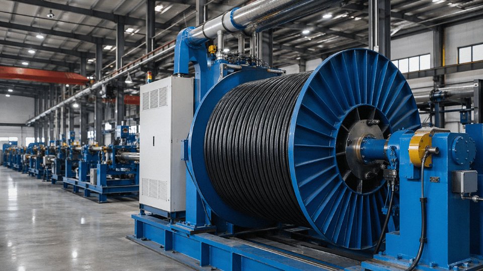
The standard product range covers low-voltage power cables at 0.6/1 kV, medium-voltage cables up to 35 kV, control and instrumentation cables in multi-pair and multi-core configurations, armored and unarmored data cables, and specialty types — mining cables, fire-resistant and fire-survival cables, LSZH variants, and high-flex designs for robotic and continuous-flex applications. Five production bases spread the manufacturing load, which matters practically: if one line is running a long scheduled production run for another customer, a second facility can absorb your order without the 4–6 week queue that trips up single-factory suppliers. Redundant capacity is one of those things that sounds like marketing until your commissioning date slips.
Customization: What’s Actually Adjustable
Conductor material is copper or aluminum. Cross-sections run from 0.5 mm² up to 630 mm², though in practice the upper end — anything above roughly 300 mm² — carries longer lead times because large-die tooling has to be scheduled, usually 3–5 extra working days depending on current line loading.
Insulation material choices include PVC, XLPE, EPR, and LSZH. The choice isn’t cosmetic — XLPE handles higher sustained conductor temperatures (typically 90 °C continuous versus 70 °C for standard PVC), and EPR suits flexible applications where XLPE would fatigue and crack. LSZH is increasingly required in confined spaces: offshore platforms, tunnels, public buildings.
Shielding configuration, armoring type (SWA, STA, wire braid, or none), and outer sheath color are all specifiable. Sheath color matters more than some buyers expect — yellow outer sheaths for medium-voltage in some Middle East projects, red fire-resistant cables in certain European installations, project-specific color codes in petrochemical plants. Custom sheath printing is available: project name, voltage rating, sequential meter marking. For long cable runs where installers need to track footage, sequential meter marking on the sheath saves real time on-site and reduces mis-cutting waste.
Drum length is specifiable within reason. Standard export drums follow IEC 60104. For large infrastructure projects, requesting specific drum lengths matched to your cable route plan avoids mid-run joints that add both labor cost and potential failure points.
The Order Process, Without the Surprises
Submit a technical inquiry with your cable schedule or BOQ. Jinda’s engineering team reviews it, flags any conflicts (a specified cross-section that doesn’t match the rated current for the nominated insulation, for example), and returns a confirmed cable schedule with lead time. Formal quotation follows. Samples are available if required before full order commitment — sensible for any specification you haven’t bought before.
Once a purchase order is placed, production moves through defined QC hold points: incoming conductor resistance check, insulation material melt flow index test, in-process spark testing at every extrusion line, and final routine electrical tests per IEC 60502-1 covering conductor resistance, high-voltage withstand, and insulation resistance. Third-party witness testing by SGS, Bureau Veritas, or Intertek can be arranged if your project specification or client requires it.
Jinda performs in-process spark testing at each extrusion line during production.True
Spark testing at the extrusion stage is a standard in-process quality control method for detecting insulation defects before cables are further processed or wound onto drums. This is consistent with IEC and industry manufacturing practice for insulated cables.
Documentation and Shipping
Standard export documentation includes Certificate of Origin, packing list, commercial invoice, material test certificate, and IEC-compliant test reports. For markets requiring ISPM 15 timber compliance — Australia, the US, and several others — fumigation certificates and phytosanitary certificates are available. Incoterms options cover FOB, CIF, and DDP, which is worth confirming early if your procurement policy locks in a specific term.
Shipment goes by FCL or LCL for standard sea freight, or air freight for urgent partial orders, though air freight for cable drums is expensive enough that it’s only worth considering for small-quantity emergency pulls.
Buyers with active projects can submit a cable schedule to Jinda’s international sales team and expect a turnaround quotation within 48 business hours. For projects with multi-year cable procurement plans, fixed-price supply agreements are available — a reasonable hedge when copper prices are moving.