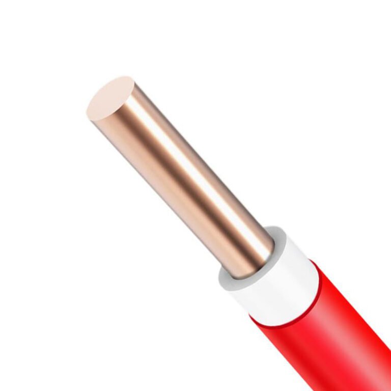
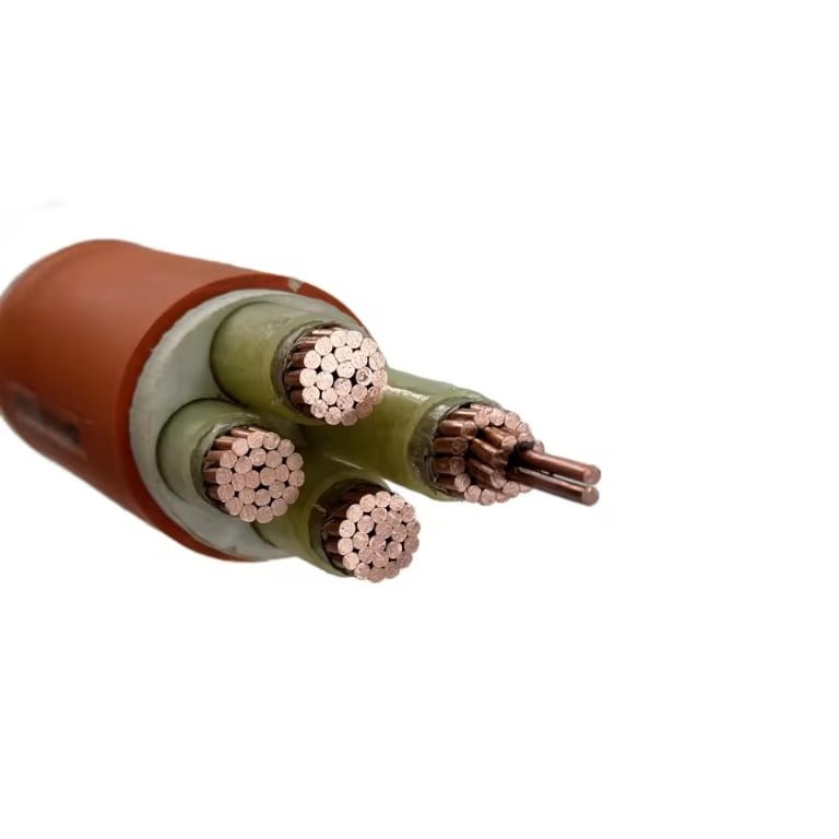
Pick the wrong cable type for an application and you rarely find out immediately — you find out six months later when insulation cracks in a high-flex zone, or three years in when a direct-burial run corrodes and takes a production line offline for two days. That’s not a theoretical risk. Replacement costs, unplanned downtime, and re-pulling cable through conduit already buried in concrete are all preventable expenses that trace back to a single procurement decision made without enough specificity. Getting the classification right at the design stage is the cheapest intervention available.
The four fundamental types of cable are: power cable, control cable, instrumentation cable, and communication cable. Each is defined by its conductor class, insulation system, and the electrical environment it’s built for. Choosing among them depends on voltage level, signal sensitivity, mechanical duty, and the installation environment — not just what happens to be in stock.
What makes this classification genuinely useful — rather than just a textbook sorting exercise — is that the boundaries between types aren’t always clean on a real plant floor. A single cable tray might carry all four, and the consequences of mixing up a control cable with an instrumentation cable in a noise-sensitive loop are exactly the kind of fault that takes days to diagnose. Understanding what distinguishes each type, structurally and electrically, is what separates a cable schedule that works from one that creates problems nobody budgeted for.
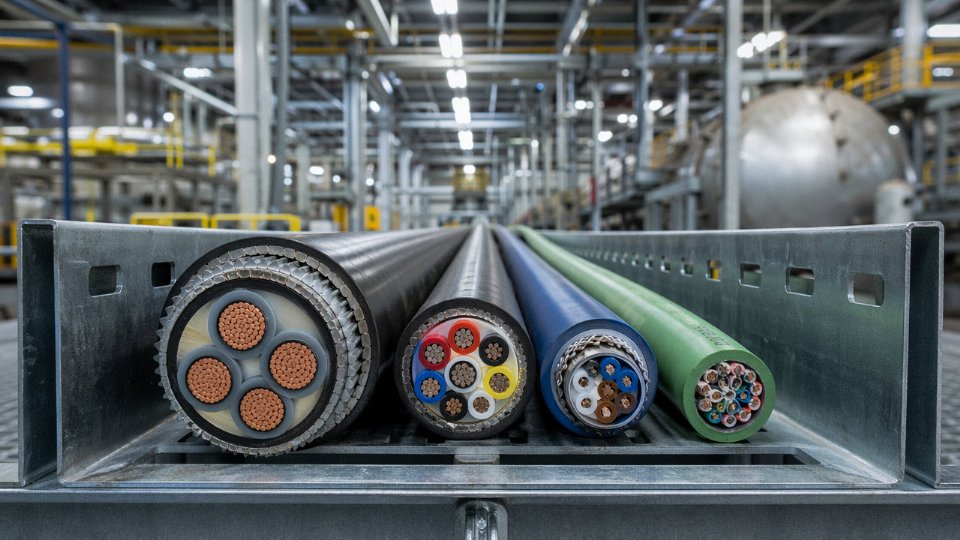
Type 1 — Power Cables: Construction Layers, Voltage Classes, and Conductor Choices
Power cables do one thing: move energy from a source to a load reliably, without overheating, arcing, or degrading prematurely. That sounds simple until you’re specifying a 33 kV feeder for a substation extension or trying to figure out why a buried distribution cable failed after seven years instead of thirty. Getting the construction layers and voltage class right at the procurement stage is where most of the real engineering happens.
Voltage Classes and What They Actually Mean for Specification
The industry segments power cables into four broad tiers. Low voltage covers up to 1 kV — the cables feeding motor control centers, lighting panels, and most factory distribution. Medium voltage runs from 1 kV to 36 kV and handles primary distribution feeders, wind turbine step-up connections, and industrial plant ring mains. High voltage spans 36–220 kV; you’re in transmission territory here, usually utility-grade projects. Extra-high voltage above 220 kV is a specialized segment — fewer suppliers, longer lead times, and procurement processes that look nothing like a standard cable order.
Each tier demands a different construction. Buying an LV-spec cable and attempting to use it in an MV application is an obvious failure mode, but subtler mismatches — like using an LV-rated outer jacket on an MV cable laid in a shared duct with high ground temperatures — cause slow, invisible damage that doesn’t show up until a fault.
Layer-by-Layer Construction
Start at the center. The conductor is either solid or stranded copper or aluminum, classified under IEC 60228 from Class 1 (solid, fixed installations) through Class 6 (highly flexible, portable equipment). For most fixed power installations, Class 2 stranded copper or aluminum is the standard choice. Copper dominates where current density matters in tight conduit runs; aluminum is common in larger cross-sections above roughly 120–150 mm² where weight and material cost drive the decision. Globally, copper conductors account for somewhere in the 60–65% range of installed cable volume, with aluminum taking most of the remaining share — though that balance shifts noticeably by region and voltage class.
Surrounding the conductor in MV and HV cables is a semiconducting conductor screen, which smooths the electric field gradient and prevents local stress concentration at stranding gaps. This layer is easy to overlook in a datasheet review but critical in MV joints — damage it during termination and you’ve introduced a future failure point.
Insulation is where the real material engineering sits. XLPE (cross-linked polyethylene) handles continuous operating temperatures up to 90°C and short-circuit temperatures up to around 250°C, with dielectric strength typically in the 20–35 kV/mm range depending on compound grade and processing quality. EPR (ethylene propylene rubber) runs at similar continuous temperatures but outperforms XLPE in two specific conditions: low-temperature flexibility (relevant for Arctic installations or outdoor winter handling) and resistance to water treeing in wet or flooded duct environments. In practice, XLPE is the default for most MV and HV projects; EPR shows up in offshore, mining, and northern-climate applications where flexibility or moisture exposure justifies the cost premium.
Beyond the insulation screen comes the metallic sheath — lead, corrugated aluminum, or copper tape depending on the application — followed by armor. Steel wire armor (SWA) is the workhorse for buried cables in most markets. Aluminum wire armor (AWA) is preferred when eddy current losses in single-core circuits are a concern. Wire braid armor handles flexible or lightly mechanical-protected runs. The outer jacket, usually PVC or HDPE, is the final barrier against UV, ground chemicals, and mechanical abrasion.
Conductor Sizing: Where Engineers Spend the Most Time
Current-carrying capacity varies with installation method, soil thermal resistivity, ambient temperature, and grouping. A 240 mm² copper XLPE medium-voltage cable in free air typically carries somewhere in the 430–490 A range — the exact figure depends on ambient temperature and whether it’s trefoil or flat formation. Burial in soil pulls that number down by 15–25% depending on soil resistivity, which itself varies seasonally in clay-heavy ground. Bundling multiple cables together without applying derating factors is a recurring cause of insulation aging failures in industrial plants; the IEC 60287 series covers the calculation methodology in more detail than most procurement specs bother to reference.
Voltage drop over long MV runs matters more than many plant engineers expect, especially for motor starting on feeders longer than 300–400 m. Running the voltage drop calculation at motor-start current — not just full-load current — occasionally forces an upsize from 95 mm² to 150 mm² even when thermal ratings look adequate.
Standards That Govern What You Buy
IEC 60502-1 covers LV power cables; IEC 60502-2 covers MV up to 30 kV. HV cables above 36 kV fall under IEC 60840. Projects in China reference GB/T 12706, which aligns closely with IEC 60502 but has some construction differences worth checking against your project spec. UK and Commonwealth projects often specify BS 5467 (LV armored) or BS 6622 (MV). Mixing standards on a single project creates termination and testing headaches — if your switchgear is type-tested to IEC and your cable spec defaults to BS, someone needs to verify compatibility before cable is pulled.
XLPE insulation has a higher continuous operating temperature than PVC insulation for power cable applicationsTrue
XLPE is rated for 90°C continuous operation versus 70°C for standard PVC insulation under IEC 60502 and related standards, which is why XLPE has largely displaced PVC in MV and HV power cable construction.
Jinda’s power cable production lines span LV through HV voltage classes across its five manufacturing bases, with production capacity scaled for bulk project orders — the kind of volume and lead-time consistency that matters when you’re sourcing cable for a large infrastructure or industrial project rather than filling a maintenance shelf.
Type 2 — Control and Instrumentation Cables: Signal Integrity, Shielding Architectures, and Loop Accuracy
Control and instrumentation cables are often lumped together in spec sheets, which causes real problems on the plant floor. They share some construction DNA — multi-core, small conductors, screened — but their jobs are fundamentally different, and specifying one where you need the other will cost you.
Control Cables vs. Instrumentation Cables: Not the Same Thing
Control cables carry switching and command signals: the 24 V DC pulse that tells a motor starter to close, the relay output that trips a valve actuator, the hardwired interlock between a PLC output card and a solenoid. Conductors typically run 0.75–6 mm², rated 300/500 V or 450/750 V depending on the application, with core counts anywhere from 4 to 40-plus. The signal level is relatively robust — tens of milliamps, multiple volts. A bit of noise pickup matters less.
Instrumentation cables are a different animal. They carry small analog signals: 4–20 mA process loops, millivolt-level thermocouple outputs, HART superimposed on a 4–20 mA carrier, Foundation Fieldbus at 31.25 kbps. Conductors are 0.5–1.5 mm², and in some cases the entire information content of a measurement is encoded in a signal swing of maybe 16 mA — roughly 0.8–1.6 V across a 50–100 Ω load. Introduce a few millivolts of coupled noise and you’ve degraded a precision flow measurement by a meaningful fraction of its span. That’s not a theoretical concern; it shows up as erratic PID behavior or spurious alarms that operators start ignoring, which is its own kind of hazard.
Why Noise Immunity Dominates the Design
Heavy industrial environments are electrically hostile. Variable frequency drives generate switching transients in the 2–20 kHz range and above. Large transformers radiate 50/60 Hz fields. Welding equipment produces broadband impulse noise. Running instrumentation cables in the same tray as VFD output cables — something I’ve seen done on tight-budget retrofits — is asking for trouble, even with a screen.
The shield is the primary defense, but shield architecture matters more than most procurement specs acknowledge.
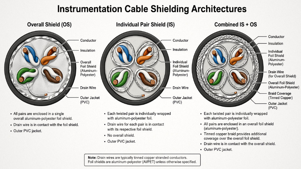
An overall shield (OS) — a single aluminum-polyester foil or tinned copper braid wrapped around the entire cable — attenuates common-mode interference entering the cable from outside. Typical rejection is roughly 20–35 dB at 50 Hz and 40–60 dB at 1 MHz, depending on coverage percentage and drain wire continuity. It works for simple single-loop runs where crosstalk between pairs isn’t the concern.
Individual pair/triad shielding (IS) puts a separate foil around each twisted pair or triad. This blocks inter-pair crosstalk — critical in multi-pair cables where, say, a 4–20 mA loop from a temperature transmitter could otherwise contaminate an adjacent thermocouple pair. IS alone gives comparable common-mode rejection to OS but dramatically better differential isolation between circuits.
The IS+OS combined architecture is standard for oil and gas multi-pair trunks and DCS marshalling cables. It’s heavier and costs 15–40% more than OS-only cable (the premium depends on pair count and conductor size), but in a 200-pair instrument cable running through a process unit with multiple noise sources, it’s the only architecture that reliably holds loop accuracy.
Individual pair shielding prevents inter-pair crosstalk in multi-pair instrumentation cables, whereas an overall shield alone does not.True
An overall shield attenuates external EMI but provides no isolation between internal pairs. Individual foil shields around each pair interrupt capacitive and inductive coupling paths between adjacent circuits, which is measurable in crosstalk attenuation tests per IEC 60544 and standard cable manufacturer test data.
Twist Pitch and Conductor Pairing
Twisting is what turns a pair of conductors from an antenna into a balanced transmission line. Per IEC 60228, a twist pitch of 25–50 mm is typical for instrumentation pairs, with tighter pitches giving better common-mode rejection because each half-twist reverses the polarity of any induced voltage, causing successive contributions to cancel. In practice, manufacturers optimize twist pitch per pair in a multi-pair cable so adjacent pairs don’t have harmonic pitch relationships — otherwise they can phase-lock and actually enhance crosstalk.
Paired cores suit 4–20 mA and HART. Triadic configurations (three conductors twisted together) suit three-wire RTD circuits and some fieldbus topologies. Quadded cores appear in certain telecom-derived protocols but are less common in process instrumentation.
Insulation Materials and Their Real Tradeoffs
PVC insulation is the workhorse: serviceable from roughly -15°C to 70°C, cheap, easy to terminate, and available globally. For most indoor control panels and process buildings it’s fine.
LSZH (low smoke zero halogen) is specified wherever personnel egress is a concern if a fire breaks out — tunnels, offshore platforms, marine vessels, data centers. Per IEC 60332-3 flame-spread testing and IEC 61034 smoke density testing, LSZH formulations reduce optical smoke density to under 60% transmittance loss versus PVC, which can exceed 90% in the same test. The mechanical tradeoff is that LSZH compounds are stiffer and somewhat less flexible at low temperatures, which matters during winter installation in northern climates.
FEP and PTFE insulation handle continuous temperatures up to 200°C and survive aggressive chemical environments — essential for thermocouple extension cables near furnaces or in petrochemical units where aromatic hydrocarbons would attack PVC over time. They cost significantly more, typically 3–6× the price of equivalent PVC-insulated cable depending on conductor size and market conditions.
Standards and Custom Configurations
The governing references for this category span multiple bodies: IEC 60227 and IEC 60245 cover flexible PVC and rubber-insulated cables; BS EN 50288 addresses multi-element metallic cables for analog and digital communication; ISA 50.1 (now largely absorbed into IEC fieldbus standards) set early instrumentation cable signal interface requirements. For oil and gas projects, client specifications often layer DEP (Shell) or company-specific requirements on top of the IEC baseline, which is where custom multi-pair configurations become necessary — non-standard pair counts, specific jacket colors for hazardous area identification, or armoring suited to a particular installation method.
Jinda’s multi-pair instrumentation cables for petrochemical and offshore projects are built to order against those layered specs, which is the only realistic way to handle them. A 40-pair IS+OS cable with LSZH jacket and SWA armor for a North Sea-equivalent environment isn’t something you pull off a standard shelf.
Type 3 — Communication and Data Cables: From Cat 6A Ethernet to Fiber Optic Backbones
Communication cables are the fastest-moving segment in the cable world right now, and specifying them poorly costs you in ways that don’t show up until commissioning — slow throughput, intermittent packet loss, or an entire floor of IP cameras dropping offline because someone pulled RG-59 where the run length demanded RG-6. This category breaks into three practical subfamilies, each with genuinely different physics.
Twisted-Pair LAN Cables: Cat 5e Through Cat 8
The familiar RJ-45 cable has been quietly evolving for two decades. Cat 5e handles 1 GbE at 100 m and is still perfectly adequate for office workstations and basic IP devices. Cat 6 pushes to 10 GbE but only reliably at 55 m channel length — a fact some installers gloss over. Cat 6A is the current workhorse for new structured cabling: 10 GbE at the full 100 m channel, 500 MHz bandwidth, and enough headroom to survive real-world noise without constant re-patching. Cat 8 hits 25–40 GbE but only at 30 m, which makes it a data center top-of-rack solution, not a general building cable.
Construction choice matters a lot in industrial settings. UTP (unshielded twisted pair) is fine in a clean office environment. F/UTP — foil screen over all four pairs collectively — gives reasonable protection against common-mode EMI and is usually the minimum you’d accept in a light-manufacturing or logistics facility. S/FTP, which wraps each individual pair in foil and then adds a braided outer screen, is the one to specify near VFDs, motor control panels, or any environment where you’ve measured background noise above 40 dB at frequencies over 100 MHz. ISO/IEC 11801-1:2017 and ANSI/TIA-568.2-D both define these construction classes and link them to channel performance requirements — if your procurement spec doesn’t reference one of those documents, tighten it.
Cat 6A unshielded cable reliably supports 10 GbE at 100 m channel lengthTrue
Per ANSI/TIA-568.2-D and ISO/IEC 11801, Cat 6A (Augmented Category 6) is specified for 10GBASE-T operation across a full 100 m permanent link channel, with a minimum 500 MHz bandwidth requirement.
Coaxial Cables: RG-6, RG-11, RG-59
Coax is narrower in application than it used to be, but it hasn’t disappeared. RG-6 (75 Ω, 18 AWG center conductor) is the standard for CATV distribution and satellite feeds up to roughly 100–200 m, depending on frequency. For longer trunk runs in building CATV or CCTV backbone applications — say, 300 m or more — RG-11’s larger conductor drops signal loss enough to matter. RG-59 is thinner and cheaper, and it persists in short-run analog CCTV legacy installations, but specifying it for HD-over-coax (HD-CVI, HD-TVI) runs longer than 60–80 m is asking for image degradation. The practical rule: match impedance to the system, match conductor gauge to the run length, and don’t let cost pressure push you to the undersized option.
Fiber Optic Cables: Multimode vs. Single-Mode, and Why Construction Details Matter
This is where specifications get more consequential. OM3 multimode supports 10 GbE at 300 m; OM4 extends that to 550 m and handles 40/100 GbE at shorter reaches. OM5 (wideband multimode) is designed for shortwave division multiplexing and is increasingly appearing in high-density data center interconnects. Single-mode OS2 is the right answer once your run exceeds roughly 500–600 m or when you’re doing 100 GbE backbone work — OS2 supports 100 GbE at 10 km and well beyond with appropriate transceivers.
The cable construction choices are just as important as the fiber classification. Tight-buffered designs — where a 900 µm coating goes directly over the fiber — are easier to terminate indoors and handle better in conduit pulls. Loose-tube designs protect fibers from tensile stress over long outdoor or campus runs; gel-filled versions handle water ingress well, though gel is genuinely unpleasant to work with in the field and dry water-blocked designs are increasingly preferred for maintenance reasons alone. For direct burial, you want an armored jacket (corrugated steel tape or interlocked armor) plus LSZH outer sheathing in occupied buildings. Aramid yarn as the central strength member is standard for most indoor cables; FRP (fiberglass-reinforced plastic) rods are used where metallic elements must be avoided — near MRI rooms, in high-voltage environments, or where lightning coupling is a concern. IEC 60793 governs the fiber itself; IEC 60794 governs the cable assembly and mechanical performance.
The Industrial IoT Driver You Can’t Ignore
Factory network infrastructure is changing fast. A plant that ran fine on Cat 5e in 2015 is now being asked to carry OPC-UA communications from dozens of edge controllers, real-time video analytics from machine vision cameras, and 5G private network backhaul to wireless access points. That combination almost always means a Cat 6A or fiber upgrade. In practice, the typical approach is Cat 6A S/FTP to the factory floor devices and OS2 single-mode for the backbone between buildings or production zones — single-mode eliminates any future bandwidth ceiling and the incremental cost over OM4 on a per-meter basis is smaller than most people expect, usually in the range of 10–25% depending on cable count and regional pricing.
EN 50173 (the European structured cabling standard family) aligns closely with ISO/IEC 11801 for these industrial deployments and is the reference most European factory auditors will ask for. If you’re sourcing cable for projects that need to satisfy both, check that your cable supplier’s test data covers both standards — not all do.
Type 4 — Specialty and High-Performance Cables: Fire-Resistant, Subsea, Mining, and Flexible Trailing Types
Most cable guides dump everything that doesn’t fit neatly into power, control, or data into an “other” bucket and move on. That’s a problem, because specifying the wrong cable in a mine drift, an offshore wind array, or a building evacuation circuit isn’t a paperwork error — it’s a life-safety or catastrophic-downtime scenario. Specialty cables are defined not by their voltage class or signal type but by the severity of their operating environment. Temperature, mechanical abuse, explosive atmosphere, immersion pressure, continuous flexing — these are the axes that determine whether a standard cable survives or fails catastrophically.
Fire-Resistant and LSZH Cables
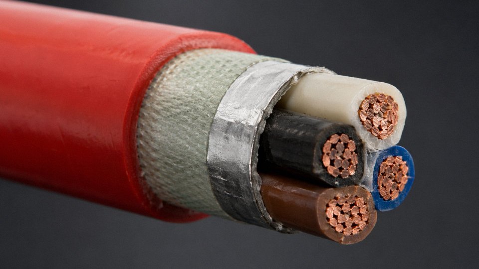
The core mechanism in a fire-survival cable is the mica tape layer wrapped directly around each conductor before any polymeric insulation is applied. Mica remains electrically insulating up to roughly 800°C — well above the char point of any thermoplastic insulation. When the outer layers burn away in a fire, the mica tape maintains circuit integrity, which is why IEC 60331 tests at 750–1000°C and requires that the cable continue to carry current throughout. This isn’t marketing language; it’s the specific physical property that keeps emergency lighting, fire pumps, and evacuation lifts running when everything around them is burning.
Combine that mica wrap with a low-smoke zero-halogen (LSZH) outer jacket — per IEC 60754 — and you get a cable that passes BS 6387 CWZ and IEC 60332-3-24 bundle fire tests. The “CWZ” designation is the hardest combination to achieve: C (flame at 950°C), W (flame plus water spray), Z (flame plus mechanical shock). For tunnels, data centers, and transit infrastructure, specifying anything less is usually non-compliant with local fire codes, and in practice the authority having jurisdiction will catch it during commissioning.
Flexible Trailing Cables for Cranes, Hoists, and Reels
A trailing cable on a port crane or cable reel goes through tens of thousands of flex cycles annually. Standard cables with Class 2 stranding will work-harden and crack conductors within months. Trailing cables use Class 5 or Class 6 stranding per IEC 60228 — the finest practical configurations — and the jacket compound matters as much as the conductor. Thermoplastic elastomer (TPE) handles cold-weather flexibility better, typically down to around -40°C depending on compound formulation, while polychloroprene (PCP, commonly called neoprene) offers better oil and ozone resistance for outdoor industrial applications. Minimum bend radius runs as tight as 5× OD in continuous dynamic service. Tensile load ratings vary considerably with cable diameter and construction, but dynamic tensile capacity is a parameter you need to confirm explicitly — don’t assume it from a static installation spec sheet.
Subsea and Submersible Cables
Offshore wind array cables operate under hydrostatic pressures that can reach 300 bar at depth, in an environment that will force water ingress through any gap in the cable construction given enough time. The defense-in-depth approach: swellable tapes and flooding compound provide longitudinal water blocking, a lead sheath acts as the primary moisture barrier, and double wire armor provides mechanical protection against installation stress and seabed abrasion. Voltage ratings for array cables typically run up to 33 kV. These aren’t off-the-shelf items; lead sheath extrusion and wire armoring require specific manufacturing capability that a standard building-wire plant doesn’t have.
Mining and ATEX/IECEx Zone Cables
Underground coal and gas mines impose two simultaneous demands that almost no other environment creates together: mechanical brutality and explosive atmosphere control. Anti-static jacketing limits surface resistivity to below 1×10⁹ Ω/square — this dissipates static charge rather than accumulating it, which matters enormously when methane concentrations can reach ignitable levels. Compound tracking resistance (CTI) must meet ≥600 V per IEC 60112. For Zone 1 and Zone 2 classified areas under ATEX or IECEx, the cable’s temperature class marking — T4, T5, or T6, representing maximum surface temperatures of 135°C, 100°C, and 85°C respectively — must match the ignition temperature of the gases present. Getting this wrong isn’t a cable failure. It’s potentially an ignition source.
Mica tape in fire-resistant cables maintains electrical insulation at temperatures up to approximately 800°C, enabling circuit integrity after polymeric insulation has burned away.True
Mica (muscovite and phlogopite types) is a naturally occurring mineral with documented thermal stability to 800–900°C. This property is the physical basis for IEC 60331 fire-survival cable construction and is consistent with materials science data, not a marketing claim.
Jinda’s specialty portfolio covers rubber-sheathed flexible cables for crane and hoist applications, fire-resistant LSZH cables meeting BS 6387 CWZ, and custom-engineered cables for mining and wind-energy projects — including subsea-capable constructions where lead sheath and wire armor are required. For procurement managers: these cables require longer lead times than standard product, sometimes 8–14 weeks depending on construction complexity and raw material availability, so building that into project timelines is not optional.
| Environment | Key Performance Requirement | Relevant Standard | Specification Trigger |
|---|---|---|---|
| Tunnel / transit fire survival | Circuit integrity at 750–1000°C | IEC 60331, BS 6387 CWZ | Emergency circuit, evacuation route |
| LSZH smoke/toxicity | Halogen acid gas ≤0.5% by mass | IEC 60754-1/2 | Public occupancy, confined space |
| Offshore / subsea | Longitudinal water block, 300 bar rated | IEC 60502-4 / project spec | Below-water installation |
| Underground mining | Surface resistivity <1×10⁹ Ω/sq, CTI ≥600 V | IEC 62932, IECEx | Zone 1/2 classified atmosphere |
| Crane / trailing | Class 5/6 stranding, bend radius ≤5× OD | IEC 60228 | Continuous dynamic flexing |
Side-by-Side Comparison: Selecting the Right Cable Type Using a 6-Factor Decision Matrix
Getting the cable type right before you commit to a bill of materials is one of those decisions that looks trivial until it isn’t. A misspecified jacket on an outdoor tray run, or a solid conductor on a flexing application, doesn’t fail on day one — it fails eighteen months in, during peak production, when replacement lead times are six weeks and the plant can’t wait.
The six factors below form a practical screen. Run any cable requirement through them in order and the right product family usually becomes obvious.
The Six Selection Factors
Operating voltage and current load sets the first hard boundary. Power cables occupy the MV and HV space; control and instrumentation cables rarely exceed 1 kV, and most run at 300/500 V or below. Data cables are functionally voltage-agnostic for transmission purposes but still carry safety-rated insulation. If your circuit is carrying load current — motors, transformers, bus feeds — you are in power cable territory, full stop.
Signal type and frequency bandwidth separates the next two families. A 4–20 mA analog loop and a hardwired discrete I/O signal need individually shielded pairs with overall shield coverage; 100 MHz+ Ethernet needs twisted-pair geometry controlled to tight impedance tolerances; single-mode fiber handles wavelengths in the 1310–1550 nm range entirely outside the copper domain. Mixing these up — running instrumentation signal cables in the same conduit as unshielded power conductors without adequate separation, for instance — is the single most common source of unexplained loop noise in new plant commissioning.
Environmental exposure covers temperature range, UV index, moisture ingress, chemical splash, and mechanical abuse. Standard PVC jacket is rated to roughly 70 °C and degrades visibly in direct UV within two to four years in high-irradiance climates. XLPE or HDPE outer sheaths handle continuous service up to 90 °C and resist UV significantly better. Petrochemical and offshore environments demand resistance to specific hydrocarbon families — check the ASTM or IEC chemical resistance data for the actual fluid, not just a generic “oil resistant” claim.
Fire performance requirements are non-negotiable once a cable enters an occupied building, a tunnel, a marine vessel, or any area where evacuation time matters. IEC 60332-1 is the baseline flame-spread test for individual cables; IEC 60332-3 covers bunched cable installations, which behave very differently in a fire. IEC 60331 adds circuit integrity under flame — critical for emergency power and fire-alarm circuits. BS 6387 Category CWZ is the most demanding combined test (flame, water spray, and mechanical shock simultaneously), required in many UK and Middle East infrastructure projects. Specialty fire-resistant cables with mica tape layers must meet these ratings regardless of installation method — you cannot substitute a standard XLPE cable even in a metal conduit and claim equivalent protection.
Installation method drives sheath selection and armor requirements more than almost any other factor. Direct burial needs an anti-termite PE outer sheath at minimum, plus steel wire or tape armor depending on soil conditions and traffic loading. Free-air tray installation in outdoor environments demands UV-stable compound. Underwater or subsea runs require lead sheathing or specialized water-blocking tape plus double steel wire armor. Conduit-pulled cables need adequate flexibility and a lubrication-compatible jacket — something that sounds obvious but gets ignored when the conduit has multiple bends.
Applicable project standards and regional certifications close the loop. IEC 60228 governs conductor classes; IEC 60502 covers extruded insulation for voltages up to 30 kV; UL 44 applies to thermosetting-insulated wires in North American projects. For ATEX/IECEx zones, the cable itself must be certified or the glands and termination hardware must compensate — the cable selection and the hazardous-area documentation are linked, not independent.
Decision Matrix: Four Cable Types Across Six Factors
| Selection Factor | Power Cable | Control & Instrumentation Cable | Communication & Data Cable | Specialty / High-Performance Cable |
|---|---|---|---|---|
| Voltage / current | Up to 500 kV; full load current | ≤1 kV; pilot/signal current only | Signal level; PoE up to ~90 W | Application-dependent; may span all tiers |
| Signal / bandwidth | Power frequency (50/60 Hz) | DC to ~20 kHz analog/digital | Up to 40 Gbps (copper); unlimited (fiber) | Matches host application |
| Environment | XLPE/PE for harsh; PVC for indoor | LSZH or PVC; screened for EMI zones | Plenum/LSZH for indoor; OSP gel-filled for outdoor | Mica tape (fire); EPR/HDPE (subsea/mining) |
| Fire performance | IEC 60332-1/-3 for bunched runs | IEC 60332-3 + LSZH where required | Plenum (UL 910) or LSZH (IEC 60332-3) | IEC 60331 / BS 6387 CWZ for FR/FP types |
| Installation method | All methods; armor grade varies | Tray/conduit preferred; avoid power cable bundling | Structured cabling pathways; OSP direct burial | Subsea armor; trailing cable flexing; tunnel |
| Standards / certs | IEC 60502, IEC 60228, UL 44 | IEC 60092, ISA-S82, ATEX for IS circuits | TIA-568, ISO/IEC 11801, IEC 60793/60794 | IEC 60331, BS 6387, IEC 60092-350, IEC 60794-4 |
Three Project Scenarios That Illustrate the Matrix in Practice
50 MW solar farm. This project needs at least three cable families running simultaneously. DC string cables from panel to inverter are typically 1.5 kV-rated single-core cables with UV-stabilized XLPE insulation and tinned copper conductors — the tin matters because sulfur compounds in some soil types corrode bare copper over a 25-year asset life. The AC collection network from inverters to the MV transformer uses standard 3.3 kV or 6.6 kV multicore armored power cable. The SCADA and meteorological monitoring circuits need individually screened instrumentation pairs, physically separated from the AC collection cabling by at least 200 mm in shared trays, or routed in dedicated conduit. Specifying a single cable type for all three circuits is a common early-stage design error that gets caught — expensively — during commissioning.
Petrochemical plant control room. The dominant requirement here is intrinsic safety (IS) on field instrument circuits and ATEX compliance throughout. Cables feeding IS circuits must be individually screened pairs with an overall screen, rated for the gas group in question, with LSZH jacket to limit toxic combustion products. Running these in the same trunking as non-IS circuits without certified segregation barriers invalidates the IS protection concept entirely. The outer jacket compound also needs to be compatible with whatever cleaning solvents or process fluids the cable is likely to contact — something specifiers in office environments routinely overlook.
Data center. Horizontal runs to the access layer are typically Cat 6A U/FTP or F/UTP depending on whether the facility uses a centralized or distributed EMI mitigation strategy; plenum-rated jacket is required in raised-floor or ceiling-plenum pathways under NFPA 70 in North American projects. The backbone between distribution frames and the core uses OS2 single-mode fiber — largely because the distance between MDA and HDA in any building over four floors exceeds the practical reach of OM4 multimode at 40 Gbps. Getting the backbone fiber wrong at installation stage means either re-pulling or accepting a performance ceiling well below what the active equipment can deliver.
Composite and Hybrid Cables
Some installations don’t fit cleanly into one family. Wind turbine tower wiring is the clearest example — the cable traveling from the nacelle down the tower needs to carry three-phase power from the generator, control signals for pitch and yaw systems, and sometimes fiber for real-time condition monitoring, all while surviving continuous torsional flexing as the nacelle rotates. Composite cables combining power cores, screened signal pairs, and tight-buffered fiber elements in a single outer sheath solve this elegantly. IEC 60794-4 governs the fiber elements within such cables; the power and signal portions must still meet their respective IEC standards. The benefit is reduced conduit count and simplified installation; the trade-off is that any single element failure means replacing the entire composite run, which is worth factoring into your maintenance cost model.
Common Specification Errors and Their Consequences
A few mistakes come up repeatedly across project types.
Under-specifying shielding on instrumentation runs is probably the most frequent. A cable with only an overall foil shield, installed in a tray that also carries variable-frequency drive output cables, will pick up switching noise that manifests as 4–20 mA signal jitter. Depending on the process, that jitter either triggers nuisance alarms or, worse, goes unnoticed and introduces measurement error. Individual pair shields with a drain wire, plus an overall braid, is the correct architecture for mixed-environment industrial instrumentation — not a luxury spec.
Selecting standard PVC jacket for outdoor UV-exposed tray installation is a slow-motion failure. PVC chalks and cracks after roughly two to four years of direct sun exposure at latitudes above about 30° — sooner in desert climates with high UV index. The cable doesn’t fail electrically right away; the jacket just stops providing mechanical and moisture protection, and the insulation follows. The fix costs several times what the jacket upgrade would have.
Choosing solid-conductor cable for a flexing application is the kind of error that shows up in flex life testing but not in a static installation inspection. Solid conductors work-harden under repeated bending and fracture; stranded Class 5 or Class 6 conductors per IEC 60228 are specified precisely for this reason. On mobile equipment and trailing cables, a solid conductor failure usually looks like an intermittent fault — maddening to trace, expensive to repair mid-shift.
Jinda's technical sales team provides free cable selection consultation backed by test reports, material certifications, and country-specific compliance documentationTrue
This is a stated service offering from Shandong Jinda Special Cable Group, consistent with the company's described after-sales and technical support infrastructure serving customers in over 50 countries.
If your project spans multiple cable families — which most industrial, infrastructure, and energy projects do — Jinda’s technical team can review your single-line diagram and cable schedule against the six factors above, confirm material and certification requirements for your target market, and provide formal test documentation. That kind of pre-order technical review catches specification mismatches before they become change orders.
Standards, Certifications, and Test Reports: What Buyers Must Demand from Any Cable Supplier
One of the most consistent mistakes I see in international procurement is buyers treating “certified cable” as a single checkbox. It isn’t. There are at least three distinct layers of standardization that need to line up before a cable shipment is genuinely compliant — and conflating them creates real exposure.
Product Standards, Installation Standards, and Performance Test Standards Are Not the Same Thing
Product standards define what a cable is: its construction, conductor class, insulation thickness, and voltage rating. IEC 60502 covers extruded solid dielectric power cables up to 30 kV; IEC 60228 classifies conductor flexibility classes; UL 44 governs thermoset-insulated wire for the North American market; BS 5467 covers armoured cables with thermosetting insulation for the UK and many Commonwealth markets. When you write a purchase specification, you reference these.
Installation standards — IEC 60364 and NEC Article 310 — govern how cable is applied in a building or plant. They’re the design engineer’s domain, not the factory’s. A cable can be fully IEC 60502-compliant and still be installed in violation of IEC 60364 if someone undersizes the conduit fill or ignores ambient temperature correction. Buyers occasionally try to hold manufacturers responsible for installation-standard compliance, which doesn’t work.
Performance test standards are a third category entirely. IEC 60332 series covers flame propagation — single vertical wire, bunched cables. IEC 60331 tests circuit integrity under fire conditions (relevant for emergency power and life-safety circuits). IEC 60754 measures halogen content in combustion gases; IEC 61034 measures smoke density. For any project with fire-safety requirements, these test reports need to be on the table before you accept a cable order. Specify which parts of IEC 60332 apply — Part 1, Part 3-22, Part 3-24 have different pass criteria and are not interchangeable.
The Five Documents That Should Be Non-Negotiable
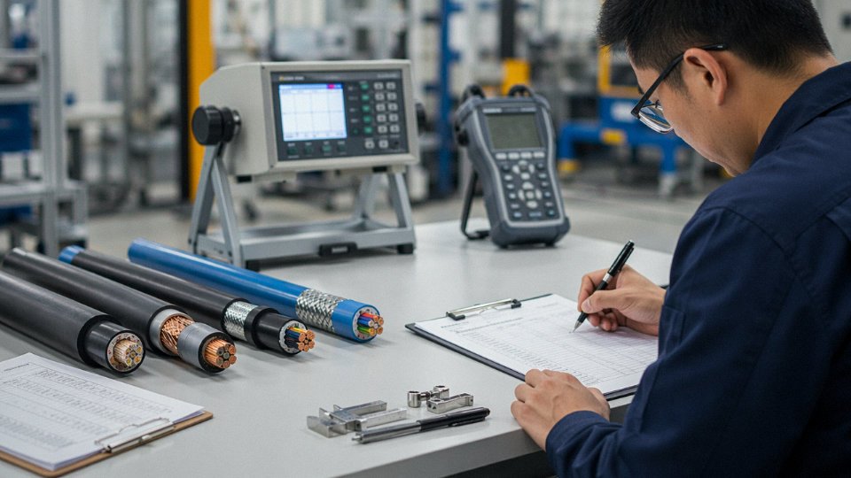
Routine test reports cover conductor DC resistance, voltage withstand (typically 3.5 kV or 7 kV AC for medium-voltage grades), and insulation resistance, all per IEC 60502-1 Clause 16. Every manufactured drum should carry one. Type test reports — bending, tensile strength, thermal aging, water penetration — are performed once per cable design and are valid until there’s a design change; ask for the date and check whether the tested construction matches exactly what you’re ordering. Construction changes get quietly made in factories more often than they should.
Third-party certification marks depend heavily on destination. CE for the EU, UL listing for North America, CCC (China Compulsory Certification) for domestic Chinese use, KEMA or BASEC for certain utility and building applications, SASO for Saudi Arabia, INMETRO for Brazil. Getting the wrong mark — or a photocopy of someone else’s certificate — is a surprisingly common problem in spot-buy procurement.
Material certificates matter. Conductor purity should meet ASTM B3 minimums (99.9% copper), and you should ask for the mill certificate, not just the cable factory’s word. Insulation compound certificates confirm the actual compound grade used rather than what was specified on the drawing.
Factory audit reports from SGS, Intertek, or TÜV close the loop. A certificate on paper is one thing; a recent third-party audit of the actual production facility is something else.
Industry estimates suggest 10–25% of cables in developing-market infrastructure projects fail to meet their stated specifications.True
Multiple TIC-body and industry association surveys (IEC, Europacable, and regional electrical safety bodies) have documented high rates of non-compliant cable in emerging markets, with figures in this range cited across multiple independent studies.
That failure range translates directly into fire risk, insurance voiding, and project delays when local inspectors test on arrival. On a large project, one non-compliant drum found during incoming inspection can hold up commissioning for weeks while the dispute is resolved.
Reading a Drum Test Report Correctly
When a test report arrives with a delivery, check three things before filing it. First, the measured conductor cross-section should fall within –0/+1% of nominal per IEC 60228 — a 95 mm² conductor reading 93.5 mm² is out of tolerance and likely undersized. Second, insulation thickness needs to meet the minimum average value in the relevant standard; the minimum point measurement (usually 85–90% of nominal depending on standard and voltage class) is a separate requirement. Third, the drum length on the test report should match the delivery note within roughly 0.5%. Discrepancies beyond that sometimes indicate repackaged or substituted drums.
CCC, CE, and Export Documentation in Practice
CCC certification is mandatory for cables supplied into the Chinese domestic market across roughly 14 cable product categories, including low-voltage wires and cables for buildings. The process involves factory inspection by a CNCA-authorized body and product testing — it’s not a self-declaration. CE, by contrast, is a Declaration of Conformity that the manufacturer issues based on meeting the applicable directive (typically the Low Voltage Directive 2014/35/EU or the Construction Products Regulation depending on application). The manufacturer carries responsibility for that declaration, which is why having a supplier with an established, auditable quality system behind it matters.
Jinda maintains an ISO 9001-certified quality management system across its production operations, with an in-house high-voltage test laboratory capable of testing up to 110 kV — which covers routine and type testing for medium-voltage and HV cable grades without relying on third-party lab scheduling. Spark test equipment runs on all production lines as a 100% screen for insulation defects. A dedicated export compliance team manages certification documentation for over 50 destination markets, which in practice means the CCC dossier, CE declarations, SASO applications, and destination-specific material certificates are managed in parallel rather than scrambled together at the end of a project.
The short version for any procurement manager: ask for all five document types upfront, verify the marks against the issuing body’s online registry where one exists (UL’s is public; CCC’s is on the CNCA website), and check the drum report numbers before material is accepted at site. It adds maybe two hours of administrative work per order. The cost of not doing it can be a condemned installation.
Frequently Asked Questions About Cable Types, Specifications, and Global Procurement
What is the difference between a cable and a wire?
A wire is a single conductor — either solid or stranded — with or without a basic insulation layer over it. A cable is an assembly: two or more insulated conductors brought together under a common sheath, armor, or jacket, sometimes with fillers and bedding layers in between. Both IEC and NEC draw this line explicitly, and it matters practically because they are tested differently, routed differently, and in many jurisdictions require different conduit fill calculations. On the plant floor, the confusion usually causes problems when someone installs single-conductor building wire in a tray application that calls for a rated multi-core cable — fire resistance, mechanical protection, and ground fault behavior are simply not equivalent.
Can I use a power cable for instrumentation signals?
Technically you won’t blow anything up. The voltage levels are compatible. But power cables have no individual pair shielding, no controlled twist pitch, and no defined characteristic impedance — all three of which matter the moment you’re running 4–20 mA loops or HART signals through an electrically noisy environment near VFD panels, large motors, or switch-mode power supplies. The result is common-mode noise pickup and capacitive crosstalk that shifts your loop current by enough to produce false readings — a flow transmitter reading 4 mA high sounds minor until it trips a reactor or masks a low-flow alarm. In practice, even a short parallel run of 10–15 m between a power cable and an unshielded signal pair in the same tray can degrade loop accuracy measurably. Spend the small cost difference on a proper instrumentation cable; the commissioning hours you save are worth it.
What does XLPE stand for, and why is it preferred over PVC above 6 kV?
XLPE is cross-linked polyethylene. The cross-linking process — done either by peroxide, silane, or electron beam methods — forms covalent bonds between adjacent polymer chains rather than the weaker van der Waals interactions in standard thermoplastic PE or PVC. The practical payoff: continuous operating temperature rises from PVC’s 70°C ceiling to 90°C (105°C for some specialty grades), dielectric strength increases substantially, and the insulation retains dimensional stability under thermal cycling. PVC at medium and high voltage also contains plasticizers that migrate out over time, leaving the compound brittle and prone to micro-cracking at joints — a failure mode that typically shows up 8–12 years into service, usually at the worst possible moment. Above 6 kV, specifying PVC insulation is a short-term procurement saving with a long-term maintenance liability attached.
XLPE-insulated cables maintain dielectric integrity at continuous operating temperatures up to 90°C, compared to 70°C for standard PVC, as defined under IEC 60502 and IEC 60840.True
This temperature rating difference is established in IEC conductor and insulation standards and is consistently applied across major international cable specifications.
How do I calculate cable quantity to account for waste and bends?
Measure your route centerline, then add 10–15% for horizontal bends, elevation changes, and tray routing geometry. Allow 1–2 m per termination end for working length at the panel or equipment. For direct-burial or submarine runs, add another 2–5% to account for burial depth undulations and bottom contour — a cable pulled tight across a trench that settles will crack at the stress points. Drum lengths need to match your route segments; a 500 m drum cut to two 220 m runs wastes roughly 60 m unless you can use the offcut elsewhere on the project.
What minimum order quantities should I expect for export cable orders?
For standard LV power cable and Cat 6 LAN cable, MOQs typically start somewhere in the 1,000–5,000 m range per line item, depending on conductor cross-section and whether the product is in active production. Custom builds — non-standard jacket colors, unique conductor combinations, CE plus one additional regional certification on the same drum — generally require 5,000–20,000 m because of the production setup, certification sampling, and drum labeling overhead. Jinda accommodates project-split orders across multiple drum sizes, which is useful when your cable schedule has 15 different part numbers and only three of them hit the standard MOQ on their own.
What is the realistic shelf life of a cable drum in storage?
Most manufacturers rate covered, dry storage at –20°C to +50°C with sealed drum ends at roughly two years. UV-stabilized HDPE-jacketed cables handle outdoor staging yards reasonably well within that window. PVC-jacketed cable is a different story — plasticizer loss and surface oxidation under UV exposure can begin causing surface cracking inside 12 months of outdoor storage, especially in high-UV or high-temperature climates. If your project is phased and cables will sit on-site for an extended period, specify UV-resistant outer jackets and store drums end-on-end on wooden dunnage, off the ground, under cover. Inspecting drum ends and doing a bend test on the outer wrap before pulling is a basic pre-installation check that catches storage damage before it becomes a failed cable in a conduit.
How does Jinda support buyers after the order ships?
Jinda’s international technical support team handles material test certificates, third-party lab reports, HS code documentation, and country-specific certification letters as part of standard export documentation. If something goes wrong on-site — a splice failure, a drumming discrepancy, an unexpected test result — the after-sales process includes failure analysis reports, drum reconciliation (tracking which production batch went to which drum), and replacement logistics coordination. For large infrastructure or EPC projects where cable delivery phasing matters, that traceability layer is not a nice-to-have; it’s what makes a warranty claim actually resolvable.
Why Jinda’s Five-Base Manufacturing Network Guarantees Supply Reliability for Global Cable Projects
Large EPC projects fail on cable supply more often than most project managers want to admit. A single-factory supplier running at 85% capacity hits a wire-drawing bottleneck in week three of your delivery window, and suddenly a substation commissioning date slips by six weeks. That scenario is not hypothetical — it’s a structural risk in how most mid-tier cable manufacturers are built. Jinda’s five-production-base model exists specifically to eliminate that single point of failure.
Geographic Distribution as a Supply Risk Strategy
Spreading production across Shandong province and broader China is not just about having more floor space. Each base runs a partially independent supply chain: raw copper and aluminum rod sourcing, conductor drawing, and finished goods logistics are managed at the base level, so a regional logistics disruption, a port closure, or a raw material allocation issue at one facility doesn’t freeze the entire production schedule. For a large infrastructure project ordering LV switchboard feeders, MV underground distribution cables, and armored control cables simultaneously — the kind of mixed bill of materials a typical substation or industrial park generates — parallel production across bases means all three categories move through the shop concurrently rather than queuing behind each other on a single extrusion line.
What 470,000 m² Actually Looks Like
That footprint is not warehouse space dressed up as manufacturing. The allocation runs roughly as follows: raw material storage and copper/aluminum rod inventory holds a meaningful buffer — typically four to eight weeks of production stock depending on market conditions — which matters when LME copper swings hard and spot purchasing becomes expensive. Wire drawing shops pull rod down to the conductor sizes demanded by IEC 60228 Class 1 through Class 5 requirements. Stranding and cabling lines then lay up conductors for everything from 1.5 mm² control cores to large-section 630 mm² power conductors. Insulation extrusion lines run XLPE and PVC compounds, with inline spark testing at voltages matched to the cable’s rated voltage class — not a sampling check, a 100% pass-through. Armoring and sheathing lines apply steel wire, steel tape, or aluminum wire armor depending on the specification, followed by final sheath extrusion. Drum winding and finished goods storage close the loop, with each drum labeled and traceable to its production batch and test record.
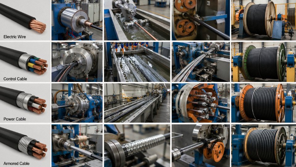
Inline quality checkpoints at each stage — conductor resistance verification, insulation thickness measurement, spark test records — mean defects are caught at the process step where they occur, not at final inspection after you’ve already added four more production layers on top of a bad core.
Vertical Integration Cuts Engineering Review Time
Purely trading-based suppliers route your non-standard specification to a third-party factory that may or may not have done that construction before. Jinda’s internal R&D team handles custom cable designs directly: a fire-resistant, screened, oil-resistant trailing cable for an offshore platform application, for instance, gets an engineering review and a prototype cable schedule within roughly one to two weeks rather than the four to six weeks typical when an intermediary is relaying information back and forth to a factory they don’t fully control.
Jinda's in-house R&D and testing capability reduces custom cable engineering review cycles compared to trading-based suppliers.True
Vertically integrated manufacturers with internal engineering teams can iterate on cable construction designs without routing specifications through third-party factories, which typically shortens review-to-approval timelines.
The workforce backing this — over 1,000 employees including cable engineers, process technicians, and quality inspectors trained against IEC test method competencies — means test results are interpreted by people who understand what the numbers mean, not just whether the value printed on the report clears a threshold.
Lead Times Procurement Managers Can Plan Against
Standard LV power cables: 15–30 days ex-works, depending on conductor size and order volume. MV cables (typically 6 kV through 35 kV): 30–45 days, longer for larger cross-sections or non-standard insulation thickness. Specialty and custom cables — mining trailing, fire-resistant instrumentation, submarine — run 45–60 days, and honestly, if a supplier quotes you less than that for a genuinely engineered product, ask to see the production schedule. On the freight side: sea transit to the Middle East runs roughly 18–25 days from a Shandong port; Southeast Asia 7–14 days; Europe 28–35 days depending on routing. Those windows let you build a realistic procurement timeline rather than guessing.
Jinda has been doing this since 1987, supplying projects across more than 50 countries. If you’re a procurement manager, EPC contractor, or project developer with a cable schedule or bill of materials in hand, submit it for a no-obligation technical review and competitive quotation. Bring the actual specification — conductor class, voltage rating, installation method, any local approval requirement — and get a response from engineers, not a sales script.