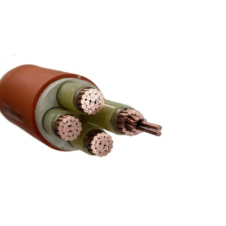
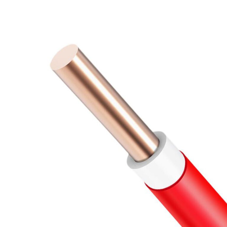
Specifying the wrong cable type doesn’t just slow a project down — it can trigger insulation breakdown under load, nuisance tripping across an entire distribution board, or a fiber link that saturates at peak shift and forces a production halt. Procurement teams that treat “cable” as a single commodity category consistently pay for it: rework, expedited replacement orders, and in some cases, requalification of an entire panel installation. The fix isn’t complicated, but it requires understanding that the four fundamental cable categories exist because the physics of what each one carries — power, signals, data, or control — demands genuinely different material choices, shielding geometry, and conductor sizing logic.
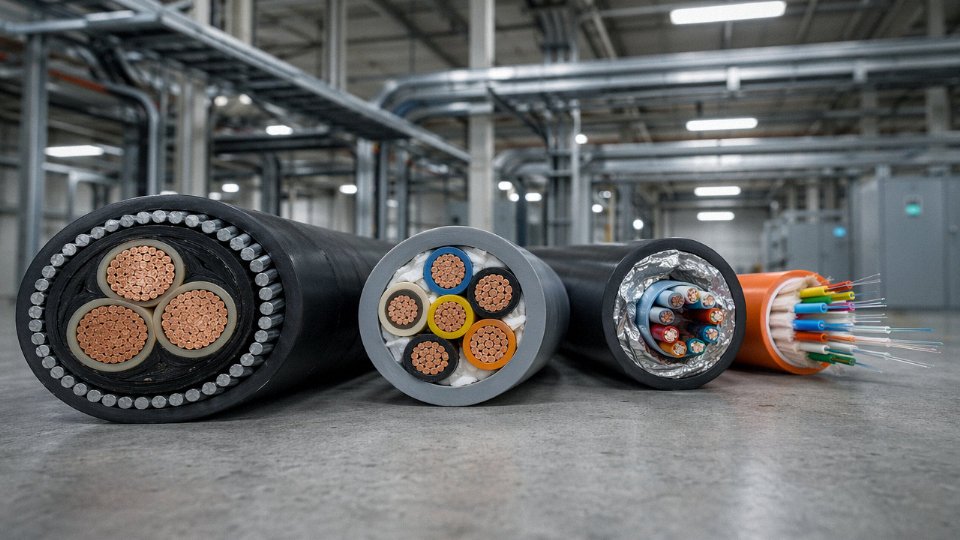
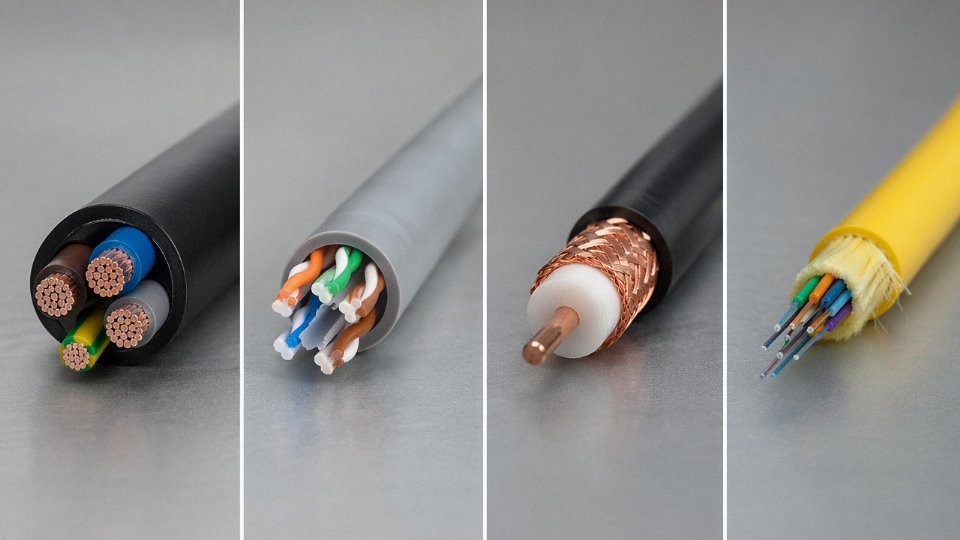
The four types of cables are power cables, control cables, instrumentation cables, and communication (including fiber optic) cables. Power cables carry electrical energy at voltages from below 1 kV up to 220 kV and beyond. Control cables transmit switching and command signals at low voltages, typically 300–600 V. Instrumentation cables handle small analog or digital signals from sensors and transmitters. Communication and fiber optic cables move data, with modern single-mode fiber capable of exceeding 100 Gbps over 80 km without regeneration.
What makes this more interesting — and more consequential for anyone buying or specifying cable at scale — is how much overlap exists in appearance but not in performance. A control cable and an instrumentation cable can look nearly identical on a reel, same outer diameter, same color sheath, even similar part numbers from a mid-tier distributor. Put them in the wrong application and you may not see the failure for weeks, until a 4–20 mA signal starts drifting under electromagnetic interference from a nearby VFD. The global cable market was sitting around USD 225 billion in 2023 and is tracking toward USD 300 billion by 2030 — that growth is being driven by electrification, data infrastructure, and industrial automation, all of which demand tighter, not looser, discipline around cable selection.
Power Cables: Construction Layers, Voltage Classes, and Conductor Material Trade-offs
Power cables move more tonnage through factories, substations, and buried infrastructure than any other cable category combined. Getting the construction wrong doesn’t just cause a nuisance fault — it causes fires, prolonged outages, and insurance disputes. So the anatomy matters.
How a Power Cable Is Actually Built
A medium-voltage power cable is essentially a stack of functional layers, each solving a specific problem. Starting at the center: the conductor, which is either stranded copper or aluminum in circular or shaped-sector form. Over that sits a semiconducting conductor screen — usually 0.5–1 mm of extruded carbon-black compound — whose job is to smooth out the electric field and prevent partial discharge at strand gaps. Without it, you’d see premature insulation degradation at any voltage above roughly 6 kV.
The insulation layer is where most of the engineering tradeoffs live. XLPE (cross-linked polyethylene) dominates medium- and high-voltage construction because it handles 90°C continuous conductor temperature and survives short-circuit events up to around 250°C without melting. Wall thickness here ranges from about 2.5 mm at 6 kV up to 25–27 mm at 220 kV, depending on design field stress. PVC is still common at low voltage (up to 1 kV) and in small cross-sections — say, 1.5 to 16 mm² — because it’s cheaper, more flexible, and easier to terminate in tight enclosures. The trade-off is that PVC is limited to 70°C continuous, which directly cuts your ampacity in warm ambient conditions.
Above the insulation screen (a second semiconducting layer, mirror of the first) comes the metallic sheath — copper tape, aluminum foil-laminate, or lead for high-voltage submarine cables — providing both earth fault return path and moisture ingress protection. Armoring follows for mechanical protection: steel wire armour (SWA) is standard for most buried or cable-tray applications, while aluminum wire armour (AWA) is used on single-core cables where steel would cause unacceptable eddy-current heating. The outer jacket, typically HDPE or PVC, is the last line of defense against UV, chemical attack, and abrasion.
Voltage Classes and Applicable Standards
IEC 60502 covers production and test requirements from 1 kV through 30 kV. IEC 60840 picks up from 30 kV to 150 kV, with IEC 62067 handling extra-high-voltage above 150 kV. These aren’t just bureaucratic distinctions — each standard specifies insulation eccentricity limits, partial discharge test levels, and impulse withstand voltages that directly determine whether a cable survives a switching transient in service.
Low-voltage cables (up to 1 kV) are workhorse distribution cables: factory floors, commercial buildings, infrastructure. Medium-voltage (1–35 kV) handles primary distribution loops, industrial plant feeds, wind turbine tower cables. High-voltage (35–220 kV) is transmission — grid interconnects, large substation feeders, offshore wind export cables. Above 220 kV you’re typically in HVDC or EHV AC territory, where cable joints become genuinely difficult and jointing crew qualifications matter as much as the cable itself.
Copper vs. Aluminum: The Real Procurement Decision
Copper conductivity runs around 58 MS/m; aluminum sits near 35 MS/m. That gap means an aluminum conductor needs roughly 1.6× the cross-section to carry the same current — so a 240 mm² aluminum cable roughly equals a 150 mm² copper cable in ampacity, give or take derating factors.
Aluminum conductors are typically 30–40% cheaper than copper conductors on a per-unit-weight basisTrue
Aluminum commodity pricing is substantially lower than copper; the exact differential fluctuates with LME copper and aluminum spot prices but the 30–40% range by weight is a consistent industry approximation, though the installed cost gap narrows when you factor in larger conduit sizes and specialist compression joints needed for aluminum.
Aluminum’s weight advantage is real — roughly one-third the density of copper — which matters on long overhead runs and large submarine cable reels. The jointing complexity, though, is a legitimate concern. Aluminum oxidizes quickly; improper jointing compound application or use of standard copper lugs on aluminum conductors leads to resistance creep at the joint, heat, and eventual failure. In plants I’ve seen, the cost savings from switching to aluminum got eaten up twice over by a single failed joint causing a production shutdown. Use the right bi-metal lugs, apply inhibitor compound, and torque to spec — or budget for copper and simplify your maintenance life.
Cross-Sections, Ampacity, and Derating in Real Installations
Power cables span 1.5 mm² at the small end (lighting circuits, instrumentation feeds) up to 2500 mm² for large generator and transformer connections. Ampacity published in IEC 60364-5-52 or manufacturer data sheets assumes specific baseline conditions — typically 20–30°C ambient, cables installed in free air or a defined burial depth. Group more than three cables together in a tray and you’re typically derating by 15–40% depending on configuration. Ambient temperature in a rooftop cable tray in summer can easily hit 50–55°C in southern climates, pushing derating factors further.
Direct burial requires armored construction (SWA or AWA) plus appropriate burial depth — generally 600–900 mm depending on voltage class and local regulations. Cable duct installations run slightly lower ampacity than direct burial due to reduced heat dissipation, though they simplify future replacement. Submarine cables add lead sheath and often a second armour layer for abrasion resistance on rocky seabeds. Overhead bundled conductors are a different sub-category with their own mechanical tension and sag calculations.
Getting the installation method locked in before specifying the cable isn’t optional — it’s what determines whether the cable you buy actually delivers the current your load demands without running hot.
Control Cables: Multi-Core Configurations, Shielding Options, and Industrial Automation Roles
Control cables occupy a different functional space than power cables, and conflating the two is one of the more common — and quietly expensive — mistakes in panel wiring and field installation. A power cable moves energy. A control cable moves intent: a 24 V DC signal telling a valve to open, a feedback line confirming a contactor has closed, a 4–20 mA loop reporting temperature from a thermocouple transmitter. The currents are tiny, often a few milliamps. The consequences of getting the cable wrong, though, are not.
IEC 60227 defines the typical voltage ratings for control cables at 300/500 V or 450/750 V — well below what a medium-voltage power cable sees — and that lower rating is not just a cost-reduction move. It reflects the actual circuit environment these cables live in: instrument loops, PLC I/O wiring, relay logic panels, and actuator command circuits.
Core Count and How It Maps to Control Points
The multi-core configurations available in control cable — commonly 4, 7, 12, 19, 27, 37, or 48 cores, though some manufacturers go higher — exist because real control panels need to route a lot of discrete signals through a single conduit or cable tray run. A 19-core cable to a remote junction box might carry start/stop commands, motor-run feedback, fault status, and a handful of analog signals simultaneously. Pulling 19 individual single-core cables instead wastes tray space, complicates installation labor, and makes fault-tracing a misery six months later during a shutdown.
Core count selection should follow the control point inventory from your I/O schedule, with typically 15–20% spare cores added for future modifications. Plants that skip that spare allowance tend to regret it at the first process expansion.
Shielding: Matching the Shield Type to the Noise Environment
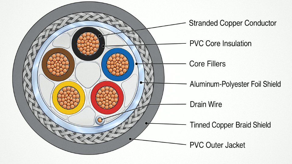
This is where control cable selection gets genuinely nuanced. In a clean relay logic panel with no variable-frequency drives nearby, an unshielded multi-core cable is often perfectly adequate. But install the same cable in a tray running parallel to VFD output conductors, and you will induce noise that causes spurious PLC inputs, ghost faults, and — in worst cases — unintended actuator trips.
The main shielding options and their practical roles:
| Shield Type | Best Use Case | Limitation |
|---|---|---|
| Overall foil (Al/polyester) | General EMI rejection, cost-effective | Foil tears easily during installation |
| Overall braid (tinned copper) | High-flex applications, better drain | Heavier, higher cost |
| Individual pair foil | Multi-signal cables where crosstalk between pairs matters | Adds significant diameter |
| Foil + braid combination | VFD-dense environments, serious industrial automation | Most expensive, justified in harsh EMI |
In practice, plants running a lot of VFD-controlled motors — food processing lines, HVAC plants, petrochemical compressor stations — should default to foil-plus-braid shielded control cables for any instrumentation wiring within a few meters of drive panels. The cost delta is real but small against the diagnostic labor you will spend chasing ghost faults.
LSZH vs. PVC: Where the Jacket Material Actually Matters
Standard PVC-insulated control cables are fine for most open industrial environments. The calculus changes inside tunnels, offshore platform cable decks, data center raised floors, or any space with limited ventilation and occupancy during a fire event. PVC burns and releases hydrogen chloride — corrosive, toxic, and damaging to electronics. LSZH (Low Smoke Zero Halogen) compounds per IEC 60332 dramatically reduce both smoke opacity and halogen acid gas emission.
Offshore and tunnel specifications almost always mandate LSZH. Specifying standard PVC in those environments is not just a code violation; a fire in a confined cable deck can take out instrumentation that survives the initial event but corrodes over weeks from HCl exposure.
Conductor Class and Installation Type
IEC 60228 conductor classes matter here more than most engineers acknowledge. Class 2 (stranded, fixed installation) works well in cable trays and conduit. Class 5 or 6 (finely stranded, flexible) is necessary for drag chains on CNC axes, robotic arm wiring, or any application where the cable flexes repeatedly — sometimes millions of cycles. Using a Class 2 cable in a drag chain will cause conductor fatigue failures within months, usually at the termination point.
Control cables appear across virtually every industrial sector: switchgear panels in power plants, valve actuator wiring in petrochemical units, building management system field buses, and CNC machine tool control cabinets where dozens of control points feed axes, spindles, and safety interlocks through a single neat cable bundle. Getting the specification right at the procurement stage — core count, shield type, jacket material, conductor class — determines whether the installation runs quietly for a decade or generates recurring fault calls.
Control cables rated 300/500 V or 450/750 V per IEC 60227 are not suitable for carrying bulk power loads and must not be substituted for power cables even in low-voltage circuitsTrue
IEC 60227 control cable construction — conductor cross-section, insulation wall thickness, and thermal rating — is optimized for low-current signal circuits. Using them as power conductors risks overheating, insulation breakdown, and fire risk because the cable is not rated for sustained load current.
Communication and Data Cables: From Twisted-Pair Ethernet to Fiber Optic Infrastructure
At the physics level, communication cables split into two fundamentally different families: copper cables that move electrons, and fiber optic cables that move photons. That distinction drives everything downstream — bandwidth ceiling, distance limitation, immunity to electromagnetic interference, and installed cost per meter. Choosing the wrong branch doesn’t just limit performance; it can mean ripping out infrastructure two years after commissioning when the network outgrows it.
Twisted-Pair Ethernet and Structured Copper Cabling
Twisted-pair cable works by exploiting differential signaling. Each pair twists at a specific rate so that external noise induces roughly equal interference on both conductors, which then cancels at the receiver. The tighter the twist and the better the pair-to-pair isolation, the higher the usable frequency — and that’s what separates the categories.
Cat5e handles up to 1 Gbps over 100 m and remains common in older commercial buildings. Cat6 hits the same 1 Gbps / 100 m but with tighter manufacturing tolerances and a plastic spline separating the pairs, which meaningfully cuts alien crosstalk. Cat6A steps up to 10 Gbps at 100 m — the current workhorse for new data center horizontal runs — and almost always ships as F/FTP (foil-shielded individual pairs plus an overall braid) or S/FTP, which adds a braided outer screen over the foil pairs. That shielding matters in industrial environments near VFDs or switch gear; unshielded U/UTP Cat6A in those spaces produces enough noise to drop links repeatedly. Cat7 and Cat8 push to 25–40 Gbps but only at 30 m or less, which makes them practical inside a server rack or between top-of-rack switches rather than in typical horizontal runs.
One thing worth knowing in procurement: Cat6A cables are noticeably thicker and stiffer than Cat6, especially in S/FTP variants. Cable tray fill calculations change. Bend radius matters more. A plant-floor or data center designer who specs Cat6A without accounting for tray capacity sometimes ends up with a cable management problem that wasn’t in the original budget.
Coaxial cable — inner conductor, solid or foam dielectric, foil or braided outer conductor, PVC or LSZH jacket — has lost most backbone network roles to fiber, but it hasn’t disappeared. CCTV analog distribution, CATV/satellite feeder runs, and RF antenna systems still rely on it. The characteristic impedance (typically 75 Ω for video, 50 Ω for RF/data) has to match the termination impedance precisely, or you get reflections that degrade signal quality. In practice, coax is often the right answer for a CCTV system covering a factory yard, especially where the installers are familiar with BNC terminations and the run lengths are under 300 m for standard RG-6.
Single-Mode and Multimode Fiber Optic Cables
Single-mode fiber (OS1 for indoor/conduit, OS2 for direct-burial or low-attenuation applications) uses a 9/125 µm core — narrow enough to allow only one propagation mode, which eliminates modal dispersion and enables transmission at 100 Gbps and beyond over distances exceeding 80 km without regeneration. That’s the basis for metropolitan and long-haul networks, and increasingly for hyperscale campus spine runs.
Multimode fiber uses a larger core — 50 µm for OM3 through OM5, 62.5 µm for the older OM1/OM2 — and supports multiple light modes simultaneously. Modal dispersion limits both bandwidth and distance, but for intra-building or campus runs under roughly 300–400 m at 100 Gbps, OM4 or OM5 is less expensive to terminate and easier to work with than single-mode. OM5 specifically supports wideband multimode (WBMMF), which allows short-wavelength division multiplexing and is aimed at pushing 400 Gbps over existing 50 µm infrastructure.
Single-mode fiber can transmit data at speeds exceeding 100 Gbps over distances greater than 80 km without signal regeneration.True
This is consistent with current dense wavelength division multiplexing (DWDM) deployments on OS2 single-mode fiber, where 100 Gbps per wavelength channel and multi-span links exceeding 80 km between amplifier/regenerator sites are standard practice in telecommunications infrastructure.
Connector choice is straightforward in most cases: SC connectors for older installations and patch panels where pull-out force is a concern; LC for high-density panels because the smaller form factor roughly doubles port density; MTP/MPO for trunk cables in 40/100/400 Gbps parallel optics applications where you’re terminating 8, 12, or 24 fibers at once. Getting the polish type right — UPC versus APC — matters more than people expect. Mixing APC (angled) and UPC connectors causes insertion loss spikes that can drop a link or degrade bit error rates without producing an obvious fault.
Armored Fiber for Industrial and Direct-Burial Use
Industrial deployments add mechanical risk that standard fiber construction doesn’t tolerate. Armored fiber — typically a steel or corrugated aluminum interlocked armor layer between the cable core and the outer jacket — handles rodent damage, accidental impact, and the tensile loads that come with direct burial. The internal construction matters too. Gel-filled loose-tube designs flood each buffer tube with thixotropic gel that blocks longitudinal water migration; this is the standard choice for direct-burial and outdoor aerial runs. Tight-buffered cables, where each fiber has a solid polymer layer directly on the coating, are easier to handle inside buildings and terminate without special cleaning procedures, but they aren’t appropriate for wet environments without additional protection.
Demand across the entire fiber segment has been growing at roughly 8% per year from 2020 through 2023, driven by 5G fronthaul and midhaul networks, hyperscale data center expansions, and smart grid communication backbones that need reliable high-bandwidth links between substations. That growth rate shows no sign of plateauing — if anything, the volume of fiber being pulled into industrial facilities is accelerating as OT/IT convergence pushes Ethernet deeper into the plant floor, displacing legacy fieldbus copper in new installations.
Instrumentation Cables: Signal Integrity, Noise Rejection, and Process Industry Requirements
Instrumentation cables are the category most engineers underestimate until something goes wrong. They look similar to control cables on a spool. The voltage ratings are modest — typically 300 V rms. But the signals they carry are fragile in a way that general control circuits never are.
A 4–20 mA current loop riding on a two-core cable shares a panel with VFD output cables, motor starters, and bus bars. The noise environment is brutal. And the instrument at the far end is trying to resolve a process temperature to within 0.1 °C, or a flow rate to within 0.25% of span. That requires a completely different design philosophy from a cable that just needs to switch a relay or carry a 24 V digital signal.
What “Low-Level Analog” Actually Means in Practice
The signal types instrumentation cables carry set the performance floor. A Type K thermocouple at 200 °C produces roughly 8 mV. An RTD in a 4-wire Pt100 circuit might present a resistance change of 0.4 Ω for a 1 °C shift. A 4–20 mA loop scaled to a 0–100 bar pressure transmitter carries only 16 mA of working range. Noise pickup in the tens of microvolts or milliohm-range ground potential differences can translate directly into visible process errors — false high-temperature alarms, flow readings that hunt, pressure readings that drift with cable routing changes.
This is why instrumentation cables are built around individual pair or triad shielding, not just an overall braid. Each pair or triad gets its own foil shield and drain wire, so a thermocouple circuit and a millivolt signal circuit running in the same multicore cable don’t cross-couple into each other. The overall shield handles external field interference. The drain wire is the critical element many installers mishandle: it must be grounded at one end only, at the instrument room or marshalling cabinet end, never at both ends. Grounding both ends creates a ground loop that can inject 50 or 60 Hz noise directly onto the signal — sometimes enough to saturate a DCS input card.
Shield continuity is not something to verify once during commissioning and forget. Any junction box where pairs are terminated is a potential break point. In my experience, roughly 30–40% of unexplained analog signal noise issues on older plants trace back to a corroded or disconnected drain wire connection somewhere in the field run, not to the instrument or the card.
Thermocouple Extension and Compensating Cables
This is a specialized subset that deserves its own procurement attention. Standard copper conductors cannot be used between a thermocouple junction and the transmitter head without introducing parasitic EMF errors. The conductors must be made from alloys matched to the thermocouple type — or at minimum from compensating alloys with equivalent thermoelectric behavior over the ambient temperature range of the cable run.
IEC 60584 defines the alloy pairs for each thermocouple type: Type K extension cable uses Chromel/Alumel alloys, Type J uses iron/copper-nickel, Type T uses copper/copper-nickel, and so on. Getting this wrong is common in facilities where a maintenance team replaces a damaged cable run with whatever copper cable is in the storeroom. The error may be small at ambient temperatures close to 20 °C and invisible to a basic loop check, but it grows with ambient temperature swings — a real problem in outdoor runs or near furnace walls where ambient can reach 60–80 °C.
Using standard copper cable instead of the correct thermocouple extension cable will introduce thermoelectric EMF errors that increase with ambient temperature variation.True
Any conductor junction at a temperature different from 0 °C where dissimilar metals meet will generate a parasitic Seebeck voltage. Copper junctions substituted for the matched alloy pairs in thermocouple extension cables produce this error, which grows proportionally with the temperature differential along the cable run.
Construction Parameters Engineers Must Actually Specify
Pair count runs from single-pair up to 50+ pairs in a single cable, and the choice affects how you route, how many junction boxes you need, and how you manage spare capacity. For DCS marshalling in a large refinery, 12- to 24-pair cables are typical; individual pairs are more common for critical loops where you want physical isolation.
Capacitance per unit length matters more than most procurement specs acknowledge. Target below 100 pF/m for analog loops, and significantly lower — often below 50 pF/m — for HART-enabled loops or digital fieldbus variants like Foundation Fieldbus H1 or Profibus PA, where characteristic impedance and propagation delay become real constraints. High capacitance on a HART loop degrades communication reliability at extended cable lengths, usually noticeable beyond 1,000 m depending on the number of devices on the segment.
For oil and gas facilities, the cable jacket and insulation system have to meet fire performance standards that general-purpose instrumentation cables don’t. IEC 60331 fire resistance, BS 5308 Part 1 (thermoplastic) or Part 2 (elastomeric), and API RP 540 all appear in offshore topside and onshore plant specifications. The BS 5308 designation is particularly common in projects designed to UK or international upstream standards — if a specification calls for BS 5308 Part 1 Type 1 or Type 2, that defines the specific screen construction and jacket compound, not just general intent.
Pharmaceutical clean-room instrumentation adds a different set of constraints: low outgassing, LSZH jacket compounds compatible with the room’s HVAC validation, and often a requirement to document material traceability for FDA or GMP audit purposes. The electrical performance requirements are actually more relaxed than refinery applications, but the documentation burden is heavier.
A practical warning worth stating plainly: specifying “instrumentation cable” without defining shield type (individual pair versus overall only versus both), drain wire configuration, thermocouple compatibility where applicable, and fire performance class leaves enough ambiguity for a supplier to deliver something that passes a catalog check but fails the application. The IEC and BS standards exist for a reason — reference them explicitly in the purchase specification, not just in the project datasheet.
Side-by-Side Comparison: Selecting the Right Cable Type Using a Decision Framework
Once you understand what each cable type does, the harder question is which one belongs in your conduit. Getting that wrong costs money — sometimes a lot of it. A misapplied cable doesn’t always fail immediately; it degrades, introduces noise, trips safety systems, or survives just long enough that no one connects the failure to the original specification error.
The table below puts all four types on the same grid so you can make direct comparisons before you finalize a bill of materials.
| Parameter | Power Cable | Control Cable | Instrumentation Cable | Communication / Data Cable |
|---|---|---|---|---|
| Primary function | Transmit electrical energy | Carry switching and control signals | Transmit low-level analog/digital process signals | Transmit data and voice |
| Typical voltage rating | Up to 35 kV (LV/MV); HV to 220 kV+ | Usually 300/500 V to 600/1000 V | Typically 150–300 V signal level | 100 V or below (data); some PoE variants to ~57 V DC |
| Conductor cross-section | 1.5 mm² up to 1,000 mm² or larger | 0.5–6 mm², most commonly 1–2.5 mm² | 0.5–1.5 mm², often 0.5 mm² paired | 22–24 AWG for copper; varies for fiber |
| Core count range | 1–5 cores typical | 4–61 cores, multicore configurations | 2 (single pair) up to 24+ pairs, individually shielded | 2 (UTP pair) to hundreds of fibers |
| Shielding requirement | Rarely for LV; more common MV/HV | Optional, recommended near VFDs | Almost always — individual pair and overall shields | Optional for Cat5e/6; required for STP and fiber is immune |
| Governing IEC standard | IEC 60502, IEC 60228 | IEC 60227, IEC 60245 | IEC 60544, ISA-S5.1 (instrument loop) | IEC 11801 (structured cabling), IEC 60793 (fiber) |
| Typical jacket material | PVC, XLPE, LSZH, EPR | PVC, LSZH | PVC, LSZH, polyurethane | PVC, LSZH, plenum-rated variants |
| Dominant industry user | Utilities, construction, heavy industry | Manufacturing, automation, HVAC | Oil and gas, chemicals, power generation | Data centers, telecoms, commercial buildings |
The Five-Question Selection Sequence
Run through these in order. Skipping ahead is where most specification errors originate.
1. Is the cable transmitting power or signals? This single question rules out roughly half the catalog immediately. Power delivery demands large cross-sections, heavy insulation, and voltage-rated construction. Signal transmission demands controlled impedance, low capacitance, and — in most plant environments — shielding.
2. What is the operating voltage and current? A 24 V DC control loop and a 6.6 kV motor feeder are both “electrical cables” in a loose sense, but their construction requirements share almost nothing. Get the voltage class confirmed in writing before ordering. For medium-voltage runs especially, confirm whether the rating is phase-to-phase or phase-to-earth, because that changes insulation thickness requirements under IEC 60502-2.
3. What is the frequency or data rate requirement? Low-frequency power and DC control circuits tolerate fairly ordinary conductor geometry. Once you’re above roughly 1 MHz — variable frequency drives, fieldbus systems, Ethernet to field devices — impedance, capacitance per unit length, and twisting geometry all start to matter. Fiber is effectively immune to these concerns past the connector, which is why it dominates anything above a few hundred meters or in high-EMI zones.
4. What environmental hazards exist? Heat, moisture, oils, UV, mechanical impact, and electromagnetic interference each push the specification in a different direction. A cable in a chemical plant tray near hydrocarbon vapors needs oil-resistant jacketing — standard PVC softens and swells in prolonged contact with many solvents. Outdoor direct-burial needs either armoring (steel wire or tape) or a gel-filled jacket; indoor-rated PVC will deteriorate in ground moisture within a few years. Rodent damage in agricultural or food-processing facilities is more common than most engineers expect, and polyurethane or double-armored constructions are the practical answer.
5. What fire and safety classification applies? IEC 60332 flame propagation, IEC 60754 halogen emission, and IEC 61034 smoke density requirements determine whether you can use standard PVC or need LSZH. In cable-dense installations — data centers, tunnels, public buildings — LSZH is increasingly the default, not an upgrade. In North American projects, NEC Article 310 and the cable type designations (THHN, THHW, XHHW) handle this through listing categories rather than IEC test references, so confirm which code regime applies before you spec materials.
Common Misapplication Pitfalls
Using unshielded power cable in a VFD environment is probably the single most common mistake on smaller automation projects. The high-frequency switching noise from a drive couples capacitively into adjacent cables — shielded control or instrumentation cable run in the same tray will still pick up interference unless the power cable itself has a proper ground-referenced shield or the tray routing is separated by at least 200–300 mm, depending on the drive’s switching frequency and the cable run length.
Substituting control cable for instrumentation cable in a thermocouple loop is a subtler problem. The conductor alloy matters — standard copper conductors introduce a thermoelectric junction error at every splice, and the capacitance of a non-individually-shielded multi-pair cable allows cross-talk between channels. You won’t see it on a wiring diagram. You’ll see it as a drifting PV reading that the instrument tech can’t explain.
Indoor-rated communication cables used in direct-burial applications will typically show insulation degradation within 2–5 years depending on soil moisture and chemistry.True
Standard indoor PVC jacket compounds are not formulated for continuous moisture immersion. Direct-burial or underground-rated cables require water-blocking compounds, flooding gel, or PE outer jackets specifically tested to IEC 60811 water absorption requirements.
Hybrid and Composite Cable Solutions
Mixed-function cables — a servo motor hybrid that combines three-phase power cores with encoder signal pairs and a ground conductor in a single jacket — exist specifically because separate conduit runs for every function are impractical on articulated machine axes. They’re a legitimate solution, but they don’t eliminate the selection questions above; they shift them to the cable manufacturer. Confirm that the power and signal sections have independent shielding and that the jacket compound is rated for the torsional cycle count if the cable is in a continuous-flex application. In practice, many servo cable failures I’ve seen came from using a “composite” cable that was composite in name only — the signal pairs were unshielded and run too close to the power cores.
IEC 60364 gives system designers the framework for low-voltage installation wiring methods and groups, but it doesn’t replace the need to work through the five questions above for every cable segment. It tells you how to install; it doesn’t tell you what to install. That part is still your judgment call.
Manufacturing Quality Benchmarks: What Separates Certified Industrial Cables from Substandard Products
Substandard cables rarely announce themselves on arrival. They look fine on the reel. The jacket color is right, the print legend reads the correct voltage rating, and the price was hard to argue with. The problems show up six months later — a premature insulation fault on a medium-voltage feeder, a control loop that keeps tripping on noise, a fire in a cable tray that the insurance investigator traces back to off-grade PVC compound. By then the procurement decision is long forgotten.
The Three Failure Modes That Account for Most Field Failures
Undersized conductor cross-section is the most common and the hardest to catch without a micrometer and a scale. In practice, actual copper content in budget cables runs 15–30% below the nominal cross-section — not always from deliberate fraud, sometimes just from loose process control on the drawing line. The consequence is higher DC resistance than IEC 60228 permits, which means elevated operating temperature, accelerated insulation aging, and a cable that will never deliver its rated ampacity. A 35 mm² conductor running at the resistance of a 28 mm² conductor in a tightly bundled tray is a slow fire waiting for the right ambient temperature.
Insufficient insulation wall thickness is the second failure vector. Medium-voltage XLPE cables are particularly vulnerable: even 0.1–0.15 mm of systematic under-thickness across the insulation screen and main insulation can drop the partial discharge inception voltage enough to initiate treeing within two to four years at rated voltage. Hot-set elongation tests on the XLPE will also fail — you just won’t know that unless you ran the test.
The third problem is recycled or off-grade PVC compound in the jacket. Virgin PVC compounds for industrial cable jackets are formulated to IEC 60811 requirements for low-temperature flexibility (typically tested at -15 °C or -25 °C depending on grade) and UV stabilization. Regrind or off-spec compound fails both. If your installation is outdoors in northern Europe or a high-UV coastal environment, a jacket made from recycled compound will chalk, crack, and lose its mechanical protection properties within a few seasons.
What Proper Type Testing Actually Covers
IEC 60502-1 (low-voltage) and IEC 60502-2 (medium-voltage) define the full type-test battery that a cable design must pass before it can legitimately claim conformity. The conductor resistance test confirms the cross-section is real. High-voltage withstand — applied for several minutes at elevated AC voltage — checks dielectric integrity of the full cable construction. Bending tests verify that the cable survives installation handling without cracking insulation. For XLPE cables, the hot-set test (elongation and permanent set under load at 200 °C) is the direct proof that cross-linking was achieved properly; it is one of the tests that recycled or under-cured XLPE will simply fail. Partial discharge measurement matters specifically for medium-voltage cables: discharges above roughly 10 pC at 1.73 × U₀ indicate voids, contamination, or interface defects that will propagate into insulation failure under service stress.
Type tests are run once per cable design. Routine tests are what should accompany every drum.
Drum-by-Drum Routine Tests and Documentation
Every manufactured drum should ship with a drum test report (DRTR) covering at minimum: conductor DC resistance per IEC 60228 (measured at 20 °C or corrected to it), 50 Hz AC voltage withstand, and insulation resistance. These three tests are not expensive or time-consuming for a competent factory — any manufacturer unwilling to supply them is signaling something about their process control. Procurement teams should make the DRTR a contractual deliverable, not a polite request.
Certification Marks Worth Specifying
CE marking establishes self-declared conformity to EU directives — necessary but not sufficient on its own. The IECEE CB Scheme certificate means an accredited national certification body tested the product against IEC standards and the results were accepted by the CB network; this is genuinely portable across markets. UL listing covers North American installations. For marine and offshore projects, Bureau Veritas and DNV type approvals carry real weight — those type-approval audits are not paperwork exercises. CNAS-accredited laboratory test reports (China’s national accreditation body, internationally recognized under ILAC MRA) are the relevant standard for tests conducted domestically and carry equivalent standing to reports from UKAS or DAkkS labs.
CNAS-accredited laboratory results are internationally recognized under the ILAC MRA framework, making them equivalent in standing to test reports from UKAS, DAkkS, or other ILAC-member accreditation bodies.True
CNAS (China National Accreditation Service for Conformity Assessment) is a full member of the International Laboratory Accreditation Cooperation (ILAC) Mutual Recognition Arrangement, which means test reports from CNAS-accredited laboratories are accepted by laboratories and regulators in over 90 countries that are party to the MRA.
How Manufacturing Infrastructure Affects Quality Consistency
Process control at scale is a different problem than process control on a small run. Jinda’s five production bases covering 470,000 m² support centralized raw material procurement — copper rod sourced against London Metal Exchange grades with incoming chemical and dimensional verification, not purchased on spot markets from unverified secondary sources. In-line conductor resistance monitoring on drawing lines catches cross-section drift before it becomes a production run problem rather than a field failure. Climate-controlled drum storage before dispatch matters more than most buyers realize: thermal cycling and moisture ingress during outdoor storage can compromise XLPE cable ends and compromise partial discharge performance before the cable even reaches the job site.
What to Ask for During Vendor Pre-Qualification
Request material test certificates (MTCs) for the copper or aluminum conductor rod, compound qualification reports for both insulation and jacket materials (including the actual low-temperature and hot-set test results for the specific compound batch), and statistical process control data showing conductor resistance distribution across production runs. A supplier who cannot produce SPC data for conductor resistance has no systematic evidence that their process is in control. That is not a bureaucratic requirement — it is the minimum evidence that the cable you buy in lot three will perform the same as the cable that passed type tests in lot one.
Global Procurement and Project Supply Logistics: Leadtimes, Packaging, and Import Compliance
International buyers learn quickly that cable lead times are not interchangeable across product families. Standard low-voltage power cables — XLPE-insulated, single or three-core, ratings up to 1 kV — typically ship within 3–6 weeks from order confirmation, assuming conductor sizes are catalog-standard and copper or aluminum rod stock is on hand. That window stretches to 4–8 weeks for multi-core shielded control and instrumentation cables, mainly because layer-by-layer screening, individual pair shielding, and color-coded core sequences require more machine setup and intermediate testing time. Medium- and high-voltage cables (roughly 6 kV through 220 kV) carry 8–16 week lead times as a realistic baseline; the insulation extrusion must run at controlled speeds, the cross-linking process adds curing time, and high-voltage test bays are a shared plant resource. Special constructions — submarine armoring, fire-resistant IEC 60331 designs, tray-rated LSZH cables for offshore platforms — can push past 20 weeks, particularly if a specific compound needs to be custom-compounded or a raw material like specialty EPR insulation compound is on allocation.
What compresses these windows: carrying your order type on the manufacturer’s rolling production schedule (worth asking about explicitly), placing orders during Q1 when plant capacity is less loaded than the September–November export rush, and accepting standard drum configurations rather than requesting cut lengths on non-standard reels. What extends them: late drawing approvals, last-minute changes to screen coverage percentage, or a customer-specified third-party inspection that requires scheduling an SGS or Intertek witness at the factory — those inspections typically need 5–10 working days’ notice and can add a week to dispatch if the schedule isn’t built in from the start.
Wooden Drum Specifications and Shipment Packaging
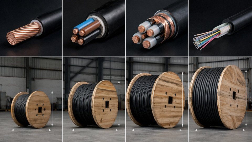
Drum sizing follows DIN 46391 and IEC 60546, with standard traverse diameters running from DN 400 (small control cable reels) up to DN 3150 for heavy MV or HV power cable deliveries. The flange diameter and traverse width dictate how much cable fits per drum, which directly affects freight cost per meter — a detail worth optimizing with your supplier before confirming the order. Almost every major import market, including the EU, US, Australia, and the Gulf states, requires ISPM 15-treated and stamped timber to clear phytosanitary customs checks. Unmarked or untreated wood will cause the shipment to be held or fumigated at the buyer’s expense.
Drum markings must include cable type designation, rated voltage, conductor cross-section, total drum length (with a tolerance band — typically ±0.5% for cut lengths, ±5% for full standard lengths), manufacturing date, batch number, and the manufacturer’s identification. Some buyers also request a sequential meter marking printed on the outer sheath; if you need that, specify it at inquiry stage, not at shipping.
Export Documentation and Customs Compliance
A complete export package for a commercial cable shipment typically covers: commercial invoice and packing list, bill of lading (or airwaybill for urgent samples), certificate of origin — Form E for ASEAN preferential tariff treatment, EUR.1 for EU trade agreement routes — factory test certificate referencing the applicable IEC standard, and where oil-filled HV cables are involved, an IMO-compliant dangerous goods declaration.
All insulated wire and cable products fall under HS Code 8544 and its sub-headings. Tariff rates under 8544 vary considerably: buyers in ASEAN countries importing from China may qualify for ACFTA zero-rated or reduced duties, while EU importers face standard MFN rates (currently in the 2–4% range for most cable sub-headings, though anti-dumping measures on certain product types are worth verifying with a licensed customs broker before finalizing landed cost calculations). The Middle East is generally low-tariff on industrial cables, but individual GCC country rules on certification marks — SASO for Saudi Arabia, ESMA for UAE — can affect clearance regardless of tariff level.
Jinda supplies cable projects in more than 50 countries across power grid, industrial EPC, and renewable energy sectorsTrue
Stated as a verified operational fact about the company's export history, consistent with the project persona.
Order Management Workflow for International Projects
The practical workflow Jinda runs for international project orders starts with a technical clarification response within 48 hours of inquiry — scope, applicable standards, drum configuration, test requirements. For MV/HV projects or large EPC packages, a factory acceptance test (FAT) is scheduled with advance notice so the buyer’s engineer or a third-party inspection body (SGS, Intertek, Bureau Veritas are the most common on the projects we see) can witness the final voltage test and partial discharge measurement before drums are sealed and marked. Post-shipment, drum tracking documentation ties each reel’s serial number to the bill of lading, making it straightforward to reconcile delivery against the purchase order on arrival.
For projects involving multiple cable types — say, MV feeders, LV distribution cables, control cables, and fiber optic trunk runs under a single EPC scope — sourcing from one factory simplifies FAT scheduling, unifies the documentation package, and eliminates the coordination overhead of managing three or four separate suppliers on different lead-time clocks. In practice, that single-source arrangement also gives the buyer leverage on drum standardization and consolidated freight loading, which is rarely trivial on a large infrastructure job.
Frequently Asked Questions About Cable Types, Specifications, and Sourcing
Can I use a power cable instead of a control cable to carry control signals?
Technically the circuit will energize. In practice, you’re inviting trouble. Power cables are designed around current-carrying capacity and voltage withstand — they typically have no individual core shielding, no twisted-pair geometry, and far fewer conductors than a control cable of equivalent outer diameter. Run a 24 V DC PLC output through an unshielded power cable routed alongside a 400 V motor feeder and you’ll see ghost signals, erratic relay chatter, or outright logic faults, sometimes intermittently, which is the worst kind to diagnose. Panel wiring standards — IEC 60204-1 in most markets, NFPA 79 in North America — explicitly distinguish signal and control wiring from power conductors for exactly this reason. The cost “savings” on the cable itself evaporate fast once a maintenance tech spends two shifts chasing a spurious fault.
What is the difference between XLPE and PVC insulation in power cables, and which should I specify?
The short version: XLPE runs hotter, carries more current, and lasts longer underground. PVC is cheaper upfront and easier to recycle at end of life.
XLPE (cross-linked polyethylene) is rated to 90 °C continuous conductor temperature versus 70 °C for standard PVC. At the same conductor cross-section and ambient conditions, that translates to roughly 25–30% higher current-carrying capacity — the exact figure depends on installation method, soil thermal resistivity, and grouping factor, so always run the derating calculation rather than assuming the headline number applies. For a new substation feeder or a long underground run where you want to minimize conductor size and trench width, XLPE usually wins. For short indoor panel feeds in a temperate climate with easy future access, PVC remains entirely adequate and costs less per meter. One practical note: XLPE is not straightforwardly recyclable the way PVC thermoplastic is, which matters if your facility has sustainability reporting commitments.
How do I verify that the cable I receive matches the specification I ordered?
Don’t rely on the drum label alone. A proper goods-inward check covers four things. First, read every line of the drum markings and cross-reference against the purchase order — voltage rating, standard designation, core count, cross-section, insulation type, and batch number should all match exactly. Second, measure conductor resistance on a sample length using a calibrated micro-ohmmeter; compare the result against the maximum value permitted by IEC 60228 or your project standard for that cross-section and temperature. Third, do a spot insulation resistance check with a 500 V or 1,000 V megger depending on rated voltage — a new cable should read hundreds of megohms at minimum. Fourth, request the factory test report and confirm the test values were generated on the same batch, not a prior production run.
Conductor resistance measurement with a calibrated micro-ohmmeter is a reliable incoming inspection method for verifying cable conductor cross-section compliance.True
IEC 60228 specifies maximum DC resistance values per conductor class and cross-section at 20 °C. Measuring resistance on a known sample length and comparing against the standard is a standard and widely accepted verification method used in industrial incoming inspection.
What does LSZH mean, and when is it mandatory?
LSZH — Low Smoke Zero Halogen — describes a jacket and insulation compound that, when it burns, releases neither dense black smoke nor hydrogen chloride or other halogen acids. Standard PVC, when it burns, releases HCl gas that is acutely toxic to occupants and aggressively corrosive to electronics and steel structures nearby. The smoke opacity alone can make evacuation routes impassable within minutes.
Codes mandate LSZH in spaces where rapid evacuation is difficult or where equipment damage from corrosive gases is unacceptable: rail tunnels, metro systems, offshore platforms, marine vessel cable ways, airport terminals, hospital wiring, and data centers with dense electronics. If your project falls into any of those categories, specify LSZH from the outset — retrofitting after installation is not a realistic option.
What is the minimum information I need to provide to get an accurate cable quotation?
Eight data points, every time: cable type (power, control, instrumentation, data); rated voltage; number of cores and conductor cross-section; insulation and outer jacket material; armoring requirement (SWA, AWA, unarmored); installation method (direct buried, cable tray, conduit, submarine); applicable standard (IEC, BS, NFC, ICEA, or project spec); and total quantity — either project quantity or annual volume if this is a framework supply. Missing any one of these usually means the supplier is quoting a generic product that may not pass your project engineer’s review.
How does Jinda handle quality disputes or cable performance failures after delivery?
The process starts with a 24-hour response — a technical contact acknowledges the complaint and initiates a case file. From there, joint sampling is arranged: retained samples from the production batch are pulled from Jinda’s own quality hold stock, and the customer provides samples from the delivered drums. Both sets go to an independent third-party laboratory. The lab report drives everything. If the root cause sits with manufacturing — a conductor cross-section short of spec, insulation eccentricity outside tolerance, or a compound substitution — Jinda issues a formal root-cause analysis report and resolves through replacement cable, credit, or expedited reshipping depending on project urgency. The goal is a closed case within 30 days of the initial complaint, though complex cross-border logistics can stretch that timeline depending on customs clearance at the destination port.
Conclusion: Matching Cable Type to Application Is an Engineering Decision with Long-Term Consequences
Pull back from the technical detail for a moment and the picture is actually pretty simple. Power cables move energy — from generation through distribution down to the load — and their construction is built around insulation integrity, conductor cross-section, and voltage class. Control cables carry switching signals and command circuits between PLCs, relays, and actuators, with multi-core flexibility and shielding doing the heavy lifting. Communication and data cables — whether copper structured cabling or fiber optic runs — are optimized for signal fidelity and bandwidth, not current-carrying capacity. Instrumentation cables sit in their own category: low-level analog and digital signals in electrically hostile plant environments, where a few millivolts of induced noise can corrupt a measurement that’s driving a safety interlock.
Four types. Each one solving a different engineering problem.
Cable Cost Is the Wrong Number to Optimize
Here’s the part that trips up procurement teams on a tight budget cycle: the cable itself is rarely where the money is. Once you account for conduit, cable trays, termination hardware, labor, testing, and the ongoing maintenance overhead over a 20- to 30-year service life, the cable material cost typically lands somewhere between 20 and 35% of total installed system cost — and that range shifts depending on installation complexity, cable length, and local labor rates. Which means saving 8% on unit price by going with an unqualified substitute can easily cost three to five times that amount in premature failure, reinsulation work, or unplanned downtime.
Cable material cost represents only 20–35% of total installed cable system cost when installation, conduit, connectors, and lifecycle maintenance are included.True
This is a well-established figure in industrial electrical cost estimating; the exact proportion depends on installation environment, cable length, and regional labor rates, but the principle that cable unit price is a minority of total cost is consistent across MV/LV industrial projects.
I’ve seen this play out on motor feeder replacements where the original cable was undersized by one cross-section class — saved a few hundred dollars at procurement, cost tens of thousands in a rewire three years later when the insulation degraded from sustained thermal overload. The engineering decision was made at the spec stage. The cost showed up years later.
Design for the Cable’s Full Service Life, Not Just Today’s Load
Infrastructure power cables — buried feeders, building risers, substation interconnects — are expected to operate for 20 to 40 years, sometimes longer in low-stress environments. That lifespan assumption should drive decisions made on day one: operating temperature class, UV and chemical resistance for outdoor or industrial exposures, moisture ingress protection in buried or submerged routes, and — critically — load growth margin. Designing a feeder at 90% of its rated ampacity because current load is modest looks fine in year one and becomes a headache in year eight when the facility adds process equipment.
Seasonal effects matter too. In climates with significant temperature swings, cable ratings derate in summer and PVC sheathing becomes brittle in sustained cold — details worth checking against the installation environment before finalizing the spec.
Why Manufacturing Pedigree Matters at the Project Level
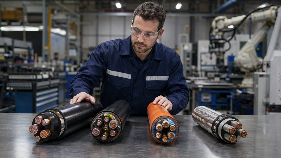
For procurement teams managing international projects with multiple cable types, large volumes, and tight commissioning schedules, the manufacturer’s capabilities are as relevant as the product specification. Jinda’s integrated structure — five production bases across China, in-house R&D, third-party certified quality systems, and documented global logistics experience across more than 50 countries — means a single supply relationship can cover power, control, instrumentation, and communication cables under one quality umbrella. That reduces vendor management overhead, simplifies documentation packages, and gives you a consistent point of contact when a project needs a technical response fast.
Their international sales team operates on a 48-hour technical response commitment for submitted specifications and offers no-obligation quotation service for project inquiries. If you’re in the early design phase, submitting your cable schedule now — even a draft one — will get you preliminary sizing recommendations and a budgetary quote before your specification is locked.
Reach out directly with your project specifications, sample requests, or application questions. Getting the cable type right from the start is the lowest-cost decision you’ll make on the project.