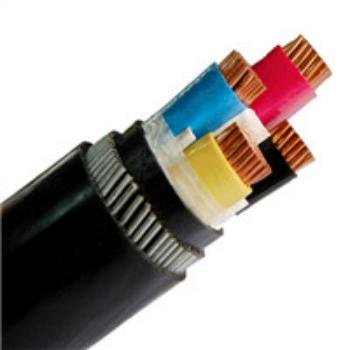
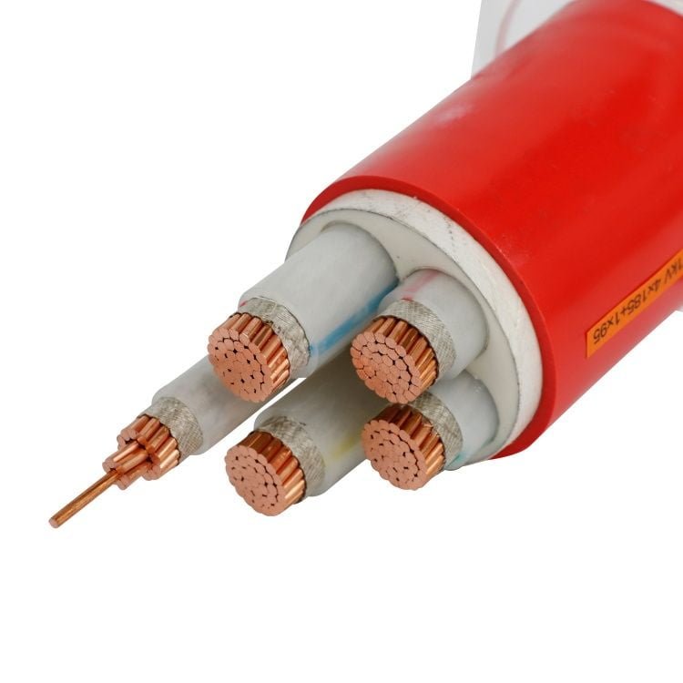
Specify “cable” when you mean “wire” on a purchase order and you may receive a single solid conductor where you needed a flexible, multi-core assembly — or vice versa. On the factory floor that mismatch translates directly into rework, conduit failures, or a failed FAT that delays commissioning by days. In procurement terms, wrong-spec material that clears goods-in and reaches installation is far more expensive than catching the error at the RFQ stage.
A cable is an assembly of two or more insulated conductors — or one insulated conductor with a protective sheath — twisted, stranded, or otherwise grouped together and covered by an overall jacket. A wire is a single electrical conductor, bare or individually insulated. Every cable contains wire, but not every wire is a cable. The distinction controls conductor class selection, current-carrying capacity calculations, and which installation standards apply.
What makes this genuinely complicated is that the industry itself uses the terms loosely — a “building wire” is sold as wire but often arrives as a multi-core cable, and “cable” sometimes refers to a single heavily-sheathed conductor in high-voltage work. Underneath the labeling conventions sits a real engineering structure: conductor geometry, stranding class per IEC 60228, insulation chemistry, and sheath design, all of which interact in ways that determine whether your installation runs reliably for 30 years or fails in the first wet season. Understanding that structure is where the useful answer actually starts.
The Internal Anatomy of a Cable: Conductor Types, Layers, and Their Engineering Functions
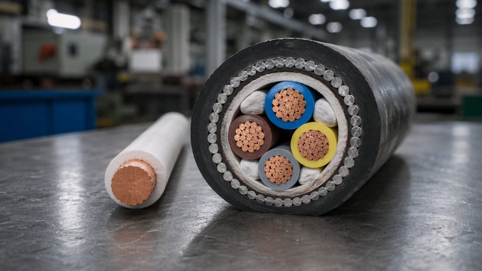
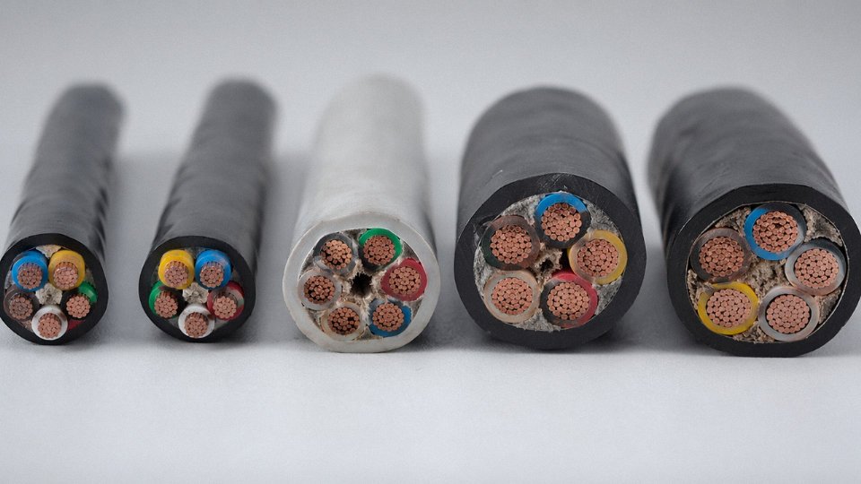
Crack open a cable cross-section diagram and you’re looking at anywhere from four to seven distinct functional layers, each solving a specific engineering problem. Knowing what each one does — and what happens when a cut-rate version substitutes in — is the difference between a 30-year installation and an expensive rework.
The Conductor Core: Solid vs. Stranded, and Why It Matters Operationally
The innermost element is the conductor, and the first decision is whether it’s solid or stranded. IEC 60228 Class 1 solid conductors are exactly what they sound like — one continuous wire, no gaps. They pack tightly, produce marginally lower AC resistance, and handle permanent fixed installations well. Conduit wiring in a commercial building, buried single-phase supply cables, motor terminal connections that never move. That’s their territory.
Stranded constructions — Classes 2 through 6 under IEC 60228 — bundle multiple thinner wires together, and that layered geometry distributes bending stress across many individual strands rather than concentrating it. Class 2 is standard for most power cable production worldwide; Class 5 and 6 are finer-stranded, intended for flexible cords and equipment cables subject to repeated flexing. If you spec a solid Class 1 conductor into a drag-chain application or a robotic arm, expect work-hardening fatigue cracks within months, not years.
Conductor Material: Copper, Aluminum, and the CCA Question
Annealed copper dominates — roughly 100% IACS conductivity, excellent solderability, and decades of connector and termination tooling designed around it. Aluminum runs at approximately 61% IACS conductivity, which means a larger cross-section is needed to carry the same current, but aluminum is about 30% lighter by weight and considerably cheaper per kilogram. That trade-off is why overhead transmission lines and large-cross-section buried power feeders frequently use aluminum; the installed cost math usually favors it above roughly 35–50 mm² depending on copper pricing at the time.
Copper-clad aluminum (CCA) sits in an awkward middle ground. The conductivity is better than bare aluminum, the price is lower than pure copper, and in low-frequency signal or power applications the performance is often adequate. The problem shows up at terminations: CCA work-hardens differently than copper, and standard copper-rated lugs can cold-flow under torque. In my experience, plants that switch to CCA without updating their termination procedure often discover intermittent high-resistance joints six to eighteen months later. Worth factoring into the total cost calculation.
IEC 60228 defines standard conductor cross-sections ranging from 0.5 mm² up to 2,500 mm²True
IEC 60228 is the internationally recognized standard governing conductor classes and dimensions for insulated cables; it specifies both the conductor classes (1 through 6) and the standard nominal cross-sectional areas used in cable production globally.
Insulation, Fillers, and the Layers You Don’t Notice Until They Fail
Each conductor gets wrapped in its own insulation. PVC is economical and rated to around 70°C continuous — fine for most general wiring, but it softens under sustained heat and becomes brittle in sustained cold below roughly −15°C. XLPE handles up to 90°C continuous service, resists moisture ingress better, and holds up under chemical exposure that PVC won’t. EPR (ethylene propylene rubber) stays flexible at temperatures down to −50°C or so, which makes it standard in cold-climate outdoor installations and offshore applications where PVC would crack during winter cable pulls.
Between the insulated cores and the armor, fillers like polypropylene rope or paper maintain a round cross-section under compression. Without them, cores migrate and the cable deforms under mechanical load — which creates uneven stress on insulation at bends.
Armoring and Outer Sheath
Steel wire armor (SWA) provides the mechanical protection needed for direct burial or cable tray installations subject to impact. Single-core cables, though, need aluminum wire armor (AWA) instead of steel; a steel armor on a single-core AC cable forms a shorted turn around the conductor and generates significant eddy current losses that eat efficiency and generate heat.
Steel tape armor (STA) is a lighter option — adequate for indoor multicore runs where you need crush resistance but not the full mechanical rating of SWA.
The outer sheath is the layer most visible to procurement but often least considered technically. General-purpose PVC covers most industrial sites. LSZH (low-smoke zero-halogen) is non-negotiable in tunnels, public transit infrastructure, data centers, and any confined space where a cable fire would trap people with toxic smoke. Polyurethane outer sheaths are the right call for drag-chain and oil-splash environments where PVC would swell and crack over time — the cost premium is real, but it’s far less than a cable replacement on a running production line.
Conductor Classification by IEC 60228 and NEC: What the Class Numbers Actually Mean
Most procurement specs just say “stranded conductor” and leave it there. That’s not enough. The class number — or the NEC insulation designation — determines whether your cable survives its installation environment for 20 years or fractures inside a conduit within a few months. Understanding what these classifications actually encode is the difference between a cable that performs and one that generates a warranty dispute.
IEC 60228: Four Classes You’ll Actually Encounter in Power Projects
IEC 60228 defines conductor classes based on construction — specifically, how many individual wires make up the conductor and how fine those wires are. The standard covers Classes 1 through 6, but in practice, Classes 1, 2, 5, and 6 cover the overwhelming majority of real installations.
Class 1 is solid conductor — one wire, no stranding. Cross-sections run from 1 mm² up to 2,500 mm² in standard production. It’s appropriate for fixed panel wiring, buried duct runs, and conduit installations where the cable is pulled once and never moved again. The minimum bending radius restriction is real and consequential: bend a 16 mm² Class 1 conductor too tight during installation and you create a stress concentration that weakens the conductor without any visible sign. Class 1 is cheap to manufacture and has slightly lower resistance per unit length than an equivalent stranded conductor (no geometric air gaps between wires), which is why it persists in switchgear and meter panel wiring.
Class 2 is stranded — multiple wires twisted together, ranging from 0.5 mm² up to 2,500 mm². This is the globally dominant class for power distribution cables, and for good reason: it’s flexible enough to pull through conduit bends and handle normal installation handling, while the stranding count is modest enough to keep costs and manufacturing tolerances manageable.
IEC 60228 Class 2 stranded conductors are used in the majority of power cable installations worldwide.True
IEC 60228 Class 2 is the baseline specification referenced in most national and international power cable standards, and it represents the default conductor construction for medium-voltage and low-voltage distribution cables across major markets including Europe, Asia, and the Middle East.
Class 5 steps up the flexibility significantly. Individual wire diameters drop substantially compared to Class 2 at the same cross-section — you’re looking at roughly twice the wire count or more, depending on the cross-section. This is the class for portable power cables, extension leads, machine tool connections, anything that gets coiled, dragged, and reconnected regularly. The finer stranding accommodates repeated bending without fatigue cracking.
Class 6 goes further still — the finest wire gauges, highest strand count, designed specifically for continuous movement: welding cables, festoon systems on crane tracks, robotic arm wiring, and similar dynamic applications. The conductivity per unit cross-section is slightly reduced versus Class 1 (air factor between fine wires), so cable cross-sections for Class 6 are sometimes specified one size up to compensate.
NEC Article 310: A Different Framework Entirely
North American practice under the NEC classifies conductors differently — primarily by temperature rating (60°C, 75°C, 90°C) and insulation type (THHN, THWN, XHHW, and so on) rather than by stranding class. Sizing uses AWG and kcmil rather than mm². A 4 AWG THHN conductor in a dry conduit is roughly analogous to a 25 mm² Class 2 installation in IEC terms, but the standards aren’t directly interchangeable — temperature correction factors and ampacity tables differ enough to matter on a large project.
Comparison: IEC Class vs. Wire Count vs. NEC Equivalent
| IEC Class | Typical Wire Count (10 mm²) | Flexibility Level | NEC Approximate Equivalent | Typical Application |
|---|---|---|---|---|
| Class 1 | 1 (solid) | Rigid | THHN solid | Panel wiring, fixed conduit |
| Class 2 | 7–19 wires | Moderate | THHN stranded | Power distribution, tray cable |
| Class 5 | 49+ wires | Flexible | SO/SOOW cord | Portable equipment, extension leads |
| Class 6 | 80–200+ wires | Extra-flexible | Welding cable (UL 62) | Welding, festoon, robotics |
Wire counts vary by manufacturer and cross-section; figures above are representative for 10 mm² / equivalent AWG sizes.
The Failure Mode Nobody Budgets For
Using Class 1 solid conductor in a flexible metal conduit that moves — even slightly, cyclically — is a documented failure path. The conductor experiences low-cycle fatigue at the point of maximum bending, typically near a fitting or clamp. Fractures develop internally, resistance rises, the termination runs hot, and the fault usually presents as an intermittent trip or a burned terminal block before anyone identifies the real cause. In field audits of installed systems, this failure pattern tends to appear in 18–36 months, well inside the warranty period but late enough that the original installer has moved on.
Specifying the right class upfront costs nothing. Replacing cables inside a live panel or a packed cable tray costs significantly more — in labor alone, often 8–15× the original material cost, depending on accessibility.
Seven Major Cable Categories and the Wire Construction Inside Each One
Not all cables are built the same, and the internal wire specification is what actually determines whether a cable survives its service environment — or fails in the first year. Here’s a practical map of the main product families, what sits inside each one, and why those construction choices exist.
Low-Voltage Power Cables (up to 1 kV)
The workhorses of building services and infrastructure. Most LV power cables use Class 1 (solid) or Class 2 (stranded) copper conductors, though aluminum is common in larger cross-sections (typically 35 mm² and above) where weight and cost matter more than termination convenience. Insulation is almost always XLPE or PVC — XLPE for anything with a meaningful thermal duty cycle, PVC where budget is the primary driver. Outer sheaths run PVC for standard building installations and LSZH wherever smoke toxicity matters, such as tunnels, hospitals, and metro systems.
Common designations include NYY (PVC/PVC), N2XY (XLPE/PVC), and SWA armored variants with a galvanized steel wire layer between sheath and bedding. SWA is the default choice for direct burial in most European and Middle Eastern infrastructure projects. Skipping armor to save cost on a cable that will be pulled through conduit under a road is the kind of procurement shortcut that causes expensive excavations two years later.
Medium-Voltage Power Cables (1 kV–35 kV)
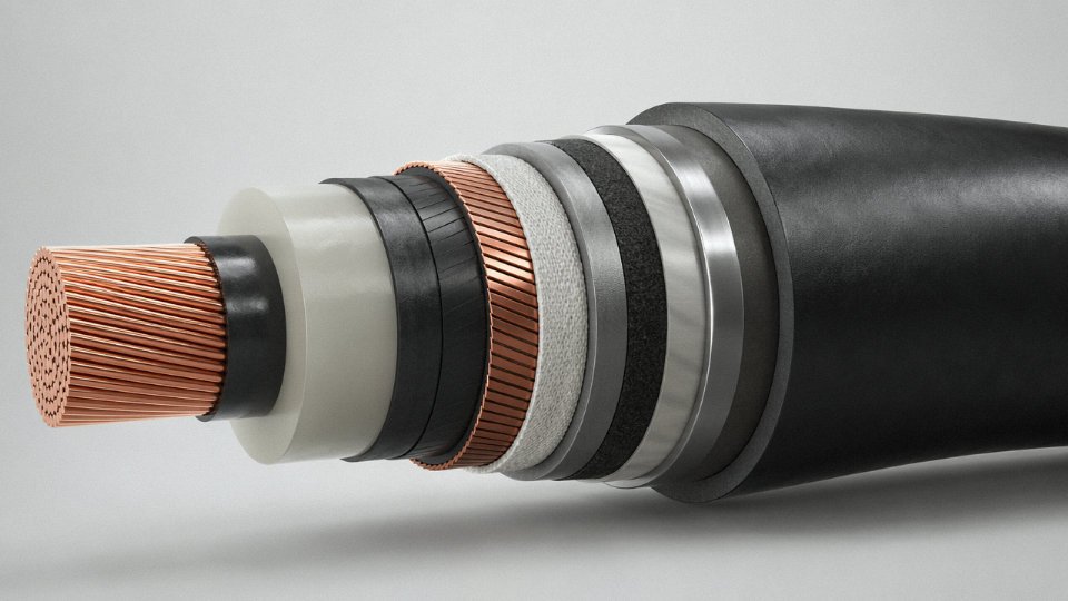
Construction complexity jumps considerably here. A typical MV cable cross-section adds a semi-conductive conductor screen over the conductor, then XLPE main insulation, then a semi-conductive insulation screen, then a metallic screen (copper tape or copper wire, depending on fault current requirements), and finally an outer sheath. Conductors are Class 2 copper or aluminum, same as LV.
Those semi-conductive layers aren’t optional decoration — they control the electric field gradient at conductor and insulation interfaces, preventing partial discharge that would degrade the XLPE over time. Specifying an MV cable without verified screen integrity on the datasheet is a meaningful risk, particularly for 11 kV and 33 kV utility feeders.
Control and Instrumentation Cables
Small conductors — 0.5 mm² to 6 mm², almost always stranded copper — color-coded per IEC 60446, bundled in counts ranging from a few pairs up to 40+ conductors. Signal integrity is the engineering concern, not ampacity. Overall braided or foil screens, or individually screened pairs for sensitive analog circuits, keep interference from adjacent power runs out of PLC and SCADA signal lines. Getting the screening topology wrong (overall screen where you needed individually screened pairs) usually shows up as intermittent noise on 4–20 mA loops — the kind of fault that takes days to diagnose.
Flexible and Trailing Cables
Class 5 or Class 6 conductors — many fine wires, rubber insulated (EPR or EV90 compound), with heavy-duty PCP or PUR outer sheaths. These cables are built for mechanical punishment: port cranes, continuous miners, mobile crushers. They must meet IEC 60245 or the HD 22 series. A trailing cable on mining equipment might flex through several million cycles over its service life. Using a standard fixed-installation cable in a trailing application shreds the conductor strands within months.
Fire-Resistant and Fire-Retardant Cables
The conductor wire itself is standard — Class 2 copper, nothing exotic. The difference is a mica tape wrapped directly over each conductor before the XLPE or LSZH insulation is applied. Mica is what maintains circuit integrity above 750°C; the outer jacket just provides normal service protection. Per IEC 60331, correctly constructed cables maintain function for 90–180 minutes depending on test category. That time window is what keeps emergency lighting and fire pump circuits alive during building evacuation.
Mica-wrapped fire-resistant cables can maintain circuit integrity at temperatures above 750°C for 90–180 minutes under IEC 60331 test conditions.True
IEC 60331 specifies flame exposure tests at 750°C minimum; mica tape insulation retains dielectric properties at these temperatures due to mica's thermal stability, and compliant cables are tested for circuit continuity throughout the rated duration (typically 90 or 180 minutes depending on the test category).
Data and Communication Cables
Twisted-pair data cables (CAT5e through CAT8) use 22–24 AWG solid or stranded bare copper, insulated with polyethylene or FEP. The twist rate per pair — tighter for higher categories — is the primary mechanism for crosstalk rejection, not the jacket material. Coaxial cables take a different approach: solid copper center conductor, foam PE dielectric controlling impedance (usually 50 Ω or 75 Ω), braided copper shield, PVC jacket. Using the wrong dielectric foam density changes the velocity of propagation and causes impedance mismatch at RF frequencies — a common problem with counterfeit or off-spec coax.
Submarine and Offshore Cables
These are built with an assumption of zero maintenance access for 25–30+ years. Conductors are Class 2 with water-swellable tape between strands — if the outer sheath is breached, the tape gels and limits water migration along the conductor length. A lead alloy sheath provides the primary radial water barrier. Double steel wire armor handles installation tension loads and protects against trawl gear and anchor strikes in shallower water. Polypropylene yarn serving protects the armor from corrosion. Every layer serves a specific long-term integrity function, which is why submarine cable costs per meter are in a completely different bracket from land cables of comparable electrical rating.
How Conductor Cross-Section and Stranding Are Calculated for Load-Bearing Applications
Sizing a conductor wrong costs money in one of two ways: oversize it and you’re paying for copper you don’t need; undersize it and you get nuisance tripping, accelerated insulation aging, or in a fault scenario, a fire. Neither outcome is acceptable. The calculation logic behind conductor sizing isn’t complicated, but it has several interdependent variables that suppliers don’t always surface clearly on a datasheet.
Current-Carrying Capacity (Ampacity)
Ampacity is governed primarily by IEC 60364-5-52 for installation methods and IEC 60287 for the thermal model. The core principle is heat balance — a conductor can carry current indefinitely only if the heat generated by I²R losses can dissipate fast enough to keep insulation below its rated temperature ceiling.
For a 95 mm² Class 2 stranded copper conductor in XLPE insulation (90°C rated), direct-buried at a soil thermal resistivity of roughly 1.0 K·m/W and ambient soil temperature of 20°C, you’d typically see ampacity in the range of 265–295 A depending on burial depth, grouping, and whether the cable has armoring. That 280 A figure that appears in many standard tables is a reasonable midpoint, but it assumes a single cable in undisturbed soil. Lay three circuits side by side and you’re applying grouping factors that can drag that figure down to 210–230 A. The aluminum equivalent — approximately 150 mm² — gets you to roughly the same ampacity because aluminum’s resistivity (≈2.82 × 10⁻⁸ Ω·m at 20°C) is about 64% higher than copper’s (≈1.72 × 10⁻⁸ Ω·m). Heavier cross-section, lighter weight, lower material cost per meter; the trade-off is real and worth doing the math on.
| Cross-Section (mm²) | Copper in Air (A) | Copper Direct-Buried (A) | Copper in Conduit (A) | Aluminum in Air (A) | Aluminum Direct-Buried (A) |
|---|---|---|---|---|---|
| 16 | 105–115 | 100–110 | 85–95 | 80–90 | 75–85 |
| 35 | 160–175 | 150–165 | 130–145 | 125–135 | 115–125 |
| 70 | 220–240 | 205–225 | 175–195 | 170–185 | 160–175 |
| 95 | 265–295 | 255–280 | 215–240 | 205–225 | 195–215 |
| 150 | 330–365 | 310–345 | 265–295 | 255–285 | 240–270 |
| 240 | 425–470 | 395–440 | 335–375 | 330–365 | 305–340 |
Values assume 90°C XLPE insulation, single circuit, 20°C ambient. Grouping, burial depth, and soil resistivity all shift these ranges — treat them as a starting point, not a final answer.
Voltage Drop
The formula most engineers use is ΔV = (ρ × L × I) / A, where ρ is conductor resistivity, L is one-way circuit length in meters, I is current in amperes, and A is cross-section in mm². IEC and most national codes cap voltage drop at 3–5% for final circuits — tighter limits apply when sensitive equipment like VFDs or PLCs is at the end of the run. In practice, a 200 A load over a 150 m circuit in 95 mm² copper comes out around 1.8–2.1% drop, which is comfortable. Stretch that same cable to 300 m and you’re at 3.6–4.2%, which starts to matter.
IEC and most national codes limit voltage drop to 3–5% for final circuits to protect sensitive equipment.True
IEC 60364-5-52 and IEC 60038 reference voltage tolerance limits, and national standards including BS 7671 and NEC Article 210 recommend or require voltage drop limits in the 3–5% range for branch circuits.
Short-Circuit Rating
The adiabatic equation S = I_sc × √t / k handles minimum conductor cross-section for fault survival. For copper with XLPE insulation rated to 90°C, k = 226. If a protection device clears a 20 kA fault in 0.1 s, minimum cross-section works out to roughly 28 mm² — meaning a 35 mm² conductor sized for ampacity will survive that fault with margin. Where this bites people is in low-impedance MV systems with very high prospective fault currents and slow upstream protection. Always check both ampacity and short-circuit rating; occasionally the fault rating governs the selection, not the load current.
Stranding Geometry and AC Resistance
Stranded conductors follow hexagonal packing: 7, 19, 37, 61, 91 wires per layer sequence. Each added layer increases overall conductor diameter by roughly twice the individual wire diameter. The lay length — how far along the cable axis one wire completes a full helix — affects both flexibility and AC resistance. Tighter lay (shorter pitch) improves flexibility but marginally increases AC resistance through the proximity effect.
At 50 or 60 Hz, skin effect and proximity effect push effective AC resistance above the DC value. For conductors up to about 150 mm² this correction is small — often under 3%. Above 300 mm² it becomes significant enough that IEC 60287-1-1 correction factors are mandatory in any serious design. Segmental conductors (typically four or six trapezoidal segments, sometimes called Milliken construction above 1,000 mm²) cut AC resistance by roughly 15–20% compared to an equivalent round stranded conductor. On a long submarine or underground transmission run, that reduction translates directly into operating cost over decades.
A quick operational warning: if a supplier quotes only DC resistance on a datasheet for a large conductor, ask specifically for AC resistance at your operating frequency. The omission is common and the difference matters.
Material Science of Wire Conductors: Copper, Aluminum, and Advanced Alloys Compared
Conductor material selection shapes almost every downstream decision — termination hardware, lug torque specs, conduit fill, long-term maintenance schedule. Most procurement conversations reduce this to a unit-price comparison between copper and aluminum, which misses a lot of operational reality. The metallurgy matters.
Electrolytic Tough-Pitch (ETP) Copper
ETP copper, at 99.9% purity, remains the default conductor for power cable and instrumentation cable worldwide, and for good reasons that have nothing to do with tradition. Its resistivity of approximately 1.72 × 10⁻⁸ Ω·m at 20°C, tensile strength in the 200–250 MPa range (depending on temper and wire diameter), and inherent corrosion resistance in most industrial atmospheres give it a reliability profile that competing materials have spent decades trying to match. Solderability is excellent; termination with standard lugs is forgiving; the conductor doesn’t demand anti-oxidant compound or special torque procedures at every joint.
In practice, ETP copper’s biggest vulnerability is theft on large projects and price volatility tied to LME spot pricing. That’s a procurement problem, not an engineering one.
Tin-Plated Copper
Tin plating — typically an electrodeposited layer of 1–5 µm — looks like a minor detail until you’re commissioning rubber-insulated cables in a chemical processing environment. Sulfur compounds in natural and some synthetic rubber compounds will attack bare copper over time, causing surface corrosion that increases contact resistance and eventually degrades the conductor-insulation interface. The tin layer prevents that reaction. It also improves solderability in high-vibration environments where solder joints are preferred over crimp connections. Specify tin-plated conductors for any rubber-insulated cable application, and for anything operating continuously above roughly 75–80°C where oxidation accelerates.
Annealed Aluminum (1350 Alloy)
Aluminum’s resistivity runs about 2.82 × 10⁻⁸ Ω·m — 64% higher than copper — which means for equivalent current-carrying capacity you need a larger cross-section, roughly 1.5–1.6× the copper area depending on the installation method and temperature rating. What aluminum recovers is weight: density of approximately 2,700 kg/m³ against copper’s 8,960 kg/m³. For overhead transmission lines and large underground distribution feeders, that weight difference drives the economics decisively. A 400 mm² aluminum feeder weighs a fraction of its copper equivalent; the mechanical tension loads on towers drop accordingly, and so does the installed cost.
The termination discipline, though, is non-negotiable. Aluminum oxidizes quickly in air, and aluminum oxide is a poor conductor. Every aluminum termination needs a proper aluminum-rated compression lug, correct die, and anti-oxidant compound worked in before the lug is crimped. Skip any one of those steps and you get a high-resistance joint that runs hot, accelerates further oxidation, and eventually fails — sometimes destructively.
Aluminum conductors require larger cross-sections than copper to carry the same current.True
Aluminum's resistivity (~2.82 × 10⁻⁸ Ω·m) is approximately 64% higher than copper's (~1.72 × 10⁻⁸ Ω·m), so a larger cross-sectional area is needed to achieve equivalent conductance and current-carrying capacity.
AA-8000 Series Aluminum Alloy
The residential fires associated with aluminum branch-circuit wiring in the late 1960s and 1970s weren’t purely an aluminum problem — they were a creep problem. Pure 1350 aluminum creep-relaxes under the clamping pressure of a standard screw terminal over time, loosening the connection and generating heat. AA-8000 series alloys (AA-8030, AA-8176) address this through alloying additions — iron, copper, trace elements — that significantly reduce creep rate at operating temperatures. NEC 310.106(B) now explicitly permits AA-8000 conductors for building wire where aluminum is otherwise acceptable. Use them with CO/ALR-rated devices; don’t mix them with legacy aluminum termination hardware that wasn’t rated for alloy conductors.
Copper-Clad Aluminum (CCA)
CCA gives you an aluminum core with a metallurgically bonded copper cladding, so the outer surface behaves like copper at termination points — standard lugs, no anti-oxidant compound required — while the bulk conductor is aluminum. Resistivity lands around 2.5 × 10⁻⁸ Ω·m, between the two pure materials. The application sweet spot is coaxial cable center conductors and some flexible cords where weight reduction matters but copper-compatible termination is needed. One practical caution: CCA’s current-carrying capacity in long feeders follows the aluminum core, not the copper skin, so size it accordingly.
Emerging and Specialty Conductor Materials
Silver-coated copper appears in high-frequency RF cable. Silver’s resistivity of roughly 1.59 × 10⁻⁸ Ω·m is the lowest of any common metal, and at GHz frequencies where the skin effect confines current to the outer conductor surface, that silver layer meaningfully reduces transmission losses. The cost premium is substantial — typically 20–40% over tin-plated copper at comparable gauge, depending on silver spot price — so it’s reserved for applications where signal integrity justifies it.
Nickel-plated copper handles high-temperature environments above 200°C, where tin would melt and bare copper would oxidize aggressively. Aerospace wire, kiln thermocouples, and certain industrial furnace cables commonly specify it.
Carbon nanotube composite conductors are still predominantly in R&D and pilot-scale testing. The theoretical conductivity-to-weight ratio is attractive for aerospace applications, but manufacturing consistency, termination methods, and long-term creep behavior under load cycles remain open questions. Worth watching, not yet worth specifying on a production project.
Industry-Specific Wire-Inside-Cable Requirements: Mining, Oil and Gas, Marine, and Renewable Energy
General IEC compliance gets you into the ballpark. Sector-specific standards are what keep people alive and plant assets running in environments where a cable failure doesn’t just mean a tripped breaker — it means a methane ignition, a flooded borehole, or a wind turbine nacelle grinding to a halt three kilometers offshore. Each industry below layers its own construction requirements on top of the general power cable specs already covered, and the differences are not cosmetic.
Mining Cables
Underground and surface mining environments combine mechanical brutality with chemical aggression and explosive-atmosphere risk — a combination that forces every construction decision. Conductors in trailing and reeling cables for mining equipment are specified to IEC Class 6 fine-wire stranding, partly for flexibility but primarily because these cables absorb continuous shock and vibration from shuttle cars, continuous miners, and drag shovels. Stiffen the conductor and fatigue cracking starts within months.
Insulation is almost universally EPR (ethylene propylene rubber), which tolerates water ingress far better than XLPE in flooded entries. The outer sheath — CPE or PCP — is chosen for resistance to crushing under heavy trackless equipment, tearing against rock faces, and degradation from mine water that can carry sulfates, chlorides, and pH extremes. One detail that surprises engineers new to mining procurement: most compliant mine cables include dedicated pilot cores or ground monitoring conductors woven into the assembly. These small-gauge conductors enable continuous earth continuity monitoring systems that trip the supply before a ground fault becomes a personnel fatality. In ATEX-rated zones (IEC 60079 series) or under MSHA rules in the US, this isn’t optional.
Oil and Gas
Upstream drill floor cables face hydrocarbon atmospheres, mechanical abuse, and drilling mud — a combination that demands IEC 60079-0 through -7 compliance for equipment and cable construction alike. Mud-resistant sheaths are a hard procurement requirement for any cable routed across a drill floor; standard PVC sheath fails within weeks in weighted barite mud.
Electric submersible pump cables are a specialized case worth calling out separately. ESP cables use a flat three-conductor construction — not round — because they must fit within the annular clearance of a production tubing string. The individual conductors carry lead alloy sheaths rated for well temperatures above 150°C and pressures that can exceed 500 bar at depth. The lead isn’t historical legacy; it remains the most reliable barrier against hydrocarbon gas permeation at those combined temperature-pressure conditions. Substitutes exist but come with trade-offs in long-term gas ingress performance.
Marine and Offshore
IEC 60092 series defines shipboard and offshore cable requirements, and the construction differences from land cables are substantial. IEC 60092-353 covers 0.6/1 kV shipboard power cables with EPR insulation and CSP (chlorosulfonated polyethylene) sheath — halogen-free, seawater-resistant, and capable of withstanding the ozone-rich atmosphere on exposed deck areas. Topsides and accommodation modules on offshore platforms require fire-resistant cables per IEC 60331, which specifies that the cable must maintain circuit integrity at 750°C or above for at least 90 minutes. Safety system circuits — fire and gas detection, emergency shutdown, lifesaving equipment — must keep working while the structure around them is actively burning.
Renewable Energy: Solar PV and Wind
PV DC string cables per IEC 62930 (the standard that replaced EN 50618) use tinned copper Class 5 conductors with XLPE or EVA insulation rated to 1.5 kV DC, housed in a UV-stabilized LSZH sheath. The tinning is there to resist the sulfur compounds that off-gas from some EVA encapsulants over a 25-year field life. Cross-sections are narrow — typically 4 mm², 6 mm², and 10 mm² for string and combiner box runs — but the UV and ozone exposure requirements are genuinely severe. A cable that passes general LSZH sheath testing can still fail after eight to ten years of direct Arizona or Saharan sun if the carbon black loading isn’t right.
Wind turbine cables have a completely different failure mode: torsional fatigue. The nacelle rotates ±180° or more as the turbine yaws, and the power and control cables running through the tower must absorb that rotation continuously for two decades. Class 6 stranding and helical lay construction distribute the torsional stress along the cable’s length rather than concentrating it. Get the lay pitch wrong and you’ll see individual wire breakage starting around year three to five, well inside the turbine’s design life. Offshore wind array cables operate at 33 kV and follow submarine cable routing to the offshore substation — a different product family entirely, with lead or copper water barriers and armoring suited for seabed burial.
EV Charging Infrastructure
IEC 62893 covers Mode 3 AC and Mode 4 DC fast-charging cables, and the construction reflects the abuse a public charging cable takes: dragged across wet pavement, run over, coiled improperly, exposed to diesel and de-icing fluid. Class 5 or Class 6 fine-wire copper conductors sit inside a PUR (polyurethane) sheath chosen specifically for flexural endurance — PUR outlasts PVC by a wide margin in repeated-bend applications. Beyond the power conductors, the assembly integrates pilot and proximity signal wires and, for chargers above roughly 350 kW, provisions for a liquid cooling channel running through the cable cross-section. Without active cooling at those current levels (up to 500 A sustained), conductor temperature management becomes the binding constraint on charge speed.
IEC 62930 replaced EN 50618 as the governing standard for photovoltaic DC cables and specifies tinned copper Class 5 conductors with UV-resistant LSZH sheathingTrue
IEC 62930:2017 is the current international standard for photovoltaic cables, having superseded the European EN 50618. It specifies conductor class, insulation type, and sheath requirements including UV resistance for outdoor PV applications.
Across all four sectors, the pattern is consistent: standard IEC construction is the starting point, and the industry-specific standard is where the real engineering lives. Specifying a general-purpose power cable in a mining trailing application or an ESP installation isn’t just a compliance failure — it’s a predictable path to early failure, unplanned downtime, and in some cases, incident investigation.
Reading and Verifying a Cable Datasheet: What Wire Specifications to Check Before Purchasing
A cable datasheet is a sales document first and a technical document second. That’s not cynicism — it’s just how procurement works in practice. The label on the drum and the printed spec sheet can both say “95 mm² copper Class 2, 0.6/1 kV” and still describe a product that will fail within three years on a busy distribution feeder. Knowing which numbers to interrogate, and which test reports to demand, is the difference between a smooth project handover and an unplanned outage tracing back to the cable itself.
Conductor Cross-Section: Resistance Is the Real Number
The nominal cross-section printed on a cable is not a measured dimension — it’s a performance class. IEC 60228 ties each nominal cross-section to a maximum DC resistance per kilometer at 20°C, and that’s what you should be verifying. A 95 mm² copper Class 2 conductor must measure no more than 0.193 Ω/km. If the test report shows 0.21 Ω/km, the conductor is undersized regardless of what the printing ink says. This matters for voltage drop calculations, for short-circuit rating, and for the protection coordination your protection engineer spent three weeks modeling.
Ask specifically for the conductor resistance test report, not just the type test certificate. A type test covers a product family; a production batch test covers the cable on your drum.
Insulation Thickness: Where Shortcuts Hide
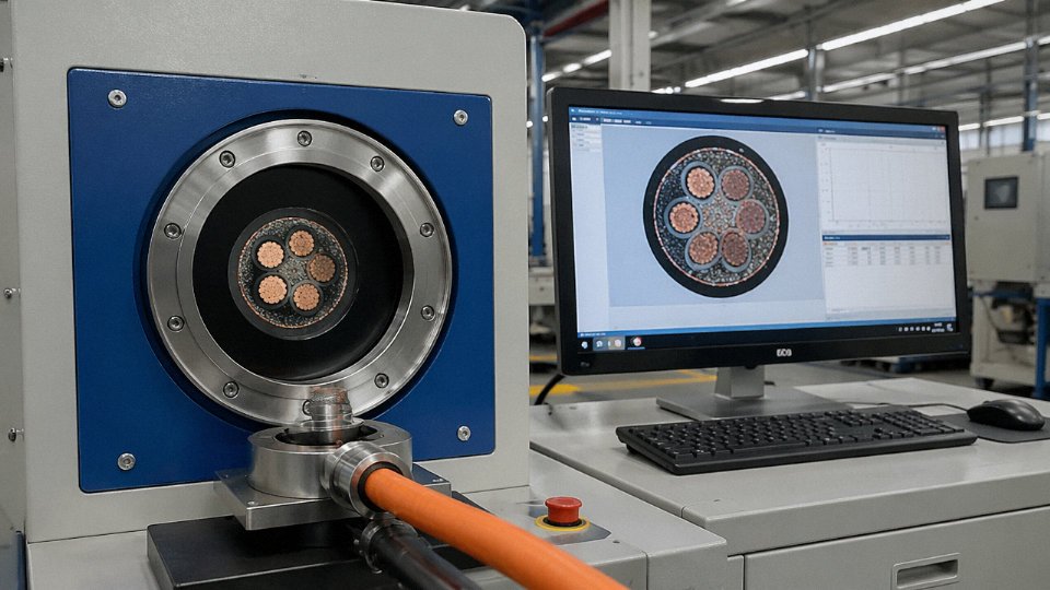
Thin insulation is one of the oldest quality shortcuts in the cable industry. IEC 60502-1 specifies both a minimum average thickness and a minimum point thickness for each voltage class and cross-section combination. A cable that meets the average but has thin spots — caused by an extruder running too fast or a worn die — can pass a quick visual check and still fail a dielectric test under sustained load.
Request a dimensional inspection report from a CNAS- or ILAC-accredited laboratory. These labs measure actual wall thickness at multiple points across a cross-section cut, which is the only reliable way to catch eccentricity. If a supplier can only produce a self-issued report, treat that as a yellow flag, particularly for medium-voltage or fire-rated applications.
Confirming What the Conductor Is Actually Made Of
Copper-clad aluminum (CCA) conductor mislabeled as solid copper is a genuine problem in spot-purchase markets, especially for imported product with unfamiliar brand names. The density of CCA is roughly 3.6–4.2 g/cm³ depending on cladding thickness, against 8.89 g/cm³ for pure copper — so a simple density check on a cut sample will catch gross substitution. A spark test (passing a flame along stripped conductor) causes CCA to oxidize visibly at the cladding boundary. For high-stakes procurement, request an EDX or ICP chemical analysis report confirming copper purity ≥ 99.9%, or the specific aluminum alloy grade for aluminum conductor types.
CCA conductor can be reliably distinguished from solid copper in the field using a density measurement or a controlled flame test on a stripped conductor end.True
CCA has significantly lower density than pure copper (roughly 3.6–4.2 g/cm³ vs. 8.89 g/cm³), and the aluminum core oxidizes with a characteristic white oxide when exposed to flame at the cladding interface — both are established field identification methods used by cable inspectors and acceptance testing engineers.
Voltage Tests: Production Records Matter as Much as Type Tests
Every insulated conductor should pass a continuous spark test during extrusion — a high-frequency AC voltage applied along the line that catches pinhole defects before the cable is wound. Finished cables then undergo a 4U₀ AC power frequency voltage test for five minutes per IEC 60502-1. These are pass/fail tests; ask for the actual production test records, batch by batch. A type test certificate issued two years ago on a slightly different construction tells you relatively little about the cable shipped last month.
Flame and Smoke Claims: Match the Standard to the Spec
“LSZH” and “fire-resistant” appear on marketing sheets loosely. Verify which specific test standard is cited: IEC 60332-1 (single vertical flame), 60332-3 (bunched cable flame propagation), 60754-1 (halogen acid gas emission, HCl equivalent ≤ 0.5% for compliant LSZH), or IEC 61034 (smoke density). A cable can pass 60332-1 without meeting 60332-3-22, which is what most building codes actually require for bundled tray installation. Mismatched certificates on a project tender can delay acceptance testing by weeks.
Third-Party Certificates: Scope Verification Is Non-Negotiable
KEMA, SGS, Bureau Veritas, and similar body certificates confirm a manufacturer’s capability and product compliance — but always for a defined scope. Check that the certificate explicitly covers the conductor cross-section, voltage class, and construction you are purchasing. It’s not unusual to find a certificate scoped to 16–240 mm² being cited for a 300 mm² or 400 mm² order. Jinda’s production facilities operate under ISO 9001 quality management systems across all five manufacturing bases, with in-house accredited testing laboratories and routinely issued English-language test reports aligned to IEC, BS, and NEC standards — which simplifies third-party submission for international EPC contractors who need documentation packages in a usable format rather than translated summaries.
A final practical note: build your purchase order to require test reports, not just a declaration of conformity. Specifying “test reports from CNAS- or ILAC-accredited laboratory to accompany delivery” is a single line that eliminates a large fraction of the quality disputes that otherwise show up at commissioning.
Frequently Asked Questions About Wire Inside Cables
Is a cable just multiple wires twisted together?
Not exactly, and conflating the two is how procurement mistakes happen. A cable is an engineered assembly: each conductor wire is individually insulated first, then the whole assembly receives additional layers — screens, armor, bedding, outer sheath — that bare or bundled wire simply doesn’t have. Twisting conductors in pairs or groups (as in a twisted-pair data cable or a three-core power cable) is one construction technique among several, chosen to manage electromagnetic balance or mechanical stability. The complete cable system provides electrical performance, environmental sealing, and mechanical protection simultaneously. Twisted wires in a conduit, without those outer layers, are not a cable.
Can I use single-core wire instead of a multi-core cable for the same load?
Only if your installation code permits it for the specific application, and the installation method has to be done correctly. Single-core cables running AC circuits create magnetic fields around each conductor. If those cables are routed separately through steel conduit, each cable induces eddy currents in the conduit wall — you get unexplained heating and possible conduit burn-through over time. Standard practice is trefoil or flat formation, all three phases touching or at defined spacing, with proper sheath bonding at both ends (or single-point bonding for longer runs to avoid circulating sheath currents). Get the bonding wrong and you get sheath corrosion, insulation stress, and eventually a fault. Multi-core cable keeps all conductors together and eliminates most of that complexity by design.
Why does a cable sometimes feel warm during normal operation?
Some warmth is normal. Resistive heating — I²R losses in the conductor — will always raise the cable’s surface temperature above ambient, and a cable running at, say, 70–80% of rated ampacity in free air might feel noticeably warm to the hand. That’s expected. What isn’t normal is a cable that’s hot enough to be uncomfortable to hold, or one that’s warm at a termination point but cool everywhere else (that’s a bad joint or loose lug). If you’re seeing unexpected heat, clamp-meter the actual current and compare it to the cable’s rated ampacity under its actual installation conditions — buried, bundled, ambient temperature. Insulation degradation also raises leakage current over time, generating heat at a level the original design didn’t account for.
What is the difference between stranded wire and solid wire inside a cable?
Solid conductor is one single piece of drawn metal. It’s slightly cheaper per meter to produce and has marginally lower DC resistance for the same cross-section, which matters for very long fixed runs at small cross-sections. But bend it repeatedly and it fractures — solid conductors in Class 1 are strictly for fixed installation. Stranded wire distributes mechanical stress across many individual wires, so any single strand absorbing a flex cycle doesn’t kill the conductor. IEC Class 5 stranded conductors, which use much finer individual wires, can survive tens of thousands of bending cycles without measurable degradation. Flexing robots, drag chains, and portable equipment all need at minimum Class 5; some continuous-flex applications need Class 6 with fine-strand construction and specialized lay geometry.
How do I identify conductor cross-section if the cable print is worn off?
Strip a short section, measure the outer diameter of the bare conductor bundle with a caliper, and calculate: area = π/4 × d². Cross-reference the result against IEC 60228 tables, keeping in mind that stranded conductors will read slightly larger than nominal due to interstices between strands. A more reliable field method: cut exactly 1 meter of conductor, strip it cleanly, and weigh it. Copper runs at roughly 8.89 g per mm² per meter; aluminum at roughly 2.70 g per mm² per meter. A 16 mm² copper conductor should weigh approximately 142 g per meter, give or take a few grams depending on stranding class. If the weight is significantly off, you may have an undersized or adulterated conductor — a real concern worth checking on unfamiliar supplier stock.
Copper conductor weighs approximately 8.89 kg per mm² cross-section per kilometer, which allows field identification of conductor size by weighing a stripped 1-meter sample.True
This follows directly from copper's density of approximately 8,890 kg/m³ and is a standard field-verification method referenced in cable engineering practice.
Does the number of cores in a cable affect the wire gauge I need?
Yes, and this is probably the most commonly underestimated derating factor at the specification stage. Conductors sharing a common enclosure contribute heat to a shared thermal environment. IEC 60364-5-52 provides grouping correction factors that account for this: five loaded single-phase circuits in one conduit, for example, can carry a derating factor in the range of 0.55–0.65 depending on arrangement, which means the conductor you’d normally select for that current isn’t adequate anymore. You need the next standard size up, sometimes two sizes. In practice, procurement teams often spec the conductor for the load alone and ignore grouping — then the cable runs warm from day one, aging the insulation faster than the design assumed.
What makes a special cable different from a standard power cable?
General-purpose power cables are designed for a defined envelope: rated voltage, rated temperature, standard mechanical handling. Special cables are engineered for stresses that fall outside that envelope — torsion in wind turbine towers, continuous flexing in drag chains, chemical resistance in offshore platforms, explosion protection in Zone 1 classified areas, or fire survival in evacuation routes. The wire construction inside those cables is often fundamentally different: finer stranding, specialized alloy conductors, specific lay angles optimized for torsion distribution, or insulation materials like silicone rubber or PTFE that no standard power cable uses. Jinda’s special cable division produces over 3,000 product variants covering these demanding applications across global industrial markets.
How long does a correctly specified and installed cable last?
IEC and CIGRE guidelines target a 30–40 year design life for medium-voltage XLPE cables under normal service conditions. In practice, actual service life depends heavily on operating temperature — the Arrhenius aging model says that sustained operation 10°C above rated temperature roughly halves insulation life, so a cable rated for 90°C but consistently running at 100°C ages at twice the expected rate. Installation quality matters almost as much: poor backfill with sharp stones, a bent termination that stresses the insulation near the lug, water ingress at a badly sealed joint — any of these can reduce a 30-year cable to a 10-year problem. Jinda cables are designed and tested for a 30-year service life in compliance with IEC 60502 and IEC 60840 requirements.
Selecting the Right Wire-and-Cable Solution: A Practical Decision Framework for Global Projects
Every section of this article has built toward one practical question: when a project lands on your desk, how do you actually choose the right cable? Not the cable that sounds right, not the one the distributor has in stock, but the one that will perform safely for the next 30 years without surprises. Here is the decision sequence that experienced procurement engineers and EPC contractors work through, usually in roughly this order.
Step 1: Lock Down the Electrical Parameters First
Before you look at a single datasheet, define U₀/U (voltage to earth and between conductors), maximum continuous current under worst-case load conditions, the prospective short-circuit current at the cable’s origin, and whether the site operates at 50 Hz or 60 Hz. These four numbers determine your conductor class, insulation voltage grade, and the floor for cross-section sizing. Everything else is secondary. Getting this wrong — say, specifying a 0.6/1 kV cable on a system where transient overvoltages regularly hit 1.5 kV — is the kind of mistake that doesn’t show up until year four when insulation breakdown starts.
Step 2: Environmental and Mechanical Parameters Define the Outer Construction
Direct burial in chemically contaminated soil demands something like an HDPE outer sheath over SWA armor; a cable routed in a ventilated cable tray in a 45 °C ambient machine room is a completely different specification. Go through the installation method systematically — buried, aerial self-supporting, tray, conduit, submersed, drag-chain — then overlay ambient temperature range, any oil or solvent exposure, UV index if outdoor, and mechanical impact class. These inputs lock in insulation compound (XLPE vs. EPR vs. PVC), armor type if any, and sheath material. Skipping this step is how projects end up with UV-degraded PVC sheaths cracking within 18 months in equatorial outdoor installations.
Step 3: Confirm the Applicable Standards Before the RFQ Goes Out
IEC, BS 6622, NEC, AS/NZS 5000 — these are not interchangeable. A cable built to IEC 60502-1 and submitted on a project specifying BS or NEC can be rejected at inspection even if it is physically superior. Mismatched standards are, in my experience, the single most common cause of cable rejection during third-party inspection on international EPC projects. Confirm the governing specification with the end client’s engineer before issuing any purchase order.
Step 4: Copper vs. Aluminum — Run the Numbers, Not the Habit
Copper’s conductivity advantage is real (resistivity roughly 1.72 × 10⁻⁸ Ω·m vs. aluminum’s ~2.82 × 10⁻⁸ Ω·m at 20 °C), but on long overhead distribution runs or large underground feeders above roughly 150 mm², aluminum often wins on total installed cost. The working rule: size aluminum at approximately 1.5× the copper cross-section to match ampacity and voltage drop. Factor in termination hardware — aluminum demands proper bi-metallic lugs and anti-oxidant compound, no shortcuts.
Step 5: Validate the Supply Chain, Not Just the Price
Request type test reports traceable to an accredited laboratory, factory acceptance test (FAT) records for your specific order, and agree on third-party inspection access before production starts — not after. For large-volume orders (500 km or more is not unusual on utility or offshore wind projects), confirm the manufacturer’s realistic production rate and reel delivery schedule against your site installation window. A three-week delivery slip on a critical cable package can idle an entire installation crew.
Step 6: Calculate Total Cost of Ownership Before Awarding on Unit Price
A cable priced 10% lower but carrying 15% higher resistive losses over a 30-year operational life typically costs considerably more in cumulative energy — the exact difference depends on load factor, local electricity tariff, and conductor length, but even at $0.08/kWh the arithmetic frequently reverses the apparent saving within the first decade. Run the installed resistance against your expected load profile before signing.
| Decision Step | Key Input | Output / Deliverable |
|---|---|---|
| Electrical parameters | U₀/U, Imax, Isc, frequency | Insulation grade, conductor class, min. cross-section |
| Environmental/mechanical | Installation method, temp, exposure | Sheath compound, armor type |
| Standards compliance | Project spec, end-client requirement | Applicable IEC/BS/NEC/AS revision |
| Material selection | Route length, cross-section, budget | Cu or Al, stranding class |
| Supply chain validation | Volume, schedule, test requirements | FAT plan, TPI access, delivery milestones |
| Lifetime cost | Load factor, tariff, conductor resistance | True 30-year cost basis for award decision |
Why Jinda Is Built for This Kind of Project Work
Shandong Jinda Special Cable Group has been manufacturing cables since 1987 — long enough that the engineers on the factory floor have seen most of the failure modes that happen when specifications are rushed or supply chain shortcuts are taken. Five production bases, 470,000 m² of manufacturing space, and over 1,000 technical and production staff mean the capacity exists to handle large project volumes without the schedule compression that causes quality drift.
Jinda serves customers in more than 50 countries with IEC-aligned test reports and English-language technical documentation.True
This aligns with the company's stated global sales network and standard practice for internationally traded cable products, where IEC compliance documentation and English-language datasheets are baseline commercial requirements.
For procurement managers working across power infrastructure, industrial plant, renewable energy, marine, or special application categories, Jinda offers OEM capability, flexible MOQ structures for both project-scale and repeat supply contracts, and after-sales technical support that extends beyond the delivery note. Getting cable specifications right the first time is genuinely cheaper than managing field failures — and that is the practical basis for any long-term supply partnership worth having.