Specify a cable incorrectly — wrong conductor material, undersized cross-section, insulation rated too low for the operating temperature — and the failure rarely announces itself cleanly. You get intermittent tripping, then a hard fault, then someone is standing in front of a production manager explaining why a line is down. Replacement cable sourced in a hurry costs two or three times the planned procurement price, and that’s before you account for the labor to rerun it through conduit or tray. Getting the fundamentals right at the specification stage is what prevents that conversation.
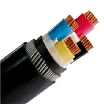
A cable works by enclosing one or more conductive cores — usually copper or aluminum — inside layers of insulation, shielding, and protective jacketing that together control electrical current flow, contain the electromagnetic field, protect the conductor from mechanical and environmental damage, and maintain safe, predictable performance across the cable’s rated voltage, temperature, and installation conditions.
What makes cables genuinely interesting from an engineering standpoint is that every layer in that stack is doing a specific job, and the choices made in each layer interact in ways that aren’t always obvious until something goes wrong in the field. The conductor material sets the electrical baseline. The insulation system defines the thermal ceiling and voltage class. The armor and jacket determine whether the cable survives its installation environment for 20 years or 5. Understanding how those layers work — individually and together — is what separates a cable specification that holds up from one that causes problems two years into service.
Anatomy of a Cable: How Every Layer Performs a Specific Electrical or Mechanical Job
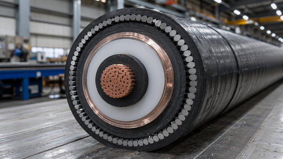
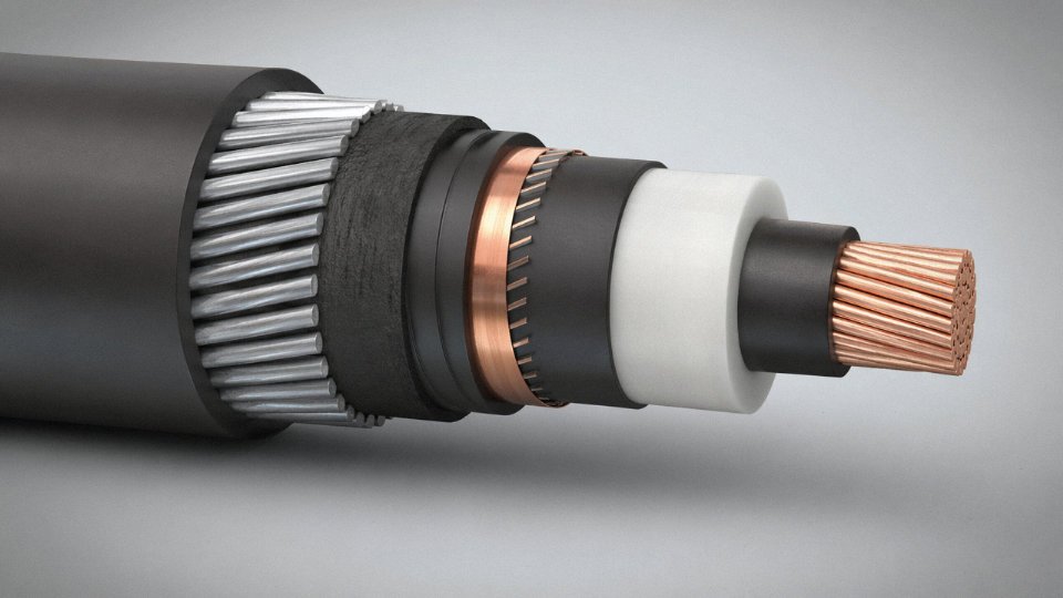
A cable isn’t a wire with some plastic wrapped around it. Every layer — conductor, shield, insulation, screen, armor, sheath — has a precise physical or electrical function, and the stack only works when all of them are present and intact. Pull out any one layer in your mind and trace the consequence forward; you’ll end up at partial discharge, ground fault, crush failure, or moisture ingress. Usually all four, eventually.
Conductor Core: Geometry Before Current Even Flows
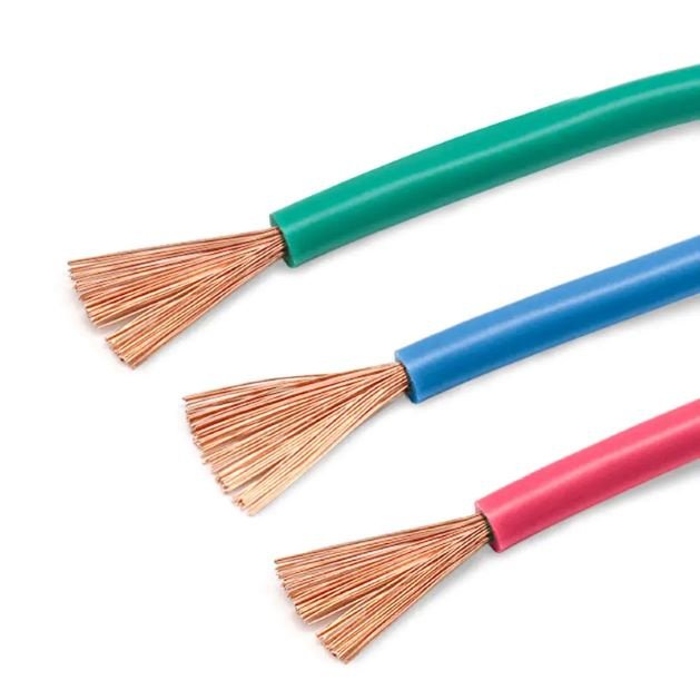
Solid conductors make sense below about 16 mm² — they’re cheaper, easier to terminate, and dimensionally stable under compression lugs. Above that, stranding becomes necessary for both flexibility and effective current distribution. IEC 60228 defines six conductor classes: Class 1 is solid, Class 2 is standard stranded for fixed installation, and Classes 5 and 6 are fine-wire flexible — the kind you’d use in a drag chain or a reeling cable on a crane. The class matters at procurement time because a Class 2 conductor specified for a fixed tray installation is meaningfully different from Class 5, even at the same cross-sectional area.
Stranding geometry is less visible but operationally important. Concentric-stranded conductors (wires in defined helical layers) keep current distribution uniform across the cross-section, which matters at higher frequencies or under heavy cyclic loading. Bunch-stranded configurations are more flexible but geometrically less predictable — fine for portable tools, less ideal where precise AC resistance calculations drive the design.
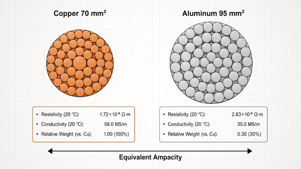
Copper’s conductivity benchmark of 58.0 MS/m at 20°C versus aluminum’s 35.0 MS/m isn’t just a specification footnote. It’s why a 95 mm² aluminum conductor needs roughly 150 mm² to carry the same current as copper in a given installation. That cross-section difference cascades into conduit fill, tray loading, and termination hardware — costs that don’t always show up in a cable unit price comparison.
Conductor Shield and Insulation Shield: Controlling the Electric Field
Medium- and high-voltage cables (generally above 3.6/6 kV) add a semiconducting layer directly over the conductor. Its job is to eliminate the micro-air-voids that form at the interface between a stranded conductor surface and the insulation. Left unfilled, those voids see electric field stress concentrated enough to ionize the air inside — partial discharge — and that erodes the insulation from the inside out, invisibly, over months or years until you get a fault.
The insulation shield on the outer face of the insulation does the mirror image of this: it ensures the radial electric field stays uniform and prevents stress concentrations at any surface irregularity. Remove or damage the insulation shield during installation — a careless knife slip during termination prep is the most common culprit — and you’ve created a stress riser that will eventually cause insulation failure at a voltage well below the cable’s rating.
Insulation Layer: Blocking Leakage Through Molecular Structure
XLPE handles continuous operating temperatures up to 90°C under normal load and can survive short-circuit conditions up to 250°C, which is why it displaced oil-impregnated paper in most new medium-voltage infrastructure from the 1980s onward. PVC is limited to 70°C continuous — adequate for many LV applications, but a cable running near the top of that range in a hot cable tunnel will age faster than its design life suggests. EPR lands between the two in thermal performance but outperforms both in flexibility at low temperatures, which is why it appears in offshore and Arctic installations where PVC would crack during handling.
Insulation thickness isn’t arbitrary — it’s calculated from the cable’s rated voltage and the material’s dielectric strength, with safety margins per IEC 60502 or IEEE 1202 depending on your market.
XLPE insulation can withstand short-circuit temperatures up to 250°C, compared to PVC's 70°C continuous ratingTrue
These values are defined in IEC 60502 and IEC 60228 standards. XLPE's cross-linked molecular structure prevents the material from melting or flowing under fault conditions, whereas PVC is a thermoplastic that softens progressively above its rated temperature.
Metallic Screen: Fault Return Path and EMI Shield
The concentric neutral or metallic screen serves two functions that are easy to conflate. First, it provides a low-impedance return path for ground fault current — its cross-sectional area is sized based on the expected fault current magnitude and the clearing time of the upstream protection. Undersized screens that burn open during a fault leave the system without a return path and create a shock hazard. Second, it attenuates electromagnetic interference both inward and outward, which matters near variable-frequency drives or instrumentation circuits.
Bedding, Armor, and Outer Sheath: Mechanical Hierarchy
Bedding — typically a extruded polymer or wrapped tape layer — protects the metallic screen from being chafed or punctured by the armor wires above it. Steel wire armor resists tensile loads during direct burial pulling operations and submarine laying; flat wire armor is more common in multi-core terrestrial cables while round wire armor dominates submarine and vertical riser applications. Armoring adds roughly 15–30% to overall cable diameter, and crush resistance improves to somewhere in the 450–900 N/cm range depending on wire diameter and lay angle — the actual figure depends on armor configuration and core geometry, not just nominal size.
The outer sheath — HDPE for buried or subsea applications, PVC for indoor or tray use — is the last line of defense against moisture, soil chemicals, UV, and mechanical abrasion. It’s often the layer that gets underspecified. A standard PVC sheath in a direct-buried coastal installation exposed to chloride-rich groundwater will blister and crack within a few years. Getting the sheath compound right is unglamorous procurement work that prevents expensive excavation later.
Conductor Materials and Geometry: Why Copper and Aluminum Behave So Differently Under Load
The conductor is where the electrical work actually happens, and the choice of material shapes everything downstream — cable diameter, joint hardware, installation labor, long-term losses, and total lifecycle cost. Getting this decision wrong at the procurement stage is expensive to fix later.
Copper: Why It Still Dominates Where It Matters
Copper’s resistivity sits at roughly 1.72 × 10⁻⁸ Ω·m at 20°C, which translates to a conductivity of about 58.0 MS/m. That figure isn’t just a textbook number — it means smaller cross-sections carry the same current, which saves conduit space, reduces bend radius requirements, and lightens the termination hardware. In mobile cables for cranes, festoon systems, and mining equipment, copper’s high ductility is equally important. Soft-annealed copper produced to IEC 60228 Class 5 or Class 6 achieves elongation well above 25%, sometimes reaching 30–35% depending on draw reduction ratio and anneal temperature. Hard-drawn copper, by contrast, might only hit 1–3% elongation — fine for overhead line spans but a liability in anything that flexes repeatedly.
Compression joints and lugs on copper are also forgiving. The metal cold-flows predictably under crimping force, and solderability is reliable enough that field splices hold up even in moderate corrosion environments. That reliability matters when a maintenance crew is working three meters up on a cable tray at 2 a.m.
Aluminum: The Economics Are Real, But So Are the Traps
Aluminum’s resistivity of 2.83 × 10⁻⁸ Ω·m means you need roughly 1.6× the cross-sectional area to match copper’s ampacity. A 95 mm² aluminum conductor is approximately equivalent to 70 mm² copper — and yet the aluminum cable is still about 30% lighter for that larger section, and raw material cost comes in roughly 40–60% lower depending on commodity market timing and alloy grade. For long MV feeder runs in an industrial park or a utility substation, that weight and cost difference is decisive.
The problem is oxidation. Aluminum forms a resistive oxide layer almost immediately on a fresh-cut surface. Leave an aluminum compression joint without anti-oxidation compound and you’re creating a high-resistance hotspot that will fail — slowly, then suddenly. Bi-metal lugs and inhibitor grease (Noalox or equivalent) aren’t optional; they’re mandatory. Any procurement spec that calls for aluminum conductors without specifying joint treatment and periodic thermal imaging for maintenance is incomplete.
Stranding Geometry and What the Lay Ratio Actually Does
A 19-wire concentric stranded conductor has one center wire, a first layer of 6, and an outer layer of 12. The cross-sectional area calculation isn’t simply 19 × (π/4 × d²) — the helical winding adds length per wire, so the actual metal cross-section is slightly less than the geometric sum. The lay ratio (helix pitch divided by conductor diameter) typically runs 6× to 14×, with shorter lay ratios producing more flexible but slightly higher-resistance conductors due to increased wire length. For power cables rated above 1 kV, a lay ratio around 10–12× is common. For flexible welding cable, you might push toward 6–8×.
At larger cross-sections — say, 300 mm² and above — AC resistance starts climbing noticeably above DC resistance because of skin effect and proximity effect. Current crowds toward the conductor surface, and adjacent conductor magnetic fields redistribute current density unevenly. The practical consequence in a 400 kV XLPE cable is that a solid or simple round-stranded conductor wastes material and generates excess losses. Segmental conductors (typically four or five keystone-shaped segments, each individually insulated with a paper or carbon-black tape) and Milliken conductors break up the current path geometry, keeping AC/DC resistance ratios close to 1.0 and cutting I²R losses meaningfully over a 30-year cable life.
Segmental and Milliken conductors are required in EHV cables above roughly 1,200 mm² to keep AC losses within acceptable limits for grid-scale transmission.True
IEC 62602 and standard EHV cable design practice confirm that segmental conductor construction is used in large cross-section HV and EHV cables specifically to reduce AC resistance by mitigating skin and proximity effects; this is not a vendor claim but a well-documented transmission engineering practice.
Specialty Conductor Options Worth Knowing
Copper-clad aluminum (CCA) splits the difference — an aluminum core with a copper outer layer, typically 10–15% copper by cross-sectional area. Conductivity lands somewhere between pure aluminum and copper depending on cladding thickness, and it’s used mainly in building wiring and coaxial cable where mechanical flexibility and cost matter more than peak current density. It is not appropriate for industrial power cable in environments with vibration or thermal cycling; the two metals expand at different rates, and that mismatch stresses the interface over time.
Tinned copper is a different story. The tin coating — usually 1–5 µm applied by hot-dip or electroplating — doesn’t meaningfully affect conductivity, but it creates a barrier against moisture-driven oxidation and sulfur attack. Offshore platforms, marine vessels, and coastal substations in high-humidity climates use tinned copper as a baseline, not a premium option. In practice, bare copper in a salt-spray environment will show green oxidation at terminals within a year or two; tinned copper in the same environment stays clean for the cable’s rated service life.
Insulation Systems Explained: How Dielectric Materials Stop Current from Going Where It Should Not
The conductor carries current. The insulation’s entire job is to make sure that current has absolutely nowhere else to go. That sounds simple until you understand what the insulation is fighting against.
Dielectric Breakdown: What Actually Fails and Why It’s Permanent
Every insulation material has an intrinsic dielectric strength — expressed in kV/mm — which represents the maximum electric field the material can sustain before the polymer structure collapses. Push past that threshold and the field starts ionizing molecular chains within the polymer. Free charge carriers form, a conductive path (called a treeing channel) propagates through the wall, and within milliseconds you have a direct short circuit through material that was supposed to be an insulator.
The critical point: this is irreversible. There is no “partially failed” insulation that recovers. A cable that has tracked through rarely survives even at reduced voltage, and in high-voltage plant environments it tends to fail catastrophically — arc flash, fire, or equipment destruction. Dielectric breakdown is one of those failure modes where the consequence logic is unforgiving. Get the voltage class wrong during procurement, or allow the insulation to degrade through heat cycling and moisture ingress over years, and you’re not looking at a slow drift in performance. You’re looking at a sudden, violent failure event, usually at the worst possible time.
PVC: The Workhorse That Has Real Limits
Polyvinyl chloride insulation covers an enormous share of building wire and light industrial cabling globally, and for good reason — it’s cheap, it accepts flame-retardant additives without major processing complications, and it’s mechanically forgiving enough to survive rough installation. Practical voltage rating tops out around 1 kV. Continuous operating temperature is limited to 70°C, which matters more than most people realize: in conduit bundles on a hot summer day in a poorly ventilated plant, ambient-plus-load can push surface temperatures uncomfortably close to that ceiling.
The plasticizer migration problem is underappreciated. PVC requires plasticizers to stay flexible, and above roughly 60–65°C those plasticizers begin migrating out of the compound, leaving the insulation brittle and prone to cracking. If you’ve ever pulled out 15-year-old PVC-insulated wire from a warm enclosure and had it shatter rather than flex, that’s exactly what happened. It’s not a material defect — it’s the material doing exactly what physics predicts.
XLPE: Why Cross-Linking Changes Everything
Standard polyethylene is thermoplastic: heat it enough and it softens and flows. Cross-linked polyethylene (XLPE) introduces covalent bonds between polymer chains — either through peroxide curing or silane moisture-cure processes — creating a three-dimensional network that does not melt or flow. The result is insulation rated for 90°C continuous operation, 130°C under emergency overload conditions, and up to 250°C during a short-circuit event.
XLPE insulation can withstand continuous operating temperatures up to 90°C and short-circuit temperatures up to 250°CTrue
These ratings are defined in IEC 60502 and IEC 60228, and are consistent with published conductor temperature limits for XLPE-insulated cables used in medium and high voltage applications.
That short-circuit rating is what displaced paper-oil (PILC) insulation in medium and high voltage cables starting in the 1970s and accelerating through the 1990s. Paper-oil cables are maintenance-intensive — joints must stay sealed against moisture, oil pressure must be managed, cold-climate installations require special handling. XLPE needs none of that. It’s also lighter, easier to terminate, and handles voltage classes from 1 kV straight up to 500 kV in EHV transmission cables. In my experience, any new MV installation specifying paper-oil today would raise questions at the engineering review stage.
EPR: The Choice for Wet, Cold, and Demanding Environments
Ethylene propylene rubber occupies a specific niche that XLPE doesn’t serve as well. EPR’s water absorption is genuinely lower, its flexibility at low temperatures extends down to around −50°C, and its resistance to electrical treeing in wet conditions makes it the preferred choice for mining cables, shipboard wiring, and nuclear plant applications where both flexibility and long-term moisture resistance matter.
The tradeoff is cost — EPR compounds run noticeably higher than XLPE — and the material is softer, so mechanical protection (braid, armor) is often required alongside it. For a coal mine dragline cable or a navy vessel power feed, that’s an acceptable equation. For a dry, climate-controlled data center, it probably isn’t.
Mineral Insulation: When the Cable Must Survive the Fire
MICC (mineral insulated copper-clad) cable is a different category entirely. Compressed magnesium oxide fills the annular space between a solid copper conductor and a seamless copper sheath. MgO is a ceramic — it does not burn, does not soften, does not carbonize. Continuous operating temperature can reach 250°C, and the cable will maintain circuit integrity through a fire scenario that would destroy any polymer-insulated alternative.
That property is the entire reason MICC exists. Fire-fighting pump circuits, emergency lighting feeds, smoke control systems — anywhere the cable must keep working while the building around it is actively burning. The installation is labor-intensive (special terminations required, moisture sealing critical at cut ends), and the cable is stiff and expensive. Nobody specifies it where they don’t have to.
Matching Insulation Wall Thickness to Voltage Class
IEC 60502 sets the nominal insulation wall thicknesses that procurement teams should treat as a baseline cross-check. Actual manufactured values depend on conductor size and screen configuration, but the figures below give a practical reference.
| Voltage Class (U₀/U) | Typical Insulation Wall Thickness |
|---|---|
| 0.6/1 kV | 0.7 – 1.0 mm |
| 3.6/6 kV | 3.4 – 4.5 mm |
| 6/10 kV | 4.5 – 5.5 mm |
| 8.7/15 kV | 5.5 – 6.5 mm |
| 12/20 kV | 6.5 – 8.0 mm |
These ranges widen with conductor cross-section. A 50 mm² conductor at 6/10 kV sits at the lower end; a 400 mm² conductor may require additional wall build to maintain the field gradient at acceptable levels. When reviewing supplier datasheets, any insulation wall that lands more than roughly 10–15% below the IEC nominal for its voltage class deserves a direct question before you sign a purchase order.
How Shielding and Screening Control Electric Fields and Block Electromagnetic Interference
Shielding means two fundamentally different things depending on where you are in the cable world. In medium- and high-voltage power cables, the screen exists to manage electric field geometry — it’s a dielectric engineering problem. In control and instrumentation cables, the shield is there to keep external noise out of a millivolt-level signal. Conflating these two functions leads to procurement mistakes that don’t show up until commissioning, when a VFD starts hammering a 4–20 mA loop or a 33 kV cable fails a partial discharge test.
Electric Field Grading in MV and HV Cables
Without a conducting screen at the insulation surface, the electric field inside a cable is not uniform. It peaks sharply at the conductor surface — sometimes by a factor of two or more compared to the field at the outer insulation boundary — because the geometry of a cylinder means field intensity is inversely proportional to radius. That concentrated stress at the inner surface is exactly where you can least afford it, since any imperfection in the insulation sits right at the worst possible location.
The semiconducting conductor screen, and its counterpart on the outside of the insulation wall, solve this by forcing the field to distribute radially and uniformly across the full insulation thickness. The outer screen also establishes a defined zero-voltage reference plane so the field terminates cleanly. In practice, both screens need to be intimately bonded to the insulation — no gaps, no microscopic separations.
Why Triple Extrusion Exists
Air voids as small as 50 µm at the conductor screen-to-insulation interface can initiate partial discharge at voltages well below the cable’s rated withstand level. The void ionizes, erodes the surrounding insulation over months or years, and eventually causes premature failure — sometimes catastrophically. You won’t see it on initial HV testing; it shows up on a partial discharge test or, worse, on a replacement invoice.
Triple extrusion — conductor screen, XLPE insulation, and insulation screen applied in a single continuous pass through a common crosshead — eliminates the handling steps between layers where contamination and separation occur. The interfaces are molecularly bonded rather than mechanically pressed together. For cables rated 11 kV and above, this is standard practice, not a premium option. Specifying single- or two-pass extrusion at medium voltage to save cost is a reliability gamble most operators eventually regret.
Triple extrusion eliminates interface contamination between the conductor screen and insulation, significantly reducing partial discharge initiation risk in MV/HV cables.True
The simultaneous co-extrusion of all three layers prevents any opportunity for surface contamination, moisture, or mechanical separation that would create micro-voids — the primary initiation sites for partial discharge in extruded dielectric cables.
Copper Tape Screen vs. Copper Wire Screen
These two metallic screen constructions serve the same electrical purpose but behave differently in installation and service. Tape screens — usually helically applied with a defined overlap — give lower screen resistance, a better moisture barrier, and more predictable fault-current return paths. That makes them the default choice for cables installed in ducts or troughs where moisture ingress is a long-term concern. Wire screens tolerate bending and flexing without cracking or losing continuity, which is why direct-buried distribution cables in uneven terrain typically use them. In practice, many 11–33 kV cables use a wire screen simply because the installation crew will not be gentle.
EMI Shielding in Control and Instrumentation Cables
A variable frequency drive generates common-mode noise that can easily dwarf a 4–20 mA signal. An aluminum-polyester foil shield with a drain wire — the construction you’ll find in the majority of instrumentation cables — achieves roughly 85–95 dB of shielding effectiveness at frequencies above 100 kHz under ideal conditions. That number drops with poor termination practice. If the drain wire is left floating at one end, or if the foil is pierced during gland installation, you are measuring noise.
Braid shields offer mechanical durability that foil cannot match, and coverage factor matters: a braid at 85–90% coverage leaves measurable gaps that affect transfer impedance at higher frequencies. For 95% coverage braids, high-frequency rejection is substantially better, though cost and cable diameter both increase. Triaxial cable — essentially a coaxial cable with a second independent braid over the outer jacket — appears in high-precision measurement loops where the inner braid carries signal return and the outer braid handles guard or noise absorption separately. It’s overkill for a process temperature loop but appropriate for strain gauge or vibration measurement circuits in electrically noisy machinery.
Grounding the Shield: Where Most Field Errors Happen
Single-point grounding at the receiving end prevents circulating currents in the shield conductor — correct practice for instrumentation cables. Ground at both ends and the shield becomes a shorted turn in whatever magnetic field the cable passes through, which induces a current that adds noise to the very signal you’re trying to protect.
High-voltage cable sheaths behave differently. Solidly bonding both ends of an EHV cable sheath creates circulating currents proportional to load current and cable length — on long runs this can represent meaningful sheath heating and real losses. Cross-bonding, used in EHV systems above roughly 66 kV on cable sections longer than 400–500 m, divides the route into three equal minor sections and transposes the sheath connections so the induced voltages in each third cancel out. The result is near-zero net sheath current without leaving the sheath sectionalized and vulnerable to overvoltage during a fault. It adds jointing complexity and requires careful sheath voltage limiter selection, but for long EHV cable circuits the energy savings and reduced thermal derating justify it.
How Cable Ratings Are Determined: Ampacity, Voltage Class, and Temperature Rise Calculations
Cable sizing is where theory meets consequence. Get it wrong in either direction — undersized or needlessly oversized — and you pay for it in trips, fires, or wasted capital. The engineering framework behind a cable’s current rating is fundamentally a heat transfer problem, and treating it as anything simpler is how plant engineers end up replacing cables two years into a project.
Thermal Equilibrium: The Core Physics
Every ampere passing through a conductor generates heat at a rate proportional to I²R. That heat has to go somewhere — through the insulation wall, across the bedding layers, through the armor, and finally into whatever medium surrounds the cable. Ampacity is the current level at which heat generation exactly equals heat dissipation, holding conductor temperature at or just below the insulation’s rated limit. For XLPE, that continuous limit is 90°C; for PVC, 70°C. Push past it and the insulation ages faster, sometimes catastrophically.
This is why the same physical cable carries meaningfully different currents depending on installation method. A 240 mm² copper 11 kV cable in free air might carry around 490–530 A; pull it into a concrete-encased duct bank and that figure can drop to 320–370 A. The cable didn’t change. The thermal path did.
IEC 60287 and Thermal Resistivity Values
IEC 60287 formalizes this using thermal circuit analogy — conductor heat generation treated like a current source, and each surrounding layer assigned a thermal resistance. Soil thermal resistivity is the dominant variable in most buried installations, and it ranges from roughly 0.7 K·m/W in wet, well-compacted sand to 2.5 K·m/W in dry, loosely packed soil. That’s not a small spread. A summer drought in a sandy site can push resistivity toward the upper end and quietly reduce safe ampacity by 15–20% relative to the design assumption. Concrete duct encasement sits around 1.0 K·m/W, which is more predictable — thermal backfill materials like Fluidized Thermal Backfill (FTB) are sometimes specified at 0.4–0.8 K·m/W to actively improve heat dissipation around direct-buried circuits.
Derating: Where Designs Get Trimmed Down
Grouping cables in a trench is where ampacity figures take their hardest hit. Each cable warms the soil around it, raising the ambient for its neighbors. IEC 60287 derating factors for grouped installations typically run 0.65–0.87, depending on the number of cables and the spacing between them. Three trefoil-laid cables touching each other in a trench sit at the severe end of that range. Add an elevated ambient temperature — say, a Middle Eastern installation where ground temperature at 1 m depth runs 35°C instead of the standard 20°C reference — and you’re applying two derating factors simultaneously.
Voltage Drop: The Other Sizing Constraint
Thermal limits don’t always govern. On long runs, voltage drop forces a larger conductor cross-section regardless of thermal capacity. The voltage drop calculation combines resistive and reactive components: V_drop = I × (R·cosφ + X·sinφ) × L. For a branch circuit the acceptable limit is typically 3–5% of nominal voltage, though some industrial specs tighten this to 2% for sensitive drives or instrumentation. A 2 km cable run at 11 kV carrying 260 A with a 0.9 power factor can accumulate meaningful reactive drop even on a medium-voltage circuit, and that sometimes drives the conductor to 300 mm² when thermal rating alone would have been satisfied at 185 mm².
Short-Circuit Rating and Screen Sizing
The adiabatic equation I²t = k²S² governs what happens during a fault. The conductor temperature spikes fast — too fast for heat to escape — so the cross-section S must be large enough to absorb the fault energy without melting. The k value depends on conductor material and starting temperature: roughly 143 for copper at 90°C initial, 94 for aluminum. Screen cross-section must go through the same check against expected earth fault current and fault clearance time. This is frequently overlooked in the early design phase.
The IEC 60287 calculation methodology uses thermal resistivity values for the surrounding medium as a primary input to determine cable ampacity.True
IEC 60287 is the internationally recognized standard for calculating cable current ratings, and soil or duct thermal resistivity is a central variable in its thermal circuit model — changes in this value directly shift the calculated ampacity result.
Working Through a Real Sizing Problem
Take a 3-core 11 kV XLPE SWA cable feeding a 5 MW offshore wind substation feeder, direct-buried over 2 km. Starting current is roughly 260 A at unity power factor. Base ampacity for 185 mm² copper in standard soil: around 395 A. Apply a soil resistivity correction for saturated marine clay (resistivity around 1.0–1.2 K·m/W — actually favorable), a depth-of-burial correction for 1.2 m, and a grouping factor if a parallel cable runs nearby. After derating, available ampacity might come down to 310–340 A — still adequate thermally. But running the voltage drop calculation at 260 A over 2 km with 185 mm² copper yields roughly 2.8–3.2% at peak load, which sits at the edge of the 3% limit. More importantly, a 2-second fault clearance time with a prospective fault of 12.5 kA demands a screen with adequate cross-section — a 16 mm² copper wire screen won’t survive that fault energy; 25 mm² is the practical minimum. The final selection lands on 3-core 240 mm² copper XLPE SWA, which resolves all three constraints with a reasonable margin and avoids future regret.
Cable Installation Methods and How the Physical Environment Changes Cable Behavior
Cable design gets you to the factory gate. What happens after that — how the cable is routed, pulled, buried, or racked — determines whether it runs at its rated capacity or spends its service life thermally stressed and heading toward a premature fault. The gap between nameplate rating and field performance is almost always an installation variable.
Direct Burial: Soil Is Not a Stable Thermal Environment
When a cable is buried directly, the surrounding soil becomes part of its thermal circuit. Soil thermal resistivity ranges from roughly 0.5 K·m/W in saturated sandy loam up to 3.0 K·m/W or more in dry, poorly graded backfill — a sixfold swing that directly compresses or expands the ampacity you can safely claim. The problem is that soil moisture content shifts with seasons, and a cable route that passed a thermal survey in spring may be running through near-dry soil by late summer. The conservative approach is to design to the worst-case dry season value for that geography, not the average.
Minimum burial depth requirements exist primarily to protect the cable from surface mechanical damage, not for thermal reasons. Most jurisdictions require 600 mm cover for low-voltage cables and 900 mm for medium-voltage installations under non-trafficked ground, with deeper requirements — often 1,000–1,200 mm — under roads or rail crossings. Even at those depths, excavation by third parties (a contractor digging for a water main, say) remains one of the leading causes of MV cable faults in urban networks. That is the actual driver behind armor selection for direct burial: not crushing load from soil overburden, which is modest, but the incidental pick-axe or bucket tooth.
Cable Tray and Ladder Rack: Fill Ratio Is Not Approximate
Tray installations give you accessibility and flexibility, but they come with their own derating logic. The standard guidance — fill ratio not exceeding roughly 40% of tray cross-sectional area for multi-layer power cable arrangements — exists because tightly packed cables cannot dissipate heat to the surrounding air effectively. The cables in the center of a dense bundle run hotter than their individual ampacity ratings assume. In practice, covered cable trays are significantly worse; the enclosed air above the cables can rise 10–15°C above ambient on a warm day in an unventilated plant area, pushing you further into derating territory.
Support spacing matters more than people expect. Flexible cables over 900 mm unsupported span start developing sag that concentrates mechanical stress at the support edges; rigid armored cables tolerate spans up to around 1,500 mm but will creep over years if the supports are too far apart and the cable is running warm.
Conduit and Duct Systems: Jam Ratio and Pulling Tension
Before pulling a cable through a conduit run, you calculate the jam ratio — the cable outer diameter divided by the conduit inner diameter. The accepted safe range is 0.55–0.85; below 0.55 the cable can roll and wedge diagonally, above 0.85 you risk binding especially at bends. This is a calculation people skip when substituting a cable size at the last minute, and the result is a pulled-down cable or damaged insulation screen.
Maximum pulling tension for a 16 mm² copper conductor cable runs around 1,500 N, scaling roughly with cross-sectional area. Sidewall pressure at bends is the more dangerous limit — exceeding around 3,000 N/m of sidewall pressure at a 90° sweep can deform XLPE insulation permanently, even if the cable appears undamaged externally. Proper pulling lubricant (not grease, which attacks certain jacket materials — use a cable-specific compound) reduces sidewall pressure by 30–50% in typical conditions.
Bending Radius: Where Installation Crews Do the Most Damage
XLPE cables require a minimum bending radius of 12–20× the overall cable diameter during the installation pull, depending on whether the cable is unarmored or armored. Once installed and fixed in place, that drops to 8–12×. These aren’t conservative numbers — they reflect the point at which the insulation screen begins to separate from the XLPE body or the armor wires kink and create a stress concentration. A kinked armor wire becomes a corrosion initiation point in wet environments and a mechanical notch that worsens with every thermal cycle.
Violating the minimum bending radius during cable installation can cause insulation screen separation in XLPE cables that is not visible externally but will result in partial discharge and eventual dielectric failure.True
XLPE insulation screen separation under overbending creates voids at the conductor-insulation interface. These voids initiate partial discharge under operating voltage stress, a recognized failure mechanism documented in IEC 60502 testing protocols and field failure analysis of prematurely failed MV cables.
In practice, the damage often happens at the cable drum during unreeling, not at the final installation point. A drum brake that stops too hard, or a drum laid flat on its side for unreeling when it should be rotating on its axis — that is where the first over-bend occurs.
Underwater and Submarine Routing
Submarine installation introduces catenary tension management as a core engineering variable. As the lay vessel moves forward and cable pays off the drum, the unsupported cable span between vessel and seabed must stay within controlled tension limits — typically held by a tensioner and monitored continuously. The armor wire count and lay angle in a submarine cable are engineered specifically for the target water depth and expected seabed conditions, not just for mechanical protection. For cables crossing trawl fishing grounds, post-lay burial by jet plow to depths of 1–3 m is the standard practice. Anchor drag protection in busy shipping lanes often requires both deep burial and heavy armor.
Thermal Expansion at Termination Points
A 100-meter run of medium-voltage cable will expand roughly 15–20 mm for every 10°C rise in operating temperature. Over the diurnal temperature swing in an outdoor installation or the load cycle in a lightly loaded industrial feeder, that movement adds up. Termination fittings that don’t accommodate this movement accumulate mechanical stress at the gland — eventually working the conductor connection loose or fatiguing the outer sheath. The standard mitigation is offset installation at termination points, leaving a shallow S-bend or expansion loop that allows the cable to move without transmitting force to the fitting. It looks slightly untidy. It prevents failures.
Testing and Quality Assurance: How Manufacturers Verify a Cable Will Perform to Its Rated Life
A cable that passes visual inspection and ships with a certificate is not the same as a cable that will last 30 years in a buried duct. The gap between those two outcomes is where testing lives — and where buyers get burned when they skip the verification step.
Type Tests, Routine Tests, and Sample Tests: Three Different Questions
IEC 60502-1 (low voltage) and IEC 60502-2 (medium voltage) establish a three-tier structure that experienced procurement teams should understand cold before signing a purchase order.
Type tests are design qualification tests. They are performed once per cable design — usually on a new construction or after a significant material change — and they answer the question: does this design, in principle, meet the standard? They are not repeated on every production run. Routine tests, by contrast, run on every completed reel before it leaves the factory: conductor DC resistance, high-voltage AC withstand, insulation resistance. If a manufacturer cannot show you routine test records tied to specific reel serial numbers, that is a problem. Sample tests sit in the middle — periodic destructive checks pulled from production batches to verify that the ongoing manufacturing process hasn’t drifted from the qualified design. Tensile strength, elongation, aging ovens. Things you cannot measure on a finished reel without cutting it open.
High-Voltage AC Withstand and What It Actually Catches
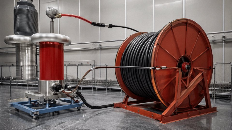
For completed medium-voltage cable reels, the standard AC withstand test applies 3.5 U₀ for five minutes across the full reel length. The physics here are unforgiving in a useful way: a microscopic void in the XLPE — something you’d never see on cross-section — concentrates the electric field enough to initiate partial discharge, which in a five-minute withstand at elevated voltage will escalate to full breakdown. The test is essentially a stress screen that collapses the timeline on a failure that would otherwise show up two years into service, probably at the worst possible moment.
Partial Discharge: The Real Indicator of Insulation Quality
Partial discharge measurement is, in practice, the most informative single test for XLPE-insulated MV cable quality. Sensitivity is typically 1–5 picocoulombs at 1.73 U₀ applied voltage. What it detects is localized ionization inside voids or at interfaces — activity that the withstand test might not immediately collapse but that will steadily erode insulation over time through treeing. Low partial discharge, consistently below the detectable threshold at that sensitivity level, is the definitive signature of proper triple-extrusion: conductor screen, insulation, and insulation screen co-extruded in a single pass without contamination or interface voids. A cable manufacturer who cannot quote you partial discharge levels from routine production testing is telling you something.
Mechanical Tests: Numbers That Must Hold Before and After Aging
XLPE insulation must meet minimum tensile strength of 12.5 N/mm² and elongation at break of at least 200% — and critically, those values must hold after aging at 100°C for seven days. The before-aging number tells you about the compound; the after-aging number tells you whether it will stay that way in service. Armor wire tensile tests verify the steel or aluminum hasn’t been drawn to brittleness. Bend tests over a specified mandrel diameter catch any tendency for insulation or sheath to crack under installation bending radii that are, honestly, often tighter in the field than the installer realizes.
Fire Performance: Three Tests, Three Different Hazards
IEC 60332-3 category C tests whether a cable installation resists flame propagation, not whether an individual cable is flame-retardant.True
IEC 60332-3 applies a 20-minute burner to a single-layer cable tray installation and measures how far the char propagates. An individual cable can pass IEC 60332-1 but fail tray testing — a distinction that matters enormously for cable routing in occupied buildings or process plants.
IEC 60754 measures halogen acid gas emission — for LSZH cables, HCl emission must stay below 0.5% by weight. IEC 61034 measures smoke optical density, requiring minimum 60% light transmittance; in an emergency evacuation scenario, that difference between 40% and 60% transmittance is the difference between people finding the exit and not finding it. These are not paperwork requirements. Specifying all three and requiring test reports from the actual production batch, not a generic type test certificate from three years ago, is standard practice on any project where fire load matters.
How Integrated Production Control Affects Batch Consistency
Jinda’s five production bases operate with R&D, raw material intake testing, extrusion, and finished reel verification under one quality management structure rather than outsourcing compound mixing or relying on third-party semi-finished materials. In practice, that integration means conductor resistance checks at wire drawing feed into the same database as final routine test results — so a material drift at intake gets caught before it becomes a nonconformance on a 500-reel bulk order. For international procurement managers placing large-volume orders across multiple production runs, that traceability from raw copper or aluminum through to reel-level test certification is what batch-to-batch consistency actually looks like in operational terms, not just in a brochure.
Special Cable Types and How Their Construction Is Engineered for Extreme Conditions
Standard power cable design assumptions — moderate ambient temperature, stable installation geometry, predictable mechanical loading — fall apart quickly once you move into mining drifts, subsea tiebacks, or a building actively on fire. Each specialized cable type below exists because a conventional design would fail, usually catastrophically, in that specific environment.
Mining Cables
Underground mining cables take abuse that would destroy most commercial designs inside a week. The outer sheath is CPE (chlorinated polyethylene) or CSP (chlorosulfonated polyethylene) — both rated for continuous flexing over sheave wheels and drum reelers, resistant to cutting oils, hydraulic fluid, and methane atmosphere. That last point matters enormously. In IEC 60079 Zone 1 and Zone 2 classified areas, the ground continuity conductor (GCC) isn’t just a protective earth — it’s specifically sized and monitored so that a single fault trips the circuit before an arc can ignite firedamp. The GCC is often run as a concentric ring or as discrete conductors symmetrically positioned around the phase cores, which also helps balance mechanical stress during repeated coiling.
Crush resistance in a typical armored mining cable runs 450–900 N/cm depending on whether steel wire armor or steel tape armor is used, and the outer sheath shore hardness is usually kept high enough to resist roof-fall debris without cracking. In practice, the sheath formulation is almost as important as the armor — a brittle sheath that crazes at low temperature or swells in oil will fail at the jacket level even if the armor is intact.
Fire-Resistant Cables
The construction logic here is straightforward but the execution is precise. Individual conductors get wrapped with mica tape before the XLPE insulation is applied. Mica’s crystal structure stays dimensionally stable well above 800°C; the XLPE burns away, but the mica tape maintains a continuous insulating sleeve around each conductor. IEC 60331 requires circuit integrity at 750–840°C for 90–180 minutes depending on cable class — long enough for evacuation lighting, fire pumps, and emergency voice systems to keep running through the worst of a structural fire.
One caveat: fire-resistant performance is highly installation-dependent. The same cable routed through a cable tray that retains burning debris beneath it may fail earlier than the type-test result suggests. The standard tests the cable; it doesn’t test your tray arrangement.
Low-Smoke Zero-Halogen (LSZH) Cables
Replacing PVC with EVA-based or HFFR compound cuts HCl and HBr emission below 0.5% by mass. That number matters because in a tunnel fire or metro station, toxic combustion gases typically cause more casualties than direct thermal exposure. The smoke opacity is also dramatically lower, which keeps evacuation signage visible. The trade-off is mechanical: LSZH compounds are generally softer and less abrasion-resistant than PVC, so installation in conduit with sharp bends requires more care. Pulling tension limits drop, sometimes meaningfully.
EV Charging Cables
A DC fast-charging cable carrying 400 A at up to 1 kV presents a combination of requirements that ordinary flexible cable can’t meet. The outer sheath is TPU rated from −40°C to +90°C — necessary because cables in northern climates spend winter nights on frozen ground and summer afternoons coiled on hot asphalt. Conductors are Class 6 stranded copper, finely stranded enough that the cable remains pliable after thousands of plug-connect cycles. Integrated into the same bundle are the pilot conductor and CP (control pilot) signal conductors for IEC 61851 handshake communication between vehicle and charger. Getting the signal conductors to sit stably inside a cable that’s also carrying 400 A DC requires careful geometric separation and, in better designs, an individual foil screen over the signal pair.
IEC 61851-compliant EV charging cables must integrate both power and control pilot conductors within a single cable assembly to enable vehicle-to-charger communication during active charging.True
IEC 61851-1 defines the control pilot circuit as mandatory for mode 3 and mode 4 charging, and the signal conductor is physically integrated into the charging cable assembly rather than run separately.
Instrumentation and Thermocouple Extension Cables
Type K extension cable uses chromel and alumel alloy conductors — not copper — because substituting copper would introduce a parasitic thermoelectric junction at the transition point, generating a voltage error that compounds over the cable run. At 300 meters, even a few microvolts of offset shifts the indicated temperature by several degrees, which in a combustion control or pharmaceutical process context is unacceptable. The conductor alloys are matched to within tight tolerances; cheaper “compensating” cable uses alloys that approximate the thermoelectric output rather than replicate it, and the difference shows up as systematic temperature bias, usually worst at the extremes of the measurement range.
Subsea Umbilicals
Subsea umbilicals are arguably the most complex cable assemblies in common industrial use. A single umbilical might carry 3-phase power conductors, individual signal and control conductors, one or more fiber optic bundles, hydraulic hose circuits for actuator control, and chemical injection tubing for hydrate inhibitor — all armored and bundled into something you can spool onto a lay-vessel reel and deploy to 1,500 meters of water depth.
The helical lay angle of each element is engineered specifically to balance torsional stiffness. Under installation tension — which can exceed several hundred kilonewtons for deepwater work — an unbalanced lay will cause the armor wires to either tighten into the bundle (birdcaging inward) or open outward, either of which damages internal elements. Getting that lay geometry right is a genuine mechanical engineering problem, not just a manufacturing parameter, and it’s one reason subsea umbilical qualification testing is substantially more involved than for any surface cable type.
Frequently Asked Questions About How Cable Wire Works
What is the difference between a cable and a wire?
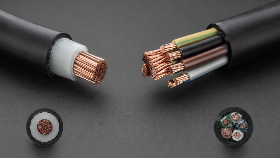
A wire is a single conductor — either solid or stranded — with or without basic insulation. A cable is an engineered assembly: either multiple insulated conductors laid up together, or a single insulated and jacketed conductor explicitly designed for a defined voltage class, installation environment, and mechanical duty. The distinction matters in procurement because calling a cable a “wire” on a specification sheet can result in receiving a product without the sheath, armor, or voltage rating the installation actually requires. In practice, most plant electricians use the terms interchangeably, which causes real problems when the purchasing order goes out.
Why does cable get hot under load, and is that normal?
Yes, it is normal — unavoidable, actually. Current flowing through any conductor with finite resistance dissipates energy as heat; the relationship is I²R, so doubling current quadruples heat generation. Cables are rated so that this heat stays within the thermal limit of the insulation system under the assumed installation conditions. The danger is sustained overtemperature. Insulation aging follows the Arrhenius model roughly: every 8–10°C above the insulation’s rated operating temperature cuts its service life approximately in half. A XLPE-insulated cable rated for 90°C that runs continuously at 100°C isn’t just running a little warm — it is burning through design life at roughly twice the intended rate. Check your ampacity calculations, and check your actual installation conditions against the assumptions those calculations used.
How long will a cable last in service?
IEC standards target a 40-year service life for medium-voltage XLPE cables at rated load under normal conditions. Real service life is messier. Operating temperature, installation quality, thermal cycling, moisture ingress, and whether anyone has ever accidentally trenched through it all matter. Partial discharge monitoring is worth considering on critical MV circuits after roughly 15–20 years — it can detect insulation degradation early enough to plan a planned replacement rather than respond to an unplanned fault.
Can aluminum cable be used everywhere copper cable can?
Not quite. Aluminum works well for fixed power distribution at 16 mm² and above — feeders, mains, overhead distribution. Avoid it in flexible applications; aluminum work-hardens and develops fatigue cracks at flex points far faster than copper. Below 16 mm², termination reliability becomes problematic and the conductivity penalty pushes conductor size up to the point where the weight saving disappears. You also need larger conduit, bigger junction boxes, and anti-oxidant compound on every lug. None of that is disqualifying for a large substation feeder run, but it adds up on a dense panel.
What does LSZH mean, and when is it actually required?
Low-smoke zero-halogen. When PVC burns, it releases hydrogen chloride gas — corrosive, toxic, and capable of incapacitating people before they can evacuate. LSZH compounds instead produce minimal smoke and no halogenic gases. Building codes and project specifications in underground railways, tunnels, airports, hospitals, offshore platforms, and data centers typically mandate LSZH because evacuation is constrained and smoke density is a life-safety factor, not just a comfort one. Specifying standard PVC in those environments because it is cheaper is a false economy.
LSZH cables produce significantly less smoke and no halogenic acid gases compared to PVC cables when burnedTrue
LSZH compounds are formulated from polyolefin-based materials that do not contain chlorine or bromine; IEC 60754 and IEC 61034 tests confirm negligible acid gas emission and reduced smoke obscuration relative to PVC insulation systems
How do I verify a cable supplier’s quality claims before placing a bulk international order?
Request IEC type test reports issued by an accredited third-party laboratory — not in-house test certificates. Ask for material certifications for the conductor metal and insulation compound. A factory audit, either in person or via a qualified third party, tells you whether the production process actually matches what the certificates describe. For large orders, witnessed factory acceptance testing on a production sample batch is standard practice and worth the travel cost. Jinda supports all of these steps for international procurement partners, including witnessed testing and documentation packages aligned to IEC and project-specific requirements.
What causes cable insulation failure, and how is it prevented?
Four mechanisms dominate. Thermal aging from chronic overloading is the most common and the most preventable — size cables correctly, verify installation derating, and monitor load growth. Moisture treeing in medium-voltage XLPE is insidious; water molecules diffuse into the insulation over years and create micro-channels that eventually cause dielectric breakdown. Dry-cured insulation and water-swellable tape designs significantly reduce this risk. Mechanical damage during installation — kinking, exceeding minimum bending radius, overstressing during pulling — is frequently underestimated and often invisible until the cable fails under electrical stress months later. Chemical attack on the outer sheath is straightforward to prevent but requires someone to actually check what the cable will be lying in: oil, UV, acids, rodents, and ozone each call for a different sheath compound, and getting that wrong is an expensive lesson.