Specify “cable wire” on a purchase order without understanding what that actually means structurally, and you will eventually receive a product that technically meets the written spec while failing completely in your application — wrong temperature rating, undersized conductor, incompatible insulation chemistry for the environment. That is not a hypothetical. A 95 mm² cable derated by a poorly chosen insulation type or an aluminum conductor where copper was operationally required can mean unplanned downtime measured in shifts, warranty disputes that drag on for months, and rework costs that dwarf whatever was saved on unit price. Getting the terminology right is not pedantry; it is the foundation of every procurement decision, installation standard, and safety case that follows.
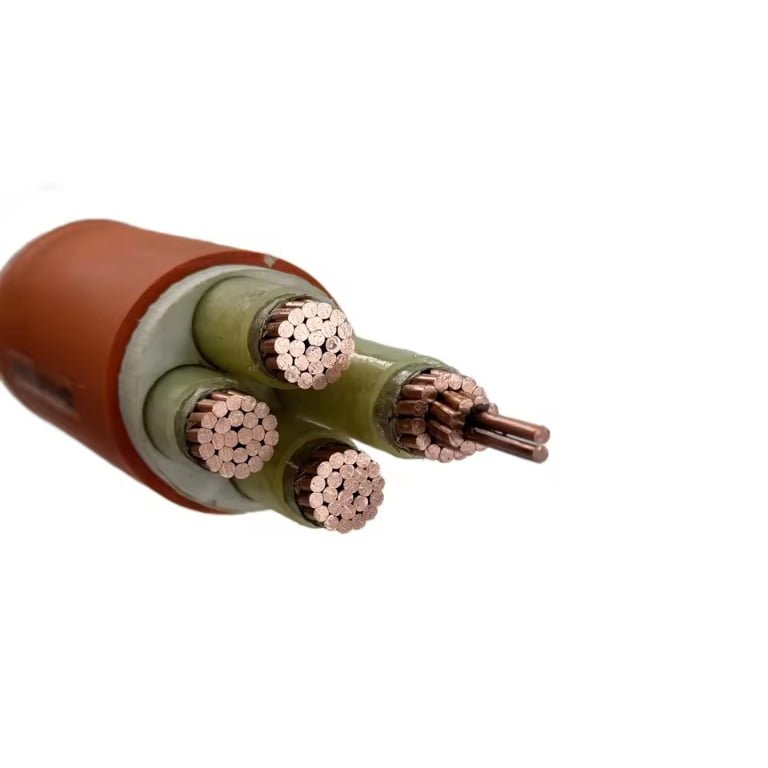
A cable wire is a current-carrying electrical conductor — either a single solid wire or an assembly of multiple stranded wires — insulated, protected, and configured to transmit power or signals between two points. The term encompasses everything from a simple 300/500 V PVC-insulated single core to a 500 kV extra-high-voltage transmission cable, distinguished by conductor material (typically copper or aluminum), insulation type, voltage class, and construction standard such as IEC 60228.
What makes this worth understanding in depth is that the global wire and cable market sits somewhere around USD 225 billion and is on a trajectory toward USD 300 billion or more by 2030 — which tells you the industry is not standing still. New insulation chemistries, revised installation standards, shifting conductor pricing, and the accelerating demand from renewable energy infrastructure are all changing what a “standard” cable specification actually looks like on the ground. The fundamentals, though — conductor physics, insulation ratings, construction classes — have not changed, and they are the part that actually determines whether a cable survives its service life or fails in year three.
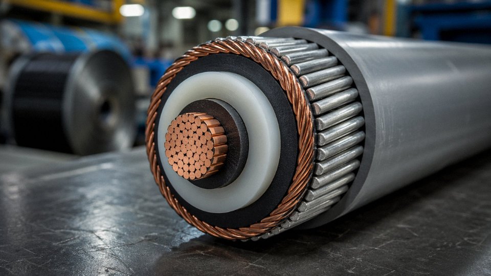
Anatomy of a Cable Wire: Every Layer Explained from Conductor to Outer Sheath
Understanding a cable’s cross-section is the fastest way to avoid expensive misspecification. Each concentric layer has a distinct mechanical or electrical job, and cutting corners on any one of them tends to show up as premature failure, not immediately, but six months into a commissioning cycle when you’re under pressure.
Conductor Core: Solid vs. Stranded, and Why It Matters for Real Installations
The conductor is where all the electrical work happens, and the construction choice has consequences that ripple through every layer above it.
Solid conductors (IEC 60228 Class 1) are cost-effective for fixed wiring in small cross-sections — typically up to 16 mm², sometimes 25 mm² in building wire. They’re stiffer, cheaper to manufacture, and marginally lower in DC resistance for a given cross-section. That said, they are not suitable anywhere the cable will flex repeatedly, because solid copper will work-harden and crack after relatively few bend cycles. In practice, I’ve seen Class 1 cable used in trunking installations where it never moves after pulling-in, and that’s fine. Use it in a control cabinet with moving doors and you’ll be replacing conductors within a year.
Stranded Class 2 is the dominant choice in power cable projects worldwide — IEC 60228 Class 2 resistance limits at 20 °C run from roughly 12.1 mΩ/m for 1.5 mm² copper down to about 0.0469 mΩ/m for 630 mm² copper, and the aluminum equivalents sit approximately 60% higher per the resistivity ratio (2.82 vs. 1.72 × 10⁻⁸ Ω·m). For flexible applications — trailing cables, drag chains, machine tools — Class 5 or Class 6 fine-wire stranding is essential. The finer the individual wire, the better the fatigue resistance under repeated flexing, though fine-stranded conductors require crimped or ferrule-terminated connections; twist them under a screw terminal and you’re asking for a hot joint.
Conductor Screen and Insulation Screen
In cables rated above roughly 3.6/6 kV, a thin semiconducting layer sits between conductor and insulation. Its job is to smooth out the highly non-uniform electric field that would otherwise concentrate around individual wires in a stranded conductor — sharp geometry creates field concentration, which creates partial discharge, which eventually destroys the insulation from the inside out. The same logic applies at the outer surface of the insulation: the insulation screen eliminates the air gap between insulation and metallic screen.
Omitting or damaging the conductor screen during jointing on MV cables is a leading cause of premature cable joint failure in the field.True
Partial discharge initiated at the conductor-insulation interface due to field irregularities is well-documented as a primary failure mechanism in medium-voltage cable joints where semiconducting layers are improperly cut back or contaminated.
This is also why MV cable jointing requires trained personnel and proper tooling — a nick in the semiconducting layer that goes unnoticed during installation can take two or three years to develop into a fault.
Insulation: The Performance-Cost Sliding Scale
PVC insulation is cheap, easy to process, and adequate up to 70 °C conductor temperature. For most 0.6/1 kV building and industrial wiring, it does the job. XLPE (cross-linked polyethylene) is the workhorse for anything more demanding: 90 °C continuous, 130 °C emergency overload, and 250 °C short-circuit withstand. Its dielectric strength runs in the range of 20–40 kV/mm depending on formulation and thickness, compared to PVC at roughly 10–30 kV/mm. Insulation wall thickness scales with voltage class — a 0.6/1 kV XLPE cable might carry 0.7 mm of insulation on a 1.5 mm² core, while a 12/20 kV design will typically see 5.5 mm or more on the same conductor size.
EPR (ethylene propylene rubber) is favored in marine, offshore, and mining environments because of its excellent flexibility at low temperatures and its resistance to moisture and ozone — it doesn’t embrittle the way PVC does below –15 °C or so. Silicone rubber goes further still, rated to 180 °C continuous, which is why you see it in furnace wiring, locomotive cabling, and applications where a burning-cable scenario requires the circuit to keep functioning for a defined period.
The cost staircase, roughly: PVC < XLPE < EPR < silicone rubber. Don’t over-specify if your ambient conditions don’t justify it, but don’t under-specify either. A PVC-insulated cable in a 55 °C cable duct in a hot climate is already operating near its rating limit before you factor in mutual heating from adjacent cables.
Metallic Screen Construction
Above 6 kV, a metallic screen over the insulation serves two functions: it provides a defined return path for fault current, and it shields the cable from external electric fields. Construction options include copper tape (overlapped or gapped), helically applied copper wires, or aluminum foil laminates. Screen cross-section must be sized to carry the prospective earth fault current for the fault clearance duration — a screen that can’t handle the let-through energy will burn off at the joint, which is a genuinely unpleasant event. For EMI-sensitive instrumentation cables at lower voltages, a copper foil or braided screen primarily handles shielding rather than fault capacity.
Fillers, Binders, and Bedding
These get almost no attention in specifications, but they earn their place. In a multicore cable, the spaces between round cores are filled — typically with polypropylene yarn, polyethylene strips, or similar materials — to maintain a circular overall cross-section. A non-circular cable armors unevenly, and uneven armouring means uneven mechanical protection. Bedding tape below the armour provides a smooth, damage-free surface so the armour wires don’t bite into the underlying layers under tensile load. Moisture-blocking fillers, used in direct-burial designs, prevent water from wicking along the cable length if the outer sheath is breached — a detail worth specifying explicitly on underground installations in high water-table areas.
Armouring: Matching the Type to the Installation
Steel wire armour (SWA) is the standard for direct burial and underground duct installations where tensile load and crush resistance both matter. Tensile load ratings depend heavily on wire diameter and layer configuration — a 4-core 95 mm² SWA cable might handle 15–25 kN axial pull, though the exact figure depends on manufacturer construction and the standard being applied.
Steel tape armour (STA) is lighter and cheaper but offers no meaningful tensile strength; it’s used for multicore cables in trays or ducts where mechanical protection from point loading is the concern rather than pull-in loads.
Aluminum wire armour (AWA) is the correct choice for single-core AC cables. Run single-core cables with steel armour and you create a magnetic circuit that generates circulating currents in the armour, producing additional losses and heat — on large conductors, this can be surprisingly significant. AWA avoids that problem. The trade-off is lower tensile strength than equivalent SWA and a higher material cost.
Outer Sheath: Fire Performance Is Not Optional in Many Applications
The outer sheath is the cable’s first line of defense against the environment. Standard PVC (ST1 grade) handles most general industrial and indoor applications, with acceptable oil and abrasion resistance. Harder ST2 compound improves abrasion resistance for rougher handling. Polyethylene (PE) is preferred for direct-burial outdoor applications given its better UV and moisture resistance compared to PVC.
LSZH (low smoke zero halogen) sheaths exist because burning PVC cables in confined spaces — tunnels, ships, data centers, rail vehicles — produce dense, toxic, corrosive smoke that kills people and destroys equipment. LSZH compounds have an oxygen index typically above 30 (versus roughly 23–25 for standard PVC), which means they are significantly harder to sustain in combustion. IEC 60332-1 and IEC 60332-3 govern flame propagation resistance; IEC 61034 measures smoke density; EN 50575 (the CPR standard in Europe) assigns performance classes from Eca through Aca. Specifying the right class matters for building regulations compliance and, in some jurisdictions, insurance coverage. Don’t accept “LSZH” as a description without asking which IEC 60332 test was passed and at what installation configuration — the difference between -1 and -3 is substantial.
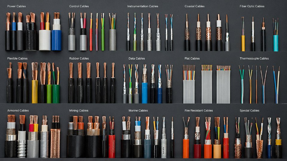
Cable Wire Types and Classification: A Practical Reference for Specifiers and Buyers
Getting the classification right before procurement starts saves real money. Mis-specifying a medium-voltage cable as low-voltage doesn’t just waste material — it creates a safety liability that won’t show up until something fails at 3 a.m. on a Monday. Here’s how experienced specifiers think through the decision tree.
Voltage Level: The First and Non-Negotiable Sort
Low-voltage cables (up to 1 kV) — NYY, NYYCY, N2XY and their variants — cover the vast majority of industrial and commercial distribution work. Construction is relatively straightforward: stranded copper or aluminum conductor, PVC or XLPE insulation, optional screen, armour, and an outer sheath. Cost per meter stays manageable.
Once you step into medium voltage (roughly 1 kV to 36 kV), construction jumps immediately: conductor screen, insulation screen, metallic screen, bedding, armour, oversheath — each layer engineered and tested. NA2XS2Y is the workhorse here for aluminum-conductor MV networks. The cost per meter roughly doubles or triples compared to an equivalent LV cable of the same conductor cross-section, depending on voltage grade and screen design.
High-voltage (36–150 kV) and extra-high-voltage (above 150 kV, up to 500 kV and beyond for HVDC systems) cables are a different engineering world entirely. Insulation eccentricity tolerances tighten severely, jointing requires factory-trained specialists, and lead times can stretch to 40–70 weeks for custom EHV designs. A procurement manager treating an EHV cable like a commodity order will learn a hard lesson about factory allocation windows.
Application Sector: Match the Cable to the Duty
Power distribution cables handle bulk energy transfer. Control and instrumentation cables (typically 0.5–2.5 mm² multi-core, individually screened) carry signals and low-power commands — using power cable here means you’re paying for copper you don’t need and likely injecting noise into instrumentation loops.
Fire-resistant cables (IEC 60331 / BS 6387 rated) maintain circuit integrity under direct flame — critical for emergency lighting, fire pump circuits, smoke extraction systems. Standard XLPE will fail these tests. The difference matters in building code compliance sign-off.
Marine cables, mining cables (trailing and reeling types), railway signaling cables, PV DC cables (rated for 1.5 kV DC, UV-resistant, often halogen-free), and wind farm inter-array cables (submarine or direct burial, typically 33 kV three-core) each carry specific mechanical, chemical, or certification requirements that a general-purpose cable won’t satisfy.
Copper vs. Aluminum: The Trade-Off Is Always Cost versus Space
Copper’s resistivity (1.72 × 10⁻⁸ Ω·m) versus aluminum’s (2.82 × 10⁻⁸ Ω·m) means copper carries roughly 40% more current per mm² of cross-section. In practice, you upsize aluminum by one to two standard cross-sections to match copper ampacity — which partially, but not fully, offsets aluminum’s lower cost per kg. Aluminum cables are meaningfully lighter, which matters for aerial installation and large cable ladder runs. Jointing aluminum requires oxide-inhibiting compound and correct compression tooling; skip either step and you get a high-resistance joint that overheats within months.
| Cross-section | Cu ampacity (free air, 30 °C) | Al ampacity (free air, 30 °C) | Notes |
|---|---|---|---|
| 50 mm² | ~215–240 A | ~165–185 A | Depends on insulation type, grouping |
| 95 mm² | ~290–330 A | ~225–255 A | XLPE-insulated single-core reference |
| 185 mm² | ~430–490 A | ~330–375 A | Trefoil or flat formation affects result |
| 300 mm² | ~570–640 A | ~440–500 A | Burial depth and soil resistivity shift these significantly |
A 95 mm² copper XLPE armored power cable can carry 250–300 A continuously in free air at 30 °C ambientTrue
This range aligns with IEC 60502-1 rated current tables for single-core and multi-core XLPE cables; actual value depends on installation method, grouping factor, and ambient temperature correction.
Reading a Cable Designation: IEC and National Standards
Standard designations look cryptic until you know the decoding key. Take N2XSY 3×95/16 mm² 12/20 kV:
- N — German VDE/IEC standard family (Normentyp)
- 2X — XLPE insulation
- S — copper wire screen
- Y — PVC outer sheath
- 3×95 — three cores, each 95 mm² conductor
- /16 — 16 mm² concentric screen cross-section
- 12/20 kV — rated voltage, conductor-to-screen / conductor-to-conductor
BS, UL, and GB designations follow similar logic but different letter codes. A GB/T 12706 designation uses entirely different prefixes — YJV, YJLV, ZR-YJV for flame-retardant variants — which causes genuine confusion during cross-border procurement if engineers assume IEC and GB cables are interchangeable without checking the underlying test standards. They usually aren’t, at least not without a conformity review.
Jinda’s product range spans this entire classification landscape: XLPE power cables from LV through MV, fire-resistant and flame-retardant control cables, special cables engineered for oil and gas environments (where chemical resistance and sometimes Ex-rated sheathing are mandatory), and marine cables built to IEC 60092 and classification society requirements. Supplying into 50-plus countries means the engineering and documentation team handles multi-standard compliance as routine work rather than a special project — that operational reality matters when you’re sourcing for a project that needs both IEC and local-standard certificates on the same delivery.
Key Electrical and Mechanical Performance Parameters Every Buyer Must Verify
A cable datasheet can run three pages and still leave out the numbers that actually matter on a project. Here is what to pull out of every submission before you issue a purchase order.
DC Resistance at 20 °C (Ω/km)
This is the single most telling number on a conductor quality check. IEC 60228 publishes maximum DC resistance limits for each conductor class and cross-section — for example, a 95 mm² Class 2 stranded copper conductor must not exceed 0.193 Ω/km at 20 °C. If a supplier’s datasheet shows a value noticeably above that limit, one of two things is happening: the conductor is undersized (drawn thinner than declared), or the copper purity is below the expected ~99.9% electrolytic grade. Either way, higher resistance means higher I²R losses and more heat in service.
A cable with DC resistance 10% above the IEC 60228 limit for its declared cross-section is, in effect, a smaller conductor than you ordered.True
DC resistance is inversely proportional to cross-sectional area and conductor conductivity. A higher-than-permitted resistance value is a direct indicator that effective conductor area or material purity is below specification, not a calibration artifact.
Always request the actual test value from the factory test report, not just a datasheet nominal. Cross-check it against the IEC 60228 table yourself — it takes about two minutes and catches most conductor substitution problems before the cable ships.
Current-Carrying Capacity (Ampacity)
Ampacity is not a fixed number; it is a condition-dependent calculation. IEC 60287 defines the standard reference conditions: buried direct in ground at 20 °C soil temperature with 1.0 K·m/W thermal resistivity, installed in free air at 30 °C ambient, or pulled through a duct. A 95 mm² XLPE armored cable that carries 250–300 A in free air might derate to roughly 190–230 A in a saturated soil trench, depending on burial depth and soil thermal resistivity — which varies seasonally in some climates.
Grouping derating compounds this fast. Six cables laid touching in a tray at 30 °C ambient can each carry only around 55–65% of their single-cable free-air rating. Miss that factor on a cable tray design and you are building in a thermal failure from day one.
Voltage Withstand and Partial Discharge
For LV cables (up to 1 kV), routine factory testing applies an AC voltage of 3.5 kV for 5 minutes — straightforward pass/fail. For MV XLPE cables, partial discharge (PD) testing matters far more than the withstand voltage alone. A PD extinction voltage test at 1.73 × U₀ — where U₀ is the rated phase-to-earth voltage — checks that internal voids or contamination in the insulation are not creating inception sites that will slowly erode the XLPE over years of service. A cable that passes a 50 Hz withstand test but shows measurable PD activity at operating voltage is not a safe MV cable; it is a slow failure in progress. Insist on PD test reports for any MV purchase, and the acceptable level is typically below 10 pC at 1.73 × U₀.
Insulation Resistance
XLPE insulation in good condition typically measures above 1,000 MΩ·km at 20 °C when tested with a megohmmeter at 500–1,000 V DC. Values significantly below that — say, 50–100 MΩ·km — suggest moisture ingress, manufacturing contamination, or degraded insulation. One practical caveat: insulation resistance drops roughly 50% for every 10–15 °C rise in temperature, so a test result taken on a cable drum sitting in a 45 °C yard in summer will read lower than the same drum at 20 °C in a warehouse. Normalize for temperature before drawing conclusions.
Short-Circuit Current Rating
The adiabatic heating equation I²t = k²S² governs whether your cable survives a fault. Here, I is fault current in amperes, t is fault clearance time in seconds, S is conductor cross-section in mm², and k is a material constant — roughly 226 for copper at 70 °C initial temperature (XLPE insulation) and around 148 for aluminum under the same conditions. If your protection relay clears a 20 kA fault in 0.5 seconds, a 95 mm² copper conductor handles that comfortably; the same fault on 35 mm² aluminum does not. Check this against your protection coordination study, not just the cable rating table.
Mechanical Parameters
Armored cables have a minimum bending radius — typically 12 to 15 times the overall cable diameter for steel wire armored (SWA) construction. Violate that during installation and you can crack the armor wires or deform the insulation, creating stress points that never fully recover. For vertical riser installations, tensile strength ratings matter; many specifiers overlook this until a cable pulls its own weight loose from a clamp inside a shaft. IEC 60227 and IEC 60245 cover crush and impact testing for flexible cables; for fixed-installation power cables, IEC 60502 is the relevant standard for LV/MV mechanical performance requirements.
Fire Performance Tier
EN 50575 and the Euroclass system (ranging from Eca — basic flame spread — up to B2ca, which covers flame spread, heat release, smoke production, droplets, and acidity) set mandatory minimum classifications for cables in the EU. For public buildings in most European jurisdictions, Cca-s1b,d1,a1 is commonly required. Offshore platforms and tunnels often mandate Cca or B2ca combined with IEC 60332-3 bundle burning performance. IEC 60332-1 is a single-cable vertical flame test; IEC 60332-3 tests a full bundle — a much harder test that some cables pass individually but fail in grouped installation. Know which test standard your project specification is actually calling for before you accept a factory test certificate.
Raw Materials and Manufacturing Process: How Quality Is Built In, Not Tested In
Final inspection catches defects. It does not create quality. Any procurement engineer who has dealt with a batch rejection six weeks into a project already knows this. The difference between a technically credible cable manufacturer and a commodity price-cutter usually shows up not in the finished test report but in what happened three steps earlier on the production floor.
Copper Rod: Where Conductor Resistance Is Decided
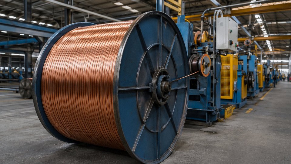
Everything starts with cathode copper purity. IEC 60028 sets the minimum at 99.95% Cu, and that threshold exists for a reason — impurities such as bismuth, antimony, or lead segregate at grain boundaries during drawing and cause wire breaks, which kills yield and quietly degrades conductivity. In practice, reputable rod suppliers certify purity at 99.97% or better, and the difference matters when you are drawing to fine diameters.
For standard power cable conductors, electrolytic tough-pitch (ETP) copper rod is the norm. For flexible cables — Class 5 and Class 6 per IEC 60228, the fine-stranded constructions used in welding cables, drag chains, and robotic arms — oxygen-free copper (OFC, typically C10100 or C10200 grade) is worth the premium. OFC has residual oxygen below roughly 5 ppm, which prevents hydrogen embrittlement and allows the wire to survive repeated flexing without developing microcracks. Specifying the wrong grade here is how you get a “flexible” cable that fatigues in under 100,000 flex cycles instead of surviving a million.
Wire Drawing and Stranding: Tolerance Is Not Optional
Multi-die continuous drawing reduces rod (typically 8 mm diameter) down to target conductor wire diameter through a series of tungsten carbide or polycrystalline diamond dies. For fine wire — anything below roughly 0.5 mm — diameter tolerance needs to sit at ±0.002 mm or tighter. Wider variation causes uneven current distribution in a stranded conductor and creates problems downstream in the stranding machine itself, where mismatched wire diameters produce a conductor that won’t compact cleanly.
Annealing temperature and time profile directly controls elongation. IEC 60228 Class 2 stranded conductors require a minimum 20% elongation at break; Class 5 and 6 require 30% or more. Under-annealing leaves the wire hard and brittle. Over-annealing softens it enough to cause handling problems and can slightly reduce tensile strength. Getting the profile right means controlling furnace temperature to within a few degrees across the full production run — not just at the start of a shift.
Planetary stranding controls lay length, which affects both the flexibility of the finished conductor and its DC resistance. A tighter lay increases resistance slightly; too loose and the cable won’t pass crush or bend tests. The governing relationship between lay length and conductor diameter is well understood, but it still requires active process control rather than set-and-forget.
Insulation Extrusion: The CCV Line Is Not All Equal
For XLPE-insulated medium- and high-voltage cables, the catenary continuous vulcanization (CCV) line is the production method of choice, and the performance gap between a well-controlled CCV line and a poorly controlled one is significant. Line speed, melt temperature profile across the three zones of the extruder head, nitrogen gas pressure inside the vulcanization tube, and — critically — degassing time all interact to determine void content in the cured insulation.
Voids matter because they are initiation sites for partial discharge. Even a void of a few tens of micrometers, at the right location in the insulation wall of a 33 kV cable, will initiate PD activity that erodes the insulation and eventually causes premature failure. This is not a theoretical concern; it is the reason IEC 60840 specifies PD testing at 1.5 U₀ for cables above 30 kV. Degassing — holding the finished cable core at elevated temperature (typically 60–70 °C) for 24 to 72 hours depending on insulation wall thickness — allows residual crosslinking byproducts to diffuse out before the cable is tested or installed. Skipping or shortening that step is a common cost-cutting move that shows up only months or years later in the field.
Triple-head extrusion (conductor screen, insulation, and insulation screen applied in one pass without the core being exposed to the atmosphere between layers) is the preferred configuration for MV and HV cables because it eliminates the contamination risk at the screen-insulation interface. Tandem lines that re-thread the core between layers introduce a step where airborne particles and moisture can contaminate a surface that will be inside a high-stress dielectric field for the next 30 years.
Screen, Tape Lapping, and Water Blocking
Copper tape screening requires a minimum overlap of 15% per IEC 60840. That overlap is not just a dimensional requirement — it is what maintains screen continuity across a cable bend radius. Semiconductor tape resistivity needs to sit in a defined window: low enough to grade the electric field at the insulation surface, but not so conductive that it causes losses. Swellable tape for longitudinal water blocking is worth including on any installation where the cable route passes through areas with groundwater risk; a single point of jacket damage in a flooded trench becomes a much smaller problem when the tape limits moisture ingress to a short cable section rather than allowing it to wick along the full run.
Armoring: Lay Angle Determines What the Cable Can Handle
Steel wire armour (SWA) applied by drum twisting or rigid stranding offers very different performance depending on lay angle. A shallower lay angle (more turns per meter) improves tensile performance — useful for vertical installations or submarine pulls. A steeper angle improves crush resistance and lateral stiffness. The zinc coating mass on the armour wires matters for corrosion resistance in aggressive soils; IEC 60227 Class A coating is the minimum for most buried applications, Class B for coastal or chemically active environments. Getting armour wire diameter tolerances wrong causes gaps in coverage and creates stress concentrations during bending.
Sheath Extrusion, Marking, and In-Process Quality Gates
Outer sheath compounds for outdoor installations need UV stabilizers — this sounds basic but it is frequently under-specified in project tender documents, and some suppliers respond to an unspecified sheath with whatever compound is cheapest on that day. Continuous laser printing of sequential meter markings, cable type, voltage rating, and manufacturer identification on the outer sheath is not just for compliance; it is how you trace a cable back to its production batch when a field issue shows up.
100% spark testing on insulation across the full production length, conductor resistance verification after stranding, and partial discharge testing on MV cores are standard in-process checkpoints at Jinda's facilities.True
These checks correspond to routine test requirements under IEC 60502-1, IEC 60502-2, and IEC 60840, and are verifiable via third-party test reports and factory audit.
The governing standards — IEC 60502 for low and medium voltage power cables, IEC 60840 for cables above 30 kV, and GB/T 12706 for the Chinese national equivalent — define routine tests that every manufactured length must pass, not just type-test samples. A supplier who cannot produce routine test certificates for a specific production batch is telling you something important about their process.
Vertical Integration Across Five Production Bases
Jinda operates five production bases across China covering roughly 470,000 m² of manufacturing space. The practical consequence of that scale is vertical integration from copper rod intake through to finished, tested, and marked cable on a dispatch reel. That matters for procurement engineers because batch-to-batch consistency — the thing that causes problems when you are installing 50 km of cable across 18 months of deliveries — is fundamentally a supply chain problem. Every external handoff between material suppliers is a point where a specification can quietly drift. Insulation compound from a different batch, rod from a different smelter, armour wire from a different coater: each is a variable. Controlling those variables internally, across a facilities footprint large enough to handle significant parallel production volumes, is how you reduce the probability of pulling cable from two delivery batches and finding that their DC resistance figures are not quite the same.
International Standards and Certifications: How to Read Compliance Documents Without Being Misled
Procurement engineers get burned here more often than anywhere else in the cable buying process. A supplier sends over a thick PDF of certificates, everything looks official, and the shipment arrives — only for the cable to fail an incoming inspection or, worse, a site audit after installation. Understanding what those documents actually prove, and what they don’t, is non-negotiable for any serious international project.
Type Tests, Routine Tests, and Sample Tests — Not the Same Thing
IEC 60502-1 and -2 draw a hard line between three categories of testing, and buyers need to respect that line.
Type tests (also called design approval tests) are the gold standard. They’re performed once on a representative cable construction to prove the design meets the standard — dielectric strength, insulation aging, conductor resistance, flame propagation, the works. When performed by an accredited third-party lab holding ILAC-MRA recognition, a type test report carries genuine international weight. The critical detail: type tests must be repeated whenever the design changes materially, and most standards bodies expect renewal roughly every five years even without a design change. A type test report from 2011 covering a cable with a different insulation thickness than what you’re ordering today is essentially worthless as compliance evidence for your project.
Routine tests happen at the factory on every drum or reel leaving production — conductor resistance, voltage withstand, spark testing on the line. They confirm batch consistency but don’t substitute for type approval.
Sample tests sit between the two: periodic checks on production samples, usually covering a subset of type test parameters. Useful for ongoing quality monitoring, but not a replacement for full third-party type testing.
The Regional Standards Map
IEC 60502 (medium voltage) and IEC 60840 (HV above 30 kV) are the baseline for most international projects, recognized across Asia, the Middle East, Africa, and large parts of Europe. BS 6724 and BS 7846 still dominate UK and Commonwealth infrastructure specifications — they’re broadly harmonized with IEC but differ on some armoring and sheath requirements, so don’t assume an IEC certificate covers a BS-specified project without checking. VDE 0276 is the German framework, widely accepted across Central Europe and in German-funded project financing. GB/T 12706 is the Chinese domestic equivalent; it’s technically close to IEC 60502 but not identical, and an international buyer should request IEC-certified product rather than accepting GB/T as equivalent unless the destination country explicitly accepts it.
For North America, UL 44 (thermoset-insulated) and UL 83 (thermoplastic) are the relevant marks — the UL Listed system is fundamentally different from IEC, involving ongoing production surveillance, not just a one-time test. Australian and New Zealand projects typically require AS/NZS 1125 compliance; this matters more than many Asian exporters realize, since the standards authority there does conduct market surveillance.
CE Marking Under EU CPR — Mandatory, Not Optional
Since July 2017, any cable permanently installed in EU construction works must carry a CE mark and a Declaration of Performance under the Construction Products Regulation. The EN 50575 classification system grades cables from Eca (lowest fire performance) through Dca, Cca, Bca, to Aca — and the class specified in a project’s fire safety design must match what’s installed. Supplying an Eca-classified cable into a project that calls for Cca-s1-d1-a1 is a compliance failure, full stop.
Since July 2017, cables permanently installed in EU construction works are legally required to carry a Declaration of Performance and CE mark under the EU Construction Products Regulation (EN 50575).True
This is confirmed by EU Regulation No 305/2011 (CPR) and the harmonized standard EN 50575:2014+A1:2016, which became mandatory for cables in the EU market from 1 July 2017.
Recognizing Legitimate Certification Bodies
CESI/KEMA, SGS, Bureau Veritas, TÜV Rheinland, and Intertek are the names you’ll see most on cable type test reports for international projects. DNV and Lloyd’s Register handle marine and offshore cable certification specifically — if you’re procuring for a vessel or offshore platform and the certificate isn’t from a recognized classification society, that’s a problem. Every reputable certification body maintains a public registry where certificate numbers can be verified. Use it. It takes five minutes and has caught fraudulent documents on more than a few incoming shipments.
Red Flags in Supplier Documentation
Watch for these specifically: test reports listing a conductor cross-section or voltage class that doesn’t match your purchase order; certificates bearing an accreditation logo but no ILAC-MRA endorsement (ILAC-MRA recognition is what gives a lab’s results mutual acceptance across member countries); and — probably the most common issue in practice — a certificate covering a product “family” where the family definition is vague enough to technically include anything the supplier wants it to cover. If you can’t map every parameter on the certificate directly to the cable being quoted, ask for a product-specific test report.
Traceability Documentation in Practice
For Jinda-supplied projects, full documentation typically includes ISO 9001-based quality management records, IEC-referenced type test reports from accredited laboratories, material certificates for copper or aluminum conductor and insulation compounds, routine test records for each production reel, and factory acceptance test (FAT) reports where contractually required. For large international orders — especially those involving EPC contractors or project financing — having that complete traceability package ready before shipment removes a major source of project delay. In my experience, the documentation review is where mid-tier suppliers lose contracts to technically comparable manufacturers who simply have better records systems.
How to Select the Right Cable Wire for Your Project: A Step-by-Step Engineering Decision Guide
Getting cable selection wrong is expensive in ways that aren’t always obvious upfront. An undersized conductor overheats and degrades insulation over months before it fails. The wrong sheath material in a wet trench corrodes armour wires quietly. A cable rated 0.6/1 kV installed on a 6.6 kV impedance-earthed system will fail catastrophically on the first earth fault. The sequence below follows the engineering logic — each step gates the next.
Step 1 — Define Voltage Class and System Earthing First
Everything else depends on this. You need U₀/U (phase-to-earth / phase-to-phase voltage) and the basic insulation level (BIL), but equally critical is how the system neutral is handled. A solidly earthed 11 kV network limits earth fault overvoltage to roughly 1.0 per unit; an unearthed or high-impedance earthed system of the same nominal voltage can sustain 1.73 per unit indefinitely on a healthy phase during a single earth fault. That distinction directly drives whether you need a conductor screen, how thick the insulation must be, and which IEC 60502 voltage designation applies. Specifying a 6/10 kV cable versus an 8.7/15 kV cable on paper looks like a minor label difference — the insulation wall thickness and material volume are meaningfully different, and so is the price. Get this wrong and no amount of derating correction downstream saves you.
Step 2 — Calculate Derated Ampacity, Not Nameplate Ampacity
A 95 mm² XLPE armoured cable rated 250–300 A in free air at 30 °C ambient might deliver only 180–210 A when buried in soil with thermal resistivity above 1.5 K·m/W, grouped with two other loaded circuits, in an ambient ground temperature of 35 °C. IEC 60287 provides the full methodology; in practice, apply the correction factors for soil resistivity, ambient temperature, and grouping in sequence, then select the next standard cross-section that comfortably clears the derated value with some margin — typically 10–15% headroom is prudent, particularly if the load profile will grow. Do not skip the grouping factor. Bundled cables in a crowded tray are one of the most common causes of premature insulation aging I’ve seen, and it’s entirely avoidable.
Step 3 — Check Voltage Drop, Especially on Long LV Runs
For low-voltage distribution, a cable that’s thermally adequate can still be the wrong size if the run is long. The simplified three-phase formula is:
ΔV = √3 × I × L × (R·cosφ + X·sinφ)
where L is one-way length in km, R and X are conductor resistance and reactance per km. IEC and BS 7671 both recommend keeping ΔV within 3–5% for most installations; motor starting and sensitive loads often require tighter limits. A 70 mm² copper cable on a 200 m, 400 V run feeding a 150 A load at 0.85 power factor will typically land close to the 3% boundary — check it, don’t assume.
Step 4 — Confirm Short-Circuit Withstand
The adiabatic equation — S = I_sc × √t / k — gives the minimum cross-section S (mm²) needed to survive a fault current I_sc (A) for clearing time t (seconds) without conductor damage. The factor k depends on conductor material and insulation type (115 for PVC/copper, 143 for XLPE/copper, roughly). If your upstream protection is slow — older fuses, oversized breakers — this check can push you up a cross-section size even after ampacity and voltage drop are satisfied. It’s a frequent oversight on retrofit projects where protection settings haven’t been revisited.
Step 5 — Match Mechanical Protection to the Installation Environment
Direct burial in soil or concrete requires armour (SWA or AWA) plus a polyethylene outer sheath rated for ground contact — bare SWA without an outer sheath corrodes within a few seasons in anything but dry neutral soil. Cable tray inside tunnels or plant buildings often mandates LSZH (low smoke zero halogen) sheathing where fire toxicity and visibility matter; this is increasingly a contractual requirement rather than a choice. Subsea and waterlogged duct runs need longitudinal water-blocking tape or gel-filled construction to prevent water treeing in the insulation over time. Moving machine applications — robotic arms, crane festoon systems, cable chains — require Class 5 or Class 6 flexible conductors with TPE or rubber insulation rated for repeated flexing; using a rigid Class 2 construction here will produce conductor wire breakage within months.
Step 6 — Apply Environment and Regulatory Overlays
Hazardous area installations in ATEX or IECEx Zones 1 and 2 require cables certified for those classifications — not just cables that happen to use similar materials. Offshore platforms under SOLAS must meet specific fire test standards (IEC 60332-3 category, typically); substituting a non-tested LSZH cable because the datasheet looks similar is a compliance failure waiting to surface during flag-state inspection. Solar farm DC wiring needs UV-resistant, double-insulated cables — PV1-F per IEC 62930 or USE-2 for North American projects — because standard building wire degrades quickly under prolonged UV exposure and elevated DC operating temperatures. These aren’t optional overlays; they’re scope-defining.
Step 7 — Confirm Standard Compliance and Procurement Reality
List the governing standard (IEC 60502-1 for MV, IEC 60227/60245 for LV flexible, EN 50525 for European market, etc.), request the relevant type test reports, and cross-check the test date and testing laboratory accreditation. A type test from 2009 on a product manufactured with a different compound today is not meaningful assurance.
Jinda maintains a stock program for common configurations and offers custom manufacturing for non-standard lengths, conductor cross-sections, and special sheath materials, with documented type test reports available for export markets.True
Large-volume manufacturers with integrated production typically carry buffer stock of high-runner configurations and can accommodate non-standard orders through the same production lines — Jinda's 470,000 m² multi-site operation supports this. Procurement teams should request lead time confirmation in writing against their project schedule milestone.
Confirm delivery lead time against your project schedule before finalising the specification — not after. Standard cross-sections in common configurations can ship in 2–6 weeks; non-standard constructions with special certifications can run 10–16 weeks depending on raw material availability and test queue time. Build that into the procurement plan early.
Installation, Handling, and Storage Best Practices That Protect Cable Wire Performance
Most cable failures I’ve seen in the field don’t trace back to a bad conductor or a substandard insulation batch. They trace back to something that happened between the factory gate and the moment of energization — a drum dropped on its side, a cable bent in freezing weather, a termination done by someone who’d watched a YouTube video once. Getting the product right is only half the job.
Drum Handling and Storage
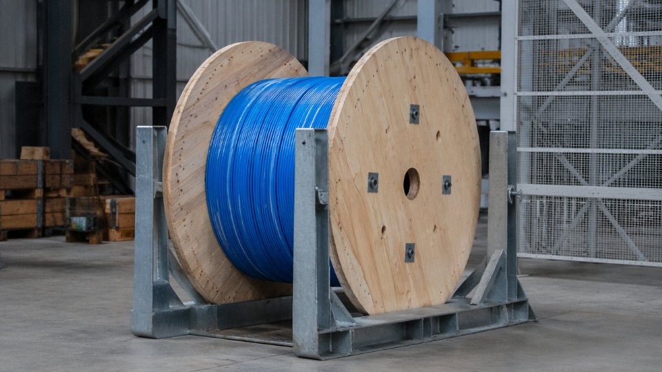
Store drums upright on their flanges. Always. A drum laid flat on its side concentrates the cable weight at one point on the coil, deforming the inner layers and, for larger cross-sections, permanently distorting the sheath geometry. Sit drums on timber bearers — never directly on bare concrete or soil — to keep moisture from wicking into the end seals. Those end caps or heat-shrink seals on the drum ends are your first line of defense against moisture ingress into the conductor interstices; check them on receipt and replace any that show damage.
Temperature matters in storage too. PVC-insulated cables stored below roughly -15 °C become brittle enough that uncoiling will crack the sheath — you may not see the crack, but water will find it. If a delivery arrives in winter and drums have been on a flatbed in sub-zero temperatures, give them 24 hours in a heated space before uncoiling or installing. XLPE-insulated cables are more tolerant, generally rated to -20 °C for static storage, but the same principle applies for handling.
Minimum Installation Temperature and Bending Limits
IEC 60502-1 is explicit about this: PVC cables must not be bent or installed below 0 °C without pre-warming the cable to above that threshold. The insulation compound loses ductility fast once you’re below freezing. XLPE cables are typically rated for installation down to -20 °C, though specific compounds vary — always check the manufacturer’s datasheet, not just the standard.
Bending radius is where I see the most casual disregard on site. The rule of thumb — 12× the overall cable diameter for unarmored cables, 15× for armored — exists because going tighter causes insulation deformation around the outer arc of the bend and conductor fatigue at the inner arc. The damage isn’t always visible. It shows up as an insulation failure six to eighteen months after commissioning, and by then the root cause is almost impossible to prove without a detailed failure investigation. Use a cable roller guide at every bend during pulling; it costs almost nothing compared to the fault.
Pulling Tension Limits
For copper conductors, the generally accepted maximum pulling tension is around 50 N/mm² of conductor cross-section; for aluminum, roughly 40 N/mm² — aluminum is lighter but yields at lower stress. So a 95 mm² copper cable can take up to about 4,750 N at the pulling grip, give or take depending on stranding class. During horizontal directional drilling (HDD) or long duct pulls, fit an inline dynamometer and log peak tension values. If you’re approaching the limit, slow down or add a secondary pull point; conductor strand separation from overpull is essentially irreversible.
Jointing, Termination, and End Sealing
The majority of MV cable failures occur at joints and terminations, not mid-span. This is well documented and largely preventable. Use heat-shrink or cold-shrink termination kits that are matched to your specific cable design — outer diameter, insulation type, and screen configuration all matter. A kit spec’d for a different cable geometry won’t maintain the correct field-grading geometry, and partial discharge begins immediately.
Jointing and termination work on MV cables should be performed only by personnel with documented, verifiable competence — not just general electrical experience.True
IEC 60502-4 and most utility network codes require jointers to hold recognized competency certification for the specific joint or termination system being installed. This is not bureaucratic formality; improper jointing is consistently the leading cause of MV cable service failures in statistical fault analysis.
Cut cable ends must be sealed with end caps or self-amalgamating tape immediately after cutting — within minutes on a humid site, not at the end of the day. XLPE insulation absorbs moisture through exposed cut ends, and water treeing accelerates insulation aging disproportionately; what starts as 0.1% moisture ingress can halve the effective service life of a cable over a decade of thermal cycling.
Post-Installation Testing
Before energizing any new MV cable circuit, run at minimum: an insulation resistance test at the appropriate DC voltage (typically 1–5 kV DC depending on cable rating), a continuity and phase rotation check, and a high-voltage withstand test. For XLPE cables specifically, avoid the old DC hi-pot method if you can — DC testing at high voltage can initiate space charge accumulation in XLPE that creates new defects rather than revealing existing ones. The current best practice, reflected in IEEE 400.2 and accepted by most utilities, is a very low frequency (VLF) test at 0.1 Hz, which stresses the insulation in a way that’s more representative of AC service without the space charge risk. The test equipment is more specialized but the cost of a misdiagnosed cable is far higher.
Frequently Asked Questions About Cable Wire
What is the difference between a cable and a wire?
A wire is a single conductor — one drawn metal element, bare or with a thin coating. A cable is an assembly: one or more insulated conductors, bundled with fillers, wrapped in bedding, and protected by a sheath or armour layer. In practice, the trade phrase “cable wire” refers to the complete manufactured product, conductor through outer jacket. The confusion matters in procurement because ordering “wire” when you need “cable” can leave you with unprotected conductors unsuitable for direct installation.
Is copper or aluminum better for power cables?
Depends heavily on the application. Copper’s resistivity (1.72 × 10⁻⁸ Ω·m) versus aluminum’s (2.82 × 10⁻⁸ Ω·m) means copper carries roughly 40% more current per mm² — for equal ampacity, aluminum needs approximately 1.6× the cross-section. That translates to heavier termination hardware and larger conduit. Aluminum is typically 60–70% cheaper per kilogram and dominates overhead transmission and large underground distribution runs where weight and material cost drive the decision. For industrial plants, commercial buildings, and anything flexible or frequently moved, copper wins on jointing reliability and fatigue life. A plant electrician will tell you that aluminum terminations that aren’t re-torqued on schedule are a fire risk. That’s not a materials problem — it’s a maintenance discipline problem — but in facilities with inconsistent maintenance practices, copper is simply safer to specify.
What does XLPE stand for and why is it preferred over PVC?
XLPE is cross-linked polyethylene. The cross-linking process — whether peroxide, silane, or electron beam — creates a three-dimensional polymer network that fundamentally changes the material’s behaviour under heat. Continuous operating temperature rises from 70 °C (PVC) to 90 °C; short-circuit rating reaches 250 °C. Dielectric strength improves, and there’s no plasticizer to migrate and embrittle the insulation over time the way PVC can after 15–20 years in a hot cable tray. Practically, an XLPE cable carries roughly 20–30% more current than a PVC cable of the same cross-section, which often means you can drop one conductor size and still meet ampacity — that saving compounds across a large project.
How do I verify a cable meets IEC 60502 without testing it myself?
Request the type test report from an ILAC-MRA accredited laboratory — KEMA, SGS, Bureau Veritas, and similar bodies issue these. The critical detail most buyers miss: confirm the certificate covers the exact design you’re ordering, meaning the conductor material, cross-section, insulation system, and voltage class must all match. A certificate for 16 mm² does not cover 95 mm². Type tests should be revalidated every five years or whenever there’s a material or design change. Ask for the routine test protocol for your specific production batch as well — type tests prove the design; routine tests prove your drums.
Jinda's IEC 60502 type test reports are issued by internationally accredited third-party laboratories and cover the specific cable designs available for order.True
Third-party accredited type testing is an auditable, verifiable process — buyers can request and independently verify test certificates against laboratory databases.
What is the minimum bending radius for armored cable?
For steel wire armored multi-core power cable, IEC 60502-1 recommends 12× the overall cable diameter during installation and 8× for the fixed installed bend. In practice, installers under schedule pressure sometimes force tighter bends around building corners. The insulation deforms, the armour wires buckle slightly, and you get a stress concentration point that may not fail immediately — it shows up as a partial discharge site two or three years later. Mark the minimum radius on your installation drawings and enforce it during supervision.
Can the same cable be used for both AC and DC systems?
Not reliably, especially above low voltage. In AC systems, the electric field in the insulation is capacitively distributed; in DC, it’s resistively distributed and the field profile reverses under load cycling. Standard XLPE cables designed and type-tested for AC should not be used for HVDC without a specific HVDC-rated design. For low-voltage DC applications — solar PV arrays being the most common case — use cables explicitly rated and marked for DC service, such as PV1-F or H1Z2Z2-K, which carry both the DC voltage rating and UV resistance appropriate for outdoor string runs.
How long does a quality XLPE power cable last in service?
IEC 60216 thermal endurance data and several decades of field experience point to a realistic design life of 30–40 years for correctly specified, installed, and operated XLPE medium-voltage cables. “Correctly” is doing a lot of work in that sentence. Sustained over-temperature, moisture ingress at unsealed terminations, partial discharge in under-sized insulation, and mechanical damage during installation all shorten life considerably — sometimes to under ten years. Regular partial discharge surveys and insulation resistance trending catch degradation early, before an unplanned outage makes the decision for you.
What certifications should I require when importing cable wire from China?
At minimum: ISO 9001 quality system certificate, IEC type test reports from an accredited laboratory, and compliance with the destination market’s mandatory standard — CE/CPR marking for EU, UL listing for the United States, AS/NZS certification for Australia. For marine or offshore projects, add DNV, Lloyd’s Register, or ABS type approval to that list. For large orders, a third-party pre-shipment inspection covering dimensional checks, conductor resistance, and insulation thickness is worth the modest cost. Self-declared compliance with no third-party verification is common among lower-tier suppliers and provides no real assurance.
Why Partnering with a Vertically Integrated Cable Manufacturer Reduces Total Project Risk
Most cable failures in the field don’t trace back to a design error. They trace back to a supply chain decision made under cost pressure — a trader who sourced conductors from one mill, insulation compound from a spot-market broker, and assembled the finished reel in a third facility with no unified quality record. By the time the installed cable fails a partial discharge test or trips a thermal relay eighteen months into service, the liability chain is a mess.
Vertical integration is the structural answer to that problem.
Material Traceability From Cathode to Reel
When a manufacturer controls copper rod drawing, stranding, extrusion, armoring, and sheathing inside a single quality system, every production lot carries a traceable thread from input cathode copper through to the finished drum label. That means a batch certificate isn’t a piece of paper assembled after the fact — it reflects actual in-process measurements at each stage. For a project engineer doing a factory acceptance test or a procurement manager responding to a customs authority asking for material origin documentation, the difference is substantial. Traders and cable assemblers structurally cannot provide this, regardless of how their datasheets are formatted.
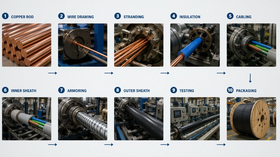
Batch-to-batch conductor resistance variation is a real problem on long cable runs. A 5–8% drift in resistivity across drum lots — not unusual when a trader is sourcing from multiple rod suppliers — can cause measurable current imbalance in three-phase systems and complicate protection relay settings. One quality system, one conductor specification, controlled at source.
Jinda controls the full production process from copper rod drawing through finished cable at its own manufacturing bases.True
Vertical integration across five production bases is a stated operational fact about Jinda's manufacturing model, not a marketing claim.
Capacity That Matches Infrastructure Project Timelines
A single-plant cable supplier is one maintenance shutdown, one flood, or one raw-material delay away from missing your commissioning date. Jinda’s five production bases covering 470,000 m² provide parallel manufacturing capacity that genuinely absorbs those risks — a critical factor when a project has contractual milestone penalties or a utility grid connection window that can’t slide by six weeks.
Large infrastructure projects — substations, industrial parks, port electrification, wind farm collection networks — routinely require 50,000–200,000 meters of cable delivered in phased batches tied to civil construction progress. That kind of schedule demands a supplier with real scheduling headroom, not one running a single extrusion line at 90% utilization.
Custom Engineering Without Long Lead Times
Standard catalog cables don’t fit every project. Unusual voltage ratings, dual-language drum marking for specific import markets, non-standard armor wire diameters for corrosive environments, bespoke sheath colors required by a national grid operator — these requests get refused or quoted at 20-week lead times by suppliers without in-house R&D and extrusion flexibility. A manufacturer with dedicated engineering staff and configurable tooling can typically turn around a custom design review in days, not months.
Technical Support Across the Full Project Lifecycle
Pre-project cable sizing, mid-project certification documentation for customs clearance, and post-installation fault diagnosis are not add-on services at Jinda — they’re functions that a 1,000-person organization with dedicated technical staff can actually deliver. Commodity suppliers quote price. A manufacturer with this depth quotes price and sends an engineer.
Stability You Can Build a Supply Agreement Around
Vertically integrated manufacturers can hedge copper exposure through forward purchasing and lock in compound supply contracts, then pass a portion of that stability to long-term customers as price predictability. Traders absorb no manufacturing risk — they pass all of it upstream to you.
Since 1987, Jinda has supplied customers across more than 50 countries, navigating everything from CE marking requirements to Gulf Cooperation Council approvals to project-specific factory audits. That accumulated documentation and logistics experience reduces onboarding risk for new international partners in a way that a newer or smaller supplier simply can’t replicate.
Submit your project specifications for a technical review and quotation. Jinda commits to a 24-hour initial response, and sample cables for pre-qualification testing are available on request.