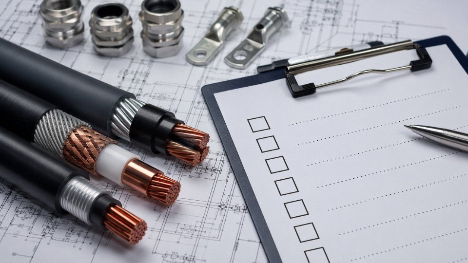
Specifying the wrong cable voltage class is one of those mistakes that tends to announce itself at the worst possible time — during commissioning, under load, or after a fault that takes out a transformer bay and three shifts of production with it. Under-insulated cable run at HT voltages will break down, sometimes gradually through partial discharge, sometimes all at once. Either way, the rework costs, the unplanned downtime, and the potential equipment damage dwarf whatever was saved on the original purchase. Getting the HT/LT distinction right at the specification stage is the only point in the project where it costs nothing.
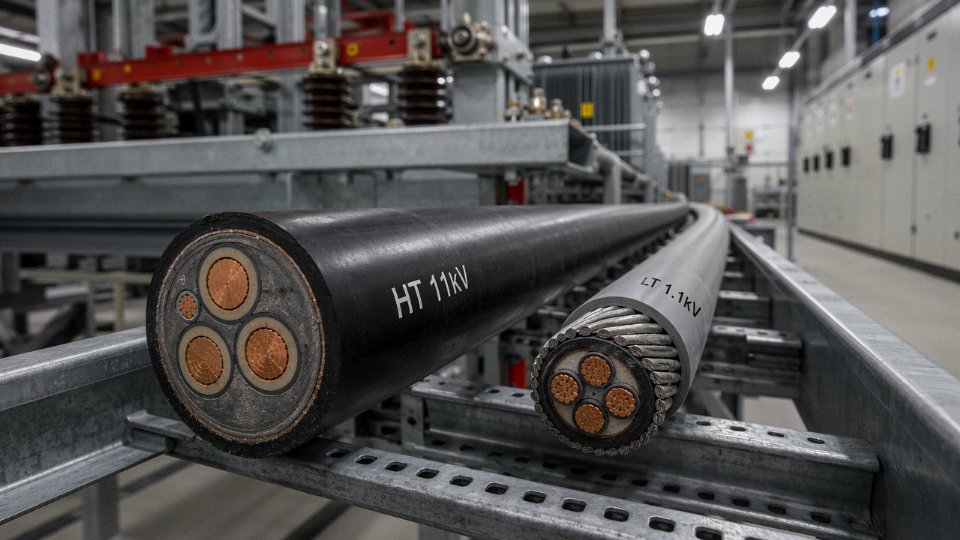
HT (High Tension) cables are rated for voltages typically from 3.3 kV up to 33 kV and above, used for primary distribution networks, substations, and large industrial feeders. LT (Low Tension) cables are rated up to 1.1 kV and cover the vast majority of end-use wiring inside buildings, machinery, and secondary distribution panels. The core difference is insulation thickness and dielectric design — HT cables carry insulation ranging from roughly 3.4 mm to 8.0 mm depending on voltage class, while LT cables run 0.6–2.0 mm.
What makes this more than a simple voltage lookup is how procurement decisions, installation environments, and fault consequences diverge once you cross that 1.1 kV line. The engineering requirements, the standards, the jointing skills, and the long-term failure modes are genuinely different categories — not just a matter of more of the same.
Construction Layers of LT Cable: Conductor, Insulation, Bedding, Armour, and Sheath Explained Layer by Layer
Understanding what sits inside an LT cable — and why each layer exists — separates engineers who can interrogate a datasheet from those who just approve one. Every layer has a job. When one is under-specified, the failure usually shows up somewhere else, and by then it’s rarely cheap to fix.
Conductor: Copper or Aluminium, Solid or Stranded
The conductor is where the argument usually starts in procurement. Annealed copper remains the default for most industrial LT installations — plain or tinned, available as solid (Class 1), stranded (Class 2), or flexible (Class 5) per IEC 60228. Cross-sections run from 1.5 mm² for control wiring up to 630 mm² for main feeders, though in practice anything above 300 mm² in copper tends to trigger a serious look at aluminium on cost grounds alone. Aluminium conductors, typically Class 2 stranded, carry roughly 20–25% less current for the same cross-section, which means you upsize — a 95 mm² copper circuit often becomes 150 mm² aluminium — but the weight saving is real and the material cost gap can be decisive on long cable runs. Termination is where aluminium bites back: bi-metallic lugs, anti-oxidant compound, and torque-controlled jointing are non-negotiable, not optional. Skip any of those and you’re looking at a high-resistance joint that runs hot and fails quietly until it doesn’t.
Insulation: PVC, XLPE, and EPR Side by Side
PVC insulation handles up to 70°C continuous conductor temperature in older designs, though compound improvements push some grades to 90°C. It’s cheap, flexible, and well understood, but it ages under sustained heat and loses plasticiser over time — cables in hot plant rooms can go brittle within 15–20 years. XLPE is cross-linked, which means it holds its shape and dielectric properties at 90°C continuous and survives up to 250°C during a short-circuit event. Dielectric strength for XLPE typically runs 20–25 kV/mm depending on the compound and test method, compared to roughly 15–20 kV/mm for standard PVC. EPR (ethylene propylene rubber) sits between the two in cost, offers better flexibility at low temperatures, and is the usual choice for mining cables and marine applications where the cable gets physically abused rather than just thermally stressed.
Core Identification: Colour, Numbers, and Stripes
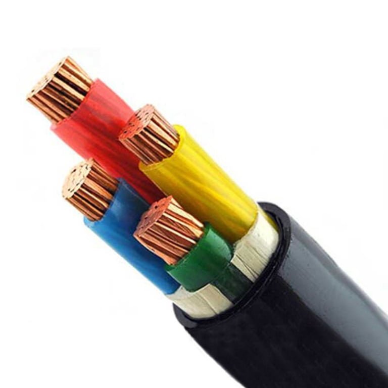
Multi-core LT cables follow IEC 60446 for colour coding — brown, black, grey, blue for a 4-core, with green/yellow reserved strictly for protective earth. Above 5 cores, numbered cores (printed or embossed) become standard, running up to 37 cores in instrumentation or control cables. Striped identification appears on some manufacturers’ designs for intermediate core counts. Getting this wrong on site causes misidentification during jointing, and a swapped neutral or earth on a 3-phase LT circuit has obvious consequences.
Bedding and Fillers
The inner sheath — PVC or PE — wraps around the laid-up cores before armour is applied. It’s not glamorous, but it does two things: it excludes moisture from migrating along the core interstices, and it provides a mechanically smooth surface so armour wires bed down evenly rather than cutting into insulation during bending or pulling. Fillers (PP string or similar) pack the spaces between cores to give the cable a round cross-section. A poorly filled cable distorts under armour tension and can crack insulation at the lay point over years of thermal cycling.
Armour: SWA, DWA, and STA — Choosing Correctly Matters
Single-wire armour (SWA) uses galvanised steel wires laid helically and handles direct burial, duct installation, and most overhead tray work. It provides good tensile strength and serves as an earth return path. Double-wire armour (DWA) adds a second layer of wires contra-wound — the weight penalty is real (roughly 15–25% heavier than SWA for the same core size), but it’s specified where the cable must resist high longitudinal tension, such as vertical risers in buildings or subsea-adjacent installations. Steel tape armour (STA) uses overlapping steel tapes rather than wires; it offers crush resistance but virtually no tensile strength, making it appropriate for duct-laid cables that won’t be pulled under load. Using STA where SWA was needed is a common and avoidable spec error.
Outer Sheath Compounds
Standard PVC outer sheaths (ST1, ST2 per IEC 60502) cover most industrial and utility applications. In confined or occupied spaces — substations, tunnels, hospitals, ships — LSZH (low-smoke zero-halogen) compounds are specified to limit toxic gas and smoke density during a fire event. UV-stabilised polyethylene is the right call for direct burial or aerial installation where the cable sees sustained sunlight; standard PVC chalks and cracks within a few years of UV exposure, and replacing a direct-buried cable because the sheath failed is an expensive lesson.
Worked Reference: 4-Core 95 mm² XLPE SWA LT Cable
A typical 4-core 95 mm² stranded copper XLPE insulated SWA PVC sheathed cable to IEC 60502-1 will have a finished outer diameter in the range of 48–54 mm depending on manufacturer tolerances and filler geometry. Weight runs roughly 4.8–5.5 kg/m. Current rating in free air is typically 220–245 A (depending on ambient temperature, grouping, and installation method per IEC 60364-5-52). These figures should be verified against the supplier’s specific datasheet — published ratings can vary by 5–10% between manufacturers using different compound densities and conductor compaction.
XLPE-insulated LT cables can withstand short-circuit conductor temperatures up to 250°C without permanent insulation damage.True
Cross-linked polyethylene's thermosetting structure resists deformation at elevated temperatures; IEC 60502 and cable design standards confirm 250°C as the maximum permitted short-circuit temperature for XLPE insulation, versus 160°C for standard PVC.
Construction Layers of HT Cable: How Screening, Insulation Thickness, and Metallic Sheath Design Change at Higher Voltages
Strip back an 11 kV cable next to a 1 kV LT cable and the difference is immediately obvious — not just the extra bulk, but layers that simply don’t exist in low-voltage construction. Each one addresses a failure mode that either doesn’t occur at LT voltages or occurs at a scale that’s manageable without dedicated engineering.
Conductor Screen: The First Semi-Conducting Layer
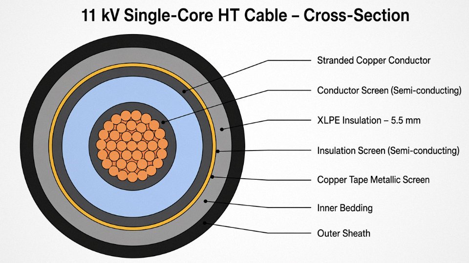
At elevated voltage, the electric field stress at the conductor surface becomes intense enough to ionise air trapped in microscopic voids between strands and the insulation wall. That ionisation — partial discharge — erodes XLPE from the inside, invisibly, until the cable fails. The conductor screen, an extruded semi-conducting compound applied directly over the conductor, eliminates those voids by providing a smooth, uniform surface at conductor potential.
This layer is typically co-extruded simultaneously with the main insulation in a triple-head process. That’s not a minor process detail — cables where these layers are applied in separate passes are considered inferior by most serious specifiers, because even a short exposure window between extrusion stages can allow surface contamination that seeds partial discharge sites later.
Main Insulation: XLPE Thickness by Voltage Class
XLPE has effectively replaced paper-oil and EPR for most modern HT cable applications. It handles operating temperatures up to 90 °C continuously (130 °C under emergency rating), it’s dry, and it’s mechanically tougher to handle during installation. Insulation thickness scales with voltage class per IEC 60502-2 — roughly 3.4 mm at 3.3 kV, around 4.5 mm at 6.6 kV, 5.5 mm at 11 kV, approximately 6.8 mm at 22 kV, and up to 8.0 mm at 33 kV. These figures assume a standard conductor size; actual thickness also depends on conductor diameter and the voltage ratio (Uo/U) specified for the network’s earthing regime.
Insulation Screen: The Outer Semi-Conducting Layer
Symmetrically, the outer surface of the insulation carries a second semi-conducting layer — same principle, opposite interface. It must bond intimately with the insulation during service but strip cleanly during jointing. That strippability matters enormously on site; a layer that tears ragged or leaves residue makes achieving a reliable joint geometry nearly impossible under field conditions. Installers working with poor-quality cable in a wet trench at midnight will tell you this is not a theoretical concern.
Metallic Screen: Sizing for Earth Fault, Not Just Field Control
Over the insulation screen sits the metallic screen, which serves two functions: it grounds the capacitive field and it carries earth fault current back to the source. Common constructions use helically applied copper tape, copper wire, or aluminium foil with a drain wire. Screen cross-section — typically somewhere between 16 mm² and 95 mm², depending on network fault level and fault clearance time — directly affects cable weight and cost. Oversizing it “for safety” is wasteful; undersizing it is dangerous. For single-core cables in trefoil, screen circulating currents and induced voltages need to be calculated explicitly, and cross-bonding or solid-bonding schemes specified before procurement.
Metallic screen cross-section in HT cables must be sized to carry the prospective earth fault current for the full fault clearance duration of upstream protection.True
IEC 60502-2 and network operator standards require the screen to survive the thermal stress of fault current (I²t) without damage. Undersized screens fail during earth faults, leaving the cable without ground reference and creating a safety hazard.
Water Blocking: Longitudinal and Radial Systems
Moisture ingress along the cable axis is a specific and serious failure mode in direct-buried HT installations. Water that enters through a sheath nick travels axially by capillary action through any unfilled spaces in the conductor stranding or between tape laps, eventually reaching a joint or termination — sometimes tens of metres from the original damage point. Swellable water-blocking tapes between layers and water-blocking compound (usually a gel or petroleum-based fill) in the conductor stranding address the longitudinal path. Radial moisture barriers — the sheath itself — handle the transverse path.
Moisture Barrier Sheath Options: A Practical Comparison
Three constructions dominate: lead alloy sheath, corrugated aluminium sheath, and PE-laminated aluminium tape (sometimes called an “AL/PE laminate” or “moisture barrier tape” sheath). Lead gives outstanding radial moisture resistance and flexibility for bending-intensive routes, but adds significant weight — a 33 kV three-core lead-sheathed cable can run 8–12 kg/m or more — and jointing requires skilled plumbers. Corrugated aluminium is lighter and more common in modern medium-voltage designs, though the corrugations must be carefully handled at joints to avoid cracking. The AL/PE laminate is the lightest option, used where moisture exposure risk is moderate and weight matters; it doesn’t perform as well as the others in sustained submersion.
Armour and Sheath: Screen Continuity Complications
The outer armour — SWA, DSTA, or STA depending on application — functions similarly to LT cable, but single-core HT cables introduce a complication. Steel wire armour forms a magnetic circuit around a single conductor, inducing circulating currents that cause heating and efficiency loss. Single-core HT cables therefore typically use aluminium wire armour (AWA) or aluminium tape armour to avoid this. Screen earthing continuity through the armour termination must also be managed deliberately; assume nothing is bonded correctly until you’ve verified it.
Key Electrical Parameters: How to Read and Compare HT and LT Cable Datasheets for Voltage, Current, and Fault Ratings
Rated Voltage Notation: U0/U and Um
Every cable datasheet carries a voltage designation in the form U0/U, and misreading it is one of the more common — and costly — specification errors on site. U0 is the rated voltage between any conductor and earth (or the metallic screen); U is the rated voltage conductor-to-conductor. So a 0.6/1 kV LT cable is designed for phase-to-earth stress of 600 V and phase-to-phase of 1,000 V — which is exactly what you get on a standard 400 V three-phase system with a solidly earthed neutral. For HT, a 6.35/11 kV cable matches an 11 kV distribution network: 6.35 kV phase-to-earth, 11 kV line-to-line.
Um is the maximum system voltage the cable can tolerate continuously — typically 10–15% above U. For the 6.35/11 kV example, Um is usually 12 kV. If your network runs with occasional voltage excursions above nominal (common in rural feeders), you need Um to cover the worst case, not just the nameplate system voltage. Selecting a cable where Um sits right at your normal operating ceiling leaves no margin for the system swings that happen in practice.
Current-Carrying Capacity (Ampacity)
Ampacity is not a single number — it is a function of at least five variables simultaneously. Conductor cross-section and material set the baseline; a 95 mm² copper XLPE cable in free air might carry roughly 270–310 A depending on the specific arrangement, whereas the same cable direct-buried in soil with thermal resistivity around 1.0 K·m/W drops to perhaps 210–250 A. Lay it in trefoil touching rather than flat-spaced, and you lose another 10–15% due to mutual heating.
IEC 60287 gives the calculation framework — it accounts for conductor resistance, dielectric losses (significant for HT), armour losses, and thermal resistances through each layer to the ambient. For HT cables operating above roughly 6 kV, dielectric losses are not negligible and must be included; ignoring them can lead to a cable that runs hotter than predicted, slowly degrading insulation long before the design life is up. Always request the ampacity table with the specific installation conditions stated, not a generic air-temperature figure.
Ambient temperature matters more than many procurement teams realise. A cable rated at 40°C ambient loses meaningful capacity if the duct bank runs through a boiler room or equatorial ground where soil temperature hits 30°C in summer. Derating factors in IEC 60287 tables handle this, but someone has to apply them.
Voltage Drop for LT Cables on Long Runs
For LT cables, voltage drop over long feeders is often the binding constraint — not thermal capacity. The standard approximation:
ΔV = √3 × I × L × (R·cosφ + X·sinφ)
where I is load current, L is route length in km, R and X are conductor resistance and reactance per km.
A worked example: 4-core 50 mm² copper XLPE, 100 m run, 400 A load, power factor 0.85. R ≈ 0.387 Ω/km, X ≈ 0.0823 Ω/km at 50 Hz. Plugging in gives ΔV roughly 28–30 V phase-to-phase, or around 7% of 400 V. That exceeds the 5% limit most industrial standards permit for motor loads. The correct fix here is usually to upsize the conductor — jumping to 95 mm² brings the drop to a more acceptable range — not to increase supply voltage.
Short-Circuit Current Rating
The adiabatic equation governs how much fault energy a conductor can absorb before the temperature limit is reached:
I²t = k²S²
where S is cross-section in mm², t is fault clearance time in seconds, and k is a material constant — for copper XLPE conductors the maximum conductor temperature under fault is 160°C (per IEC 60502), giving k ≈ 143 A·s½/mm². If your upstream protection clears a fault in 0.2 s and the available fault level is 25 kA, the minimum conductor size works out to roughly 78 mm² — meaning a 70 mm² cable that might be thermally adequate for normal load would not survive the fault. This check is separate from ampacity and is frequently skipped during early design.
XLPE cable conductors are rated to withstand a maximum temperature of 160°C during short-circuit conditions per IEC 60502 series standards.True
IEC 60502-1 and IEC 60502-2 specify 160°C as the maximum permissible conductor temperature during short-circuit for XLPE-insulated cables, distinguishing it from the 90°C continuous operating limit and the 250°C limit for PVC-insulated equivalents.
Capacitance and Charging Current in HT Cables
Underground HT cables have significantly higher capacitance than overhead lines — typically in the range of 0.2–0.4 µF/km for 11 kV XLPE cables depending on conductor size and insulation thickness. This generates capacitive charging current even at no load, and on long underground circuits it can reach values that meaningfully affect reactive power balance and even exceed the cable’s thermal rating before any real load is connected. Beyond a critical length — which varies but might be 20–40 km for 11 kV systems — the charging current alone consumes enough of the ampacity that the cable cannot deliver full rated load power. HT cable procurement for underground distribution should always include a capacitance specification and a check against the circuit’s reactive compensation strategy.
Insulation Resistance and Partial Discharge Testing
Routine factory tests for LT cables per IEC 60502-1 typically require a voltage withstand at 2.5U0 for 5 minutes — for a 0.6/1 kV cable that means 2.5 kV applied between conductor and screen. For HT cables under IEC 60502-2, type tests include partial discharge measurement at elevated voltage; partial discharge limits are usually stated in picocoulombs (pC) at a specified test voltage, and any sustained PD activity above the threshold indicates voids or contamination in the insulation that will eventually cause failure. When reviewing factory test reports, insist on the actual PD values measured, not just a pass/fail stamp.
Earth Fault Loop Impedance and Screen Sizing
HT cable metallic screens serve a dual purpose: they control the electric field gradient, and they must carry earth fault current long enough for protection to operate. Screen cross-section sizing follows the same adiabatic logic as conductor sizing — the screen must not overheat before the relay clears the fault. In practice, a poorly sized screen on a 33 kV cable in a network with slow earth fault protection can reach temperatures that weld the screen to the insulation or the bedding, causing collateral damage well beyond the original fault. Specifying screen size requires knowing the maximum earth fault current at the cable location and the protection operating time — neither of which appears on the standard datasheet, so the engineer has to bring both pieces together.
Installation Methods, Jointing, and Termination: Where LT and HT Cables Require Completely Different Site Practices
The voltage class of a cable doesn’t just determine what insulation thickness goes inside the factory — it dictates almost everything that happens on site, from how you unroll the drum to how long commissioning takes. Getting this wrong on an HT circuit costs far more than getting it wrong on an LT one. A mis-terminated 415 V joint might cause a fault. A mis-terminated 11 kV joint will usually cause an explosion.
Bending Radius and Drum Positioning
LT multi-core SWA cables generally require a minimum bending radius of 8–12× the overall cable diameter, depending on conductor cross-section and whether the cable is armoured. That’s manageable with standard cable rollers and a reasonably clear trench run. Single-core HT cables are a different problem: minimum bending radii typically run 15–20× overall diameter, which on a large 630 mm² 11 kV single-core cable can mean a bend radius approaching 800–900 mm. Ignore that figure and you risk deforming the XLPE insulation screen interface — a defect that won’t show up on a basic insulation resistance test but will initiate partial discharge and fail the cable within a few years of service.
Drum positioning matters before you even start pulling. For HT single-core cables, the drum stand needs to be set far enough back from the first duct bend that the cable enters the bend gradually. Pulling tension limits for HT cables are typically calculated from the conductor cross-section (roughly 50–70 N/mm² on copper conductors, depending on stranding), and sidewall pressure limits at bends are usually in the range of 3,000–5,000 N/m — figures your pulling contractor should be calculating, not guessing. Use only lubricants specifically approved for XLPE and LSZH sheaths; soap-based compounds or petroleum-based products can attack the sheath or contaminate the insulation surface at joints.
Trench Depth, Bedding, and Protection
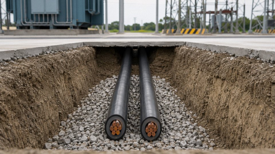
Most national installation codes require LT direct-buried cables at around 0.6 m depth, with HT cables typically at 0.9–1.2 m, though the exact requirement depends on the local standard and the land use above the route. The bedding sand underneath and around a direct-buried HT cable should be clean, stone-free, and compacted in layers — this isn’t a detail to leave to the groundworks subcontractor without explicit specification. Marker tape goes in at around 300 mm below finished surface level, and concrete marker posts at regular intervals are standard practice on HT routes, particularly at changes of direction.
LT Jointing: Practical Reality
Straight-through and tee joints on LT cables using heat-shrink or cold-shrink kits are routine work for a competent electrician. A typical LT heat-shrink straight joint on a 4-core 95 mm² SWA cable takes an experienced jointer perhaps 1.5–3 hours, depending on site conditions. Cold-shrink kits are faster in cold weather and arguably more consistent for less experienced teams since you don’t depend on flame technique.
HT Jointing: Where Discipline Actually Matters
At 11 kV and above, jointing is a different discipline. The semi-conducting screen on each cable end must be stripped to a precise, clean boundary — the geometry of the stress cone depends on it. Any nick in the XLPE insulation surface, any contamination, any variation in the screen cut length can create a field enhancement point that will fail under impulse conditions.
Factory-made pre-moulded cold-shrink joints are generally preferred over site-assembled heat-shrink for 11 kV and above. The reason is simple: pre-moulded geometry is controlled at the factory under clean conditions. Site heat-shrink requires the jointer to build up the stress relief geometry layer by layer, and the margin for error is narrow.
Pre-moulded cold-shrink HT joints are less dependent on site conditions and jointer experience than multi-layer heat-shrink assemblies at 11 kV and above.True
Pre-moulded joints have factory-controlled stress cone geometry that does not rely on correct sequencing of heat-shrink layers or flame technique on site. IEC 60502-4 type-test requirements confirm joint designs, but field failure data consistently shows higher failure rates in poorly executed heat-shrink joints at medium voltage.
HT Terminations: Indoor vs. Outdoor
Indoor HT terminations use a stress cone and a deflector to redistribute the electric field at the screen cut, and they’re typically housed in a switchgear cubicle with limited exposure to contamination. Outdoor terminations require weathershed insulators with sufficient creepage distance for the pollution severity class of the site — IEC 60815 defines four classes, and a coastal or industrial site can push you from a standard creepage distance of roughly 16 mm/kV up to 25 mm/kV or higher. Specifying the wrong termination for a coastal substation is a common procurement error that only becomes visible after a few years of salt-fog exposure.
Screen Bonding on Single-Core HT Cables
Single-core HT cables carry a metallic screen that will have voltage induced into it by the cable’s own magnetic field. How you bond that screen affects both safety and losses.
| Bonding Strategy | Typical Application | Induced Voltage Risk | Circulating Current Loss |
|---|---|---|---|
| Solid bonding (both ends) | Short runs, simple earthing | Low | Moderate to high |
| Single-point bonding | Medium runs, screen voltage < 65 V (IEC limit) | Managed with sheath voltage limiters | Negligible |
| Cross-bonding | Long HV/EHV cable routes in multiple minor sections | Balanced, low net voltage | Very low |
The 65 V limit on screen-to-earth voltage under normal operating conditions (per IEC 60949 and related standards) is what usually forces the choice between single-point and cross-bonding. On a short 11 kV feeder of 200 m or less, solid bonding is often simplest. On a longer 33 kV run, single-point bonding with properly rated sheath voltage limiters is typical. Cross-bonding becomes worth the installation complexity only on routes long enough to be divided into at least three roughly equal minor sections — usually anything beyond 1–1.5 km at 33 kV, though the actual calculation depends on conductor size and load current.
In practice, screen bonding design is often left too late in a project, then rushed at installation. The consequence is either unnecessary circulating current losses running for the cable’s entire service life, or sheath overvoltages that damage the outer jacket and create a safety hazard. Neither is acceptable on a circuit rated to run for 30–40 years.
Standards, Testing, and Certification Landscape: IEC, BS, IS, and NEC Compliance for HT and LT Cable Procurement
Specifying “IEC-compliant cable” on a purchase order means almost nothing without the specific standard number, part, and voltage designation. Procurement managers who skip that detail routinely receive test reports that look credible but cover a different voltage class or omit tests that actually matter for the application. Here is what you need to pin down.
IEC 60502: Two Parts, Two Very Different Test Regimes
IEC 60502-1 covers extruded solid dielectric cables rated from 1 kV up to 3 kV — essentially the upper end of the LT range and the transition zone. Routine tests (run on every drum) include conductor resistance verification, a high-voltage withstand test, and a check on insulation resistance. Sample tests, pulled periodically from production batches, add insulation thickness measurement and mechanical checks. Type tests, done once to qualify a design, include bending, tensile load, and thermal ageing sequences. For most LT procurement, this is the document your supplier’s test report should reference explicitly, with the test voltage and pass/fail results shown per clause.
IEC 60502-2 is a different animal. It applies to HT cables from 6 kV through 30 kV, and it introduces tests that have no equivalent in Part 1. The partial discharge test requires that discharge magnitude stays below 10 pC at 1.73U₀ — and that figure is non-negotiable, because partial discharge in an HT cable is the early mechanism of insulation treeing that eventually causes catastrophic failure. The tan delta (loss angle) measurement tells you about insulation quality in a way that a simple withstand test cannot. Water penetration testing applies only to longitudinally water-blocked designs, but if you’re specifying a direct-buried HT cable in a region with high water table or seasonal flooding, you should be insisting on this test and checking that the blocking compound is actually present — not just listed on the drawing.
Conductor Classes Under IEC 60228
IEC 60228 defines conductor classes 1 through 6, and the class you specify directly affects three things: flexibility during installation, the DC resistance value used in your ampacity calculation, and the price. Class 1 (solid) and Class 2 (stranded) are the standard choices for fixed power installations. Classes 5 and 6 are flexible — appropriate for trailing cables or frequent flexing, but they cost more and carry slightly higher resistance per unit length, which matters when you’re sizing long LT feeder runs. Suppliers sometimes offer a Class 2 conductor but quote resistance to Class 1 tolerances on the datasheet. Check the actual conductor cross-section and verify the resistance value against IEC 60228 Table 1. It’s a five-minute check that can catch a real discrepancy.
IS 7098 for the Indian Market
India represents a substantial share of global HT/LT cable consumption, and the IS 7098 series is the governing standard there. Part 1 covers LT XLPE cables up to 1.1 kV; Part 2 covers HT cables from 3.3 kV to 33 kV. The test voltage levels and conductor temperature limits in IS 7098 diverge from IEC 60502 in ways that matter for cross-border projects. IS 7098 Part 2 permits a maximum conductor temperature of 90°C for XLPE under normal operation — same as IEC — but the short-circuit temperature limits and some type test sequences differ in detail. If you’re sourcing cable manufactured to IS 7098 for a project that specifies IEC, get a compliance gap analysis from the manufacturer in writing before committing to the order.
IEC 60502-2 requires partial discharge levels below 10 pC at 1.73U₀ for HT cables.True
This requirement is specified in IEC 60502-2 as part of the type test and routine test regime for medium-voltage extruded cables, and is a standard industry verification point.
BS 6622 and BS 7835 in the UK Context
BS 6622 covers cables up to 19/33 kV with EPR or XLPE insulation; BS 7835 extends to higher-voltage armoured cables. Both standards have been progressively harmonised toward IEC 60502-2, but differences remain in voltage designation format (U₀/U versus the older notation) and sheath colour requirements — particularly the use of red oversheath for HT cables in some UK utility specifications. If your project has a UK DNO or UK National Grid interface, confirm which revision of the standard applies, because older site specifications sometimes still reference superseded BS editions.
Factory Acceptance Testing vs. Type Test Reports
This is where procurement due diligence most often falls short. A type test report from the manufacturer’s own lab, conducted years ago on a slightly different cable construction, is not equivalent to a current third-party certificate. For significant HT cable procurement, demand certificates from recognised independent bodies — CESI (Italy), KEMA (Netherlands), CPRI (India), or an IECEE CB scheme certificate for international reciprocity. For LT cable in bulk, routine test reports per IEC 60502-1 on the specific production batch are the minimum; request the actual test data, not just a pass/fail summary.
LSZH, REACH, and RoHS Documentation
For EU projects, cables used in public buildings, tunnels, or transit infrastructure typically require Low Smoke Zero Halogen (LSZH) compound verified against IEC 60754-1/2 for halogen content and IEC 61034-2 for smoke density. The REACH and RoHS declarations are separate documents covering substance restrictions — they do not confirm LSZH performance. Be aware that some suppliers label PVC cables as “low smoke” based on a single oxygen index test; that is not the same as a fully tested LSZH compound. Ask for the test report specifically referencing IEC 60754 and 61034, not just a declaration letter.
| Certification Type | What It Confirms | When to Require It |
|---|---|---|
| IEC 60502-1/2 type test (third-party) | Design qualification to voltage class | New HT cable supplier or unfamiliar construction |
| IEC 60228 conductor test report | Conductor class and resistance | Any project with tight ampacity margins |
| IS 7098 BIS licence | Conformity for Indian projects | India-destined supply or IS-specified projects |
| IECEE CB certificate | International lab reciprocity | Multi-country projects, EU import compliance |
| IEC 60754 / IEC 61034 test report | Genuine LSZH performance | Tunnels, transit, public buildings, EU tenders |
| REACH / RoHS declaration | Restricted substance compliance | EU supply chain, not a substitute for LSZH proof |
Selecting the Right Cable for Your Project: A Decision Framework Covering Voltage, Environment, Load Profile, and Future-Proofing
Getting the specification right before procurement starts is the only point where errors are genuinely cheap to fix. Once cable is purchased, shipped, and buried, reversing a wrong decision costs multiples of the original material cost — and in some cases forces a complete reroute or system shutdown. Work through the following steps in order; skipping ahead is where projects get into trouble.
Step 1 — Lock Down System Voltage First
This sounds obvious. It isn’t always done rigorously. Confirm the nominal system voltage, the highest operating voltage the network can reach under lightly loaded or fault conditions, and whether the cable will see line-to-line or line-to-earth voltage stress across its insulation. LT cable is rated to 1.1 kV; anything above that pushes you into HT territory starting at 3.3 kV. Specifying an LT cable on a 3.3 kV system is not a marginal error — it is a dielectric failure waiting to happen, usually within months, and the failure mode is typically a destructive arc rather than a quiet trip. No other step matters until this one is settled.
Step 2 — Calculate Current Capacity Under Real Conditions
Nameplate ampacity from a datasheet assumes a specific set of installation conditions: soil thermal resistivity, ambient temperature, burial depth, grouping. Real installations rarely match those defaults. Apply grouping derating factors per IEC 60287 (or your applicable national tables) using worst-case assumptions — the hottest month, the most congested section of the cable route. A rule of thumb some engineers use is to check whether the cable will ever be grouped with more than three circuits; if so, the derating can easily reach 25–40% depending on configuration, which frequently forces a size increase.
Step 3 — Run the Voltage Drop Calculation for LT Systems
Ampacity and voltage drop are separate constraints, and for long LT runs they often conflict. A 240 mm² aluminium cable may carry the load current comfortably but still deliver unacceptable voltage at the far end of a 600-metre feeder in an industrial plant or a wind farm collection cable running between turbine strings. The IEC and most national codes allow a maximum voltage drop of roughly 3–5% from source to load depending on application — check the figure applicable to your standard. When the calculation forces you up two conductor sizes purely for voltage drop, that is the answer; don’t fight it by adjusting power factor assumptions to make the numbers fit.
Step 4 — Map the Environmental Hazards on the Route
Walk the route if you can, or get someone to. UV exposure, standing water, petrochemical splash, mechanical impact from vehicles or machinery, fire risk zones, and rodent pressure each point to specific construction choices: UV-stabilised HDPE or CSP outer sheaths for exposed runs, double steel wire armour for unstable ground or river crossings, low-smoke zero-halogen (LSZH) sheaths for confined spaces with personnel, and MDPE inner sheaths where rodent damage is a documented site problem. Specifying a standard PVC-sheathed cable into a chemical plant trench because it was cheaper is a decision that tends to present its invoice within two or three years.
Step 5 — Evaluate Copper vs. Aluminium Honestly
Aluminium is typically 40–60% cheaper by weight for equivalent ampacity, depending on commodity prices at the time of purchase. But the total cost of ownership includes compression lugs rated for aluminium (bi-metal types if connecting to copper busbars), jointing labour — aluminium joints require oxide inhibitor compound and a different crimping protocol — and conduit or duct sizing, since an equivalent aluminium conductor runs roughly one to two sizes larger in cross-section. For most large industrial or infrastructure projects above roughly 95 mm², aluminium makes economic sense. Below that, copper is usually simpler and the material premium is small.
Aluminium conductors require larger conduit or duct sizes than copper conductors of equivalent current-carrying capacity.True
Aluminium has lower conductivity than copper (approximately 61% of copper's conductivity at equivalent purity), so an aluminium conductor carrying the same current requires a larger cross-sectional area, which directly increases its outer diameter and the conduit or cable tray space it occupies.
Step 6 — Build in One Size for Future Load Growth
Cable replacement in a buried or heavily congested installation costs far more than the marginal material cost of stepping up one conductor size at the point of original installation. Where future load growth is plausible — a factory that phases in additional machinery, a substation likely to serve new feeders — specifying one standard cross-section above the calculated requirement is almost always the lower-cost decision over a ten-year horizon. This is not overengineering; it is straightforward whole-life cost arithmetic.
Step 7 — Confirm Lead Time Before Finalising the Schedule
HT cables above 11 kV in cross-sections of 300 mm² and larger are not warehouse stock items at most suppliers. Manufacturing lead times of 8–16 weeks are common, and they stretch further if drum lengths are non-standard or if the specification calls for a non-routine sheath or armour combination. Procurement managers who treat HT cable the same as LT cable in project scheduling — assuming a few weeks’ lead time — have caused commissioning delays on otherwise well-managed projects. Issue the cable enquiry the moment the electrical design is 80% confirmed, not after it is fully stamped.
Typical Applications by Industry Sector: Where HT and LT Cables Are Deployed Across Power, Industrial, Infrastructure, and Renewable Energy Projects
Cable selection doesn’t happen in a vacuum — it follows the voltage architecture of the system you’re feeding. Understanding where each cable type actually lands in real infrastructure helps you catch mismatches early, before they show up as a rejected shop drawing or a failed FAT.
Utility Power Distribution Networks
The split here is clean in theory, messier in practice. HT cables — typically 11 kV or 33 kV XLPE, often armoured for direct burial — form the ring main feeders running between grid substations and local distribution points. These are the cables you’ll find pulling through ducts under city streets or trenched across rural corridors, sometimes running 2–5 km between switching points without a joint. Jointing competence matters enormously here; a poorly made 11 kV joint will fail within a few wet seasons.
From the pad-mounted or pole-mounted transformer down to the meter, everything switches to LT: 4-core PVC or XLPE service cables, rated to 1.1 kV, sized to match the service current of a residential block or small commercial premises. Neutral sizing, voltage drop over the last 50–100 m, and armour selection for buried vs. overhead — those are the real decisions at this end of the network.
Industrial Plants: Petrochemical, Cement, Steel, Mining
Heavy industry is where both cable types coexist in the same plant, often within metres of each other. Large drives — above roughly 3.3 kV — and the transformers feeding them require HT cables, sometimes 6.6 kV or 11 kV, with screened construction and appropriate gland arrangements at both ends. In a cement plant, for instance, the kiln drive motor alone might draw enough that the utility feeds it at medium voltage to keep LV switchgear out of the picture entirely.
Everything below that level — motor control centres, lighting distribution boards, field instruments, heat tracing — runs on LT. In hazardous areas, armour type and sheath compound become as important as the voltage rating. SWA with PVC outer in a chemical plant is usually acceptable; in an area with hydrocarbon spill risk, you want to be looking at steel wire armour with a chemical-resistant polyethylene sheath rather than standard black PVC.
Data Centres
The distribution architecture inside a data centre is almost entirely LT — LSZH (low smoke, zero halogen) cables on open cable trays throughout server halls, raised floor voids, and comms rooms. Fire load is the dominant concern; LSZH is non-negotiable in most occupied facilities, and increasingly a planning condition in many jurisdictions.
HT cables enter the picture at the site boundary. A large hyperscale campus might take a 33 kV or 11 kV feed from the utility, step it down through on-site transformers, and the feeder cables between those transformers and the site intake switchgear are HT XLPE — usually single-core trefoil formation in ducts. Backup generator step-up transformers, where generators run at 400 V LT and step up to 11 kV to feed the main busbar, also require short HT cable runs that often get underspecified on smaller projects.
Renewable Energy: Solar PV Farms
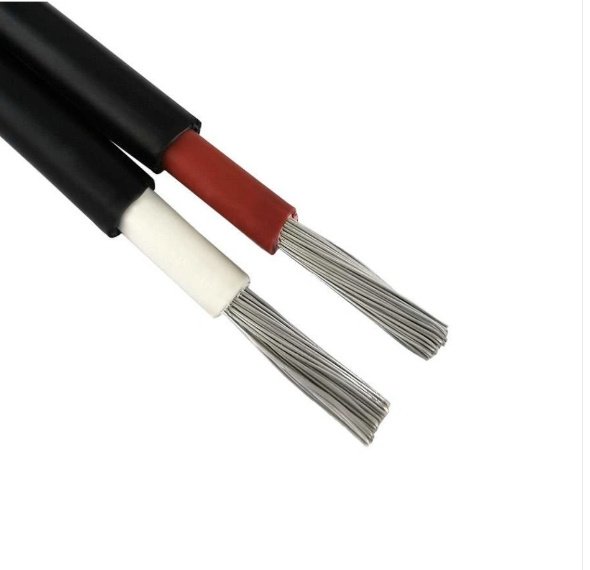
String cables within a PV array — the DC circuits between panels and combiner boxes — are a specific LT application governed by IEC 62930, which defines UV resistance, temperature range, and mechanical requirements that standard LT building wire simply doesn’t meet. Use ordinary cable here and you’ll see insulation cracking within three to five years of UV exposure, depending on climate and cable routing.
From inverter to AC combiner, LT AC cables handle the next step. Then, from the on-site substation transformer to the grid connection point, you’re into HT territory — typically 33 kV XLPE for utility-scale farms, direct buried or in ducts depending on ground conditions and local grid operator requirements.
Standard building wire (e.g., H07V-U) is not suitable for outdoor DC string circuits in solar PV installations.True
IEC 62930 specifies additional requirements for PV cables including enhanced UV resistance, halogen-free sheathing options, and extended temperature range. General-purpose LV wiring standards do not cover these requirements, and using non-compliant cable in string circuits is a common source of premature insulation failure and fire risk in PV plants.
Renewable Energy: Wind Farms
Onshore wind is relatively straightforward. HT 33 kV XLPE cables form the inter-array circuit connecting turbine bases back to the substation, typically direct buried in a trench that follows the access road. Each turbine tower has its own LT cabling for auxiliary power — lighting, control systems, pitch and yaw drives, lift circuits.
Offshore wind adds significant complexity. The inter-array cables are submarine-rated, with water-blocking construction, lead sheath or corrugated aluminium sheath, and armour designed for laying tension and seabed abrasion. These are not catalogue items; they’re project-specific, with lead times that can stretch to 18 months or more for large orders. Getting the cable schedule wrong on an offshore project is an expensive mistake.
Rail and Metro Infrastructure
Traction feeder cables for 25 kV overhead line equipment are among the more demanding HT applications in infrastructure — subject to high fault currents, vibration from adjacent track, and in some tunnel environments, fire performance requirements that add cost and weight to the specification. Single-core XLPE at 33 kV is common for the high-voltage side; at the substation end, termination arrangements in confined switchgear rooms require careful planning.
LT cables in rail environments cover everything from platform lighting and HVAC to signalling, telecommunications, and platform screen door control. These often run in cable trays that pass through areas with significant vibration and temperature swings — a consideration for armour selection and sheath flexibility that sometimes gets overlooked at the design stage.
Commercial Construction and High-Rise Buildings
Most of a high-rise is LT from top to bottom: rising mains in SWA or LSZH, sub-mains to floor distribution boards, final circuits for lighting and power. The decision between SWA and LSZH for rising mains usually comes down to whether the building has a suppression system and how the local authority interprets the fire safety code — that varies more than the standards would suggest.
HT cables appear only when the building is large enough to justify a primary substation on site — a major shopping centre, a university campus, or a large hospital complex where the utility supply comes in at 11 kV or 33 kV. In those cases, the HT feeder cables running from the intake to the on-site transformer are short runs, but they carry the full site load and deserve serious attention to termination quality and fault loop impedance verification.
Frequently Asked Questions About HT and LT Cable
What is the exact voltage boundary between LT and HT cable, and does it vary by country?
Yes, it varies — and the variation causes genuine confusion on cross-border projects. IEC 60038 places the boundary at 1 kV (1,000 V) for low-voltage systems, so strictly speaking anything above 1 kV enters medium- or high-voltage territory under that framework. Indian Standards (IS 1554, IS 7098) use 1.1 kV as the upper limit for LT cable, which is why you’ll see “up to 1.1 kV” on most Indian-manufactured LT cables and datasheets. The term “medium voltage” (MV) covers roughly 1 kV to 36 kV under IEC, which overlaps almost entirely with what the Indian and many Asian markets call HT. In UK practice, 11 kV is the classic HT distribution level. If you’re procuring cable for a project that spans two regulatory environments — a South Asian industrial park with European utility interconnection, for instance — specify the standard explicitly in your purchase order rather than relying on the LT/HT label alone.
Can I use an LT cable on an HT system if I add extra insulation externally?
No. This comes up more often than it should, usually as a stopgap during site shortages. Field-applied tape, heat-shrink, or conduit wrapping cannot replicate what happens inside a factory-extruded XLPE insulation layer: the geometry is controlled to micron-level consistency, the material is homogeneous, and there are no voids or contamination interfaces. The moment you energise even a 3.3 kV system with LT cable, you create the conditions for partial discharge at stress concentrations — particularly at conductor stranding irregularities. Partial discharge is self-reinforcing; it erodes insulation progressively and usually ends in a fault within weeks or months, not years. The screening system in an HT cable also controls the electric field radially; an LT cable has no screen. No amount of external wrapping changes that.
Field-applied external insulation on an LT cable is a safe workaround for temporary HT service.False
External insulation cannot replicate factory-controlled XLPE extrusion geometry or provide the metallic screen required to control radial electric field distribution at HT voltages. Partial discharge will occur at conductor surface irregularities, leading to progressive insulation degradation and eventual cable failure.
Why is XLPE preferred over PVC for HT cables?
Several reasons converge. XLPE has a significantly lower dielectric loss factor (tan δ typically below 0.001 versus 0.05–0.08 for PVC), which matters increasingly as voltage rises — losses are proportional to voltage squared, so at 11 kV or 33 kV the heat generated in PVC insulation becomes a real thermal management problem. XLPE also permits a maximum conductor operating temperature of 90 °C against PVC’s 70 °C, which either increases current-carrying capacity or reduces the conductor cross-section needed for a given load. Long-term, PVC contains plasticisers that migrate over decades, making the material brittle; XLPE doesn’t suffer that degradation mechanism. For any cable intended for 25–40 years of service, the thermal ageing profile of XLPE simply outperforms PVC.
How long does an HT or LT XLPE cable last in service?
The industry design expectation is 30 to 40 years, based on IEC 60216 thermal ageing models. What actually shortens that are: water treeing (moisture ingress at micro-voids in the insulation, particularly in direct-buried runs without adequate water-blocking), repeated overloading above rated temperature, and poor jointing practice. A badly made HT joint — contaminated or insufficiently cleaned cable surface before applying the stress cone — can fail in under five years. Conversely, a well-installed, correctly loaded cable in dry soil has realistically reached 45+ years in utility networks without replacement.
What causes cable failure in HT systems and how is it detected?
Water treeing is the most common slow-failure mechanism in aged XLPE HT cables — moisture diffuses into the insulation over years, forming tree-like conductive paths that eventually bridge to cause a fault. Partial discharge (PD) is both a cause and an early symptom; it can be mapped along an installed cable route using PD detection equipment coupled to the terminations. Thermal overload from sustained overcurrent is the other major cause, usually visible post-fault as carbon tracking along the insulation core. Detection methods in maintenance practice include time-domain reflectometry (TDR) to locate fault position within a metre or two, PD mapping for incipient faults not yet at breakdown, and tan delta (dissipation factor) testing as a condition assessment tool during planned outages. TDR is fast and cheap; tan delta testing requires more preparation but gives you a health index, not just a fault location.
What is the difference between armoured and unarmoured cable, and when is armour required?
Armour — typically steel wire armour (SWA) for three-core cables or steel tape armour for larger single-core runs — provides mechanical protection against crushing, rodent attack, and incidental dig-in damage. It adds weight (roughly 15–30% more for typical SWA LT cable, depending on core size and armour wire gauge) and cost, but for direct-buried installations or runs through areas with vehicle or equipment traffic overhead, it’s not optional. Unarmoured cable belongs in properly installed containment systems: cable trays, conduit, or cable ducts with defined mechanical protection. In practice, a lot of LT cable inside industrial buildings runs unarmoured in tray because the containment is robust; the same route outdoors or below grade almost always needs SWA. HT cables in direct-buried utility distribution are almost universally armoured; the combination of voltage level and burial depth makes mechanical damage consequences too severe to risk otherwise.
How do I request a cable quotation from a manufacturer and what technical data must I provide?
Incomplete RFQs waste time on both sides and frequently result in the wrong cable being priced. At minimum, provide: voltage class (e.g., 0.6/1 kV or 6.35/11 kV, using the U₀/U notation); conductor cross-section in mm² and material (copper or aluminium); number of cores; insulation type (PVC, XLPE); armour type (SWA, STA, unarmoured); outer sheath material and colour if relevant; the applicable standard (IEC 60502-1, IEC 60502-2, BS 6622, IS 7098, or equivalent); installation method (buried, tray, conduit, aerial); required test certificates (routine, type, or third-party witnessed); and quantity with preferred reel lengths. If the project has a specific fire performance requirement — LSZH sheath, for instance — state that separately; it’s a different material family and pricing changes noticeably. Providing the installation method matters because it affects current rating calculations and sometimes armour selection.