
Misrouted control wiring, undersized conductors, or unlabeled bundles don’t just look messy — they cause nuisance trips, ghost faults, and the kind of intermittent gremlins that keep maintenance crews chasing their tails for shifts at a time. A single miswired interlock in a motor control center can halt an entire production line; fixing it under pressure, with the plant manager standing behind you, usually means rework that costs three to five times what proper installation would have taken. Getting control wiring right from the start is not a detail — it’s the difference between a panel that commissioning engineers trust and one that becomes a known problem child for the life of the machine.
Control wiring connects sensors, switches, relays, PLCs, and protective devices so that low-voltage command and feedback signals can flow reliably between them. Its purpose is to carry control logic — start/stop commands, interlocks, status feedback, and fault signals — rather than power loads directly. Conductor cross-sections typically run from 0.5 mm² to 6 mm² depending on signal type and current, and insulation ratings are governed by standards such as IEC 60227 and IEC 60245.
What makes control wiring genuinely interesting — and genuinely dangerous to underestimate — is how invisible it becomes once a panel is closed up. The power conductors are easy to trace and easy to spec. Control wiring is where the logic lives, and logic, when it fails, fails in ways that look like equipment problems, operator errors, or bad sensors before anyone thinks to check the wiring.
Core Functions: Command Transmission, Feedback Loops, and Interlock Circuits
These three roles don’t operate in isolation — they’re constantly interacting inside any running plant, and understanding each one separately is what lets you diagnose faults cleanly rather than chasing ghosts through a rat’s nest of unlabeled conductors.
Command Transmission: Getting the Signal to the Actuator
The simplest picture: a PLC digital output card closes an internal transistor, completes a 24 V DC circuit, and current flows through control wiring to energize a solenoid valve coil. That coil shifts a spool, air moves, a cylinder strokes. The whole event takes milliseconds. The wiring in between is doing real electrical work.
Wire sizing for that circuit is driven by the coil’s inrush current, not its steady-state holding current — and this trips up panel builders more often than it should. A typical 24 V DC solenoid might draw 15–25 mA holding, but the inrush peak can run 5 to 10 times that for the first few milliseconds. In practice, a 0.75 mm² conductor handles most single-solenoid runs without any thermal concern, but if you’re daisy-chaining outputs or running long distances to valve manifolds in a remote cabinet, voltage drop under inrush becomes the real constraint. Run the numbers, don’t just grab whatever spool is closest on the shelf.
Feedback and Status: Closing the Loop
A control system that can only send commands is flying blind. Feedback wiring returns process reality back to the PLC — limit switches confirming cylinder position, pressure switches reporting line conditions, flow switches telling the system whether a pump has actually moved fluid.
These discrete inputs typically arrive as normally open or normally closed dry contacts wired back to the PLC input card over standard control cable. The choice between NO and NC isn’t arbitrary: safety-critical status signals — high-temperature trips, low-level shutdowns — are conventionally wired NC so that a broken wire or open circuit is treated as a fault condition, not a normal “off” state.
Wiring a safety shutdown signal as normally open means a wire break can mask a real fault condition.True
With a normally open wiring convention, an open circuit and a 'safe/normal' state produce identical input card readings, so the control system cannot distinguish between the two. Normally closed wiring inverts this: a wire break drives the input to the de-energized state, which the control system interprets as a fault.
Continuous variable data travels differently. A 4–20 mA analog loop from a pressure transmitter or flow meter requires twisted-pair cable — usually shielded, with the shield grounded at one end only — because the milliamp signal is genuinely vulnerable to induced noise from nearby power cables. In plants where someone has bundled analog pairs alongside 480 V motor leads, the 4–20 mA signal rides a noise floor that makes the reading nearly useless. Segregation isn’t a preference; it’s what makes the measurement accurate.
Interlock Circuits: Hardwired Logic That the Software Cannot Override
Interlocks are where control wiring becomes a direct safety mechanism. A door interlock on a press guard breaks the control circuit to the clutch coil the instant the guard swings open — the machine stops because the circuit is physically interrupted, not because a PLC saw a bit change and executed a rung of logic. A pump permissive interlock holds the starter coil open until a confirmation contact from an upstream valve position switch closes. The pump literally cannot start until the valve is confirmed open.
This distinction matters enormously for functional safety assessments under IEC 62061 and ISO 13849. Software interlocks are faster, easier to modify, and nearly free to implement — which is exactly why they’re insufficient alone for safety-critical functions. A software bug, a corrupted program, or a firmware update can eliminate a software interlock without leaving any visible trace on the machine. Hardwired interlock wiring, physically routed in its own dedicated duct or conduit and separated from standard control circuits, provides a layer of protection that exists independently of the control program.
Signal Segregation Inside the Panel
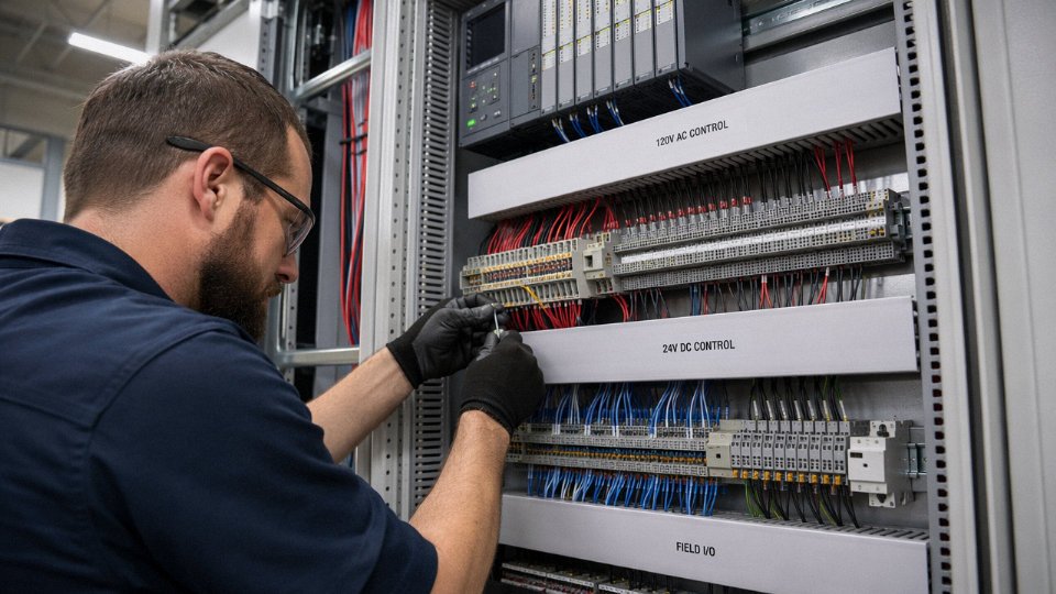
Walk into a well-built control panel and you’ll typically see at least three distinct cable bundles or duct runs: 24 V DC discrete I/O, 120 V AC control circuits (coils, pilot lights, relay outputs), and analog signal wiring. The separation is partly about interference — AC control circuits switching inductive loads generate transients that couple into low-level analog cables if they share a duct — and partly about troubleshooting speed. When a technician needs to trace a fault at 2 a.m., the last thing they need is to unravel mixed-voltage conductors hunting for continuity.
Control wiring can account for 30–50% of total panel assembly labor hours, depending on panel complexity and the degree of prefabrication. Most of that labor is in the routing, bundling, labeling, and termination — not the wire itself. Good signal segregation practice adds a modest amount of early layout time and saves multiples of that downstream in commissioning and maintenance.
How Control Wiring Differs from Power Wiring: Voltage, Current, and Construction
The single most expensive mistake I see on plant floors is someone substituting a power cable for a control cable because “it’s thicker, so it must be better.” It isn’t. These two cable families are engineered around completely different physical constraints, and confusing them causes real problems — signal attenuation, ground loops, failed terminations, and in some cases, insulation breakdown under repeated flexing that a power cable was never designed to survive.
Voltage and Current: Why Thermal Ampacity Barely Matters for Control Wiring
Power cables live in a world of high energy. Distribution feeders in a typical industrial facility run at 400 V to 35 kV, carrying anywhere from tens of amperes on small motor branch circuits to several thousand amperes on main busbars. Conductor sizing for those cables is dominated by thermal ampacity — you’re managing heat generated by I²R losses at meaningful current levels.
Control wiring operates in a fundamentally different regime. Operating voltages typically sit between 24 V DC (PLC I/O, solenoid valve coils) and 690 V AC (some motor contactor auxiliary contacts), and conductor current is almost always below 5 A per circuit, often well below 1 A for digital signals. At those levels, a 1.5 mm² conductor could carry the current without breaking a sweat thermally. What actually determines conductor sizing is voltage drop over run length and mechanical durability at termination points — not heat. A 0.5 mm² conductor is sometimes specified not because it’s thermally marginal but because anything smaller becomes fragile under repeated tightening at screw terminals.
Conductor Count: Running Dozens of Signals in One Sheath
This is where control cable earns its cost. Standard multi-core configurations — 4, 7, 12, 19, 27, 37 cores — let you bundle dozens of discrete signals into a single cable run from the panel to a field device cluster. That matters enormously for conduit fill calculations and, perhaps more importantly, for termination labor. In a medium-sized automation panel, control wiring can account for 30–50% of total assembly labor hours; every reduction in cable runs compounds across the whole project schedule.
Control cables commonly come in multi-core configurations up to 37 cores in a single sheath under IEC standards.True
Standard IEC and European cable catalogs list control cables in core counts of 4, 7, 12, 19, 27, and 37, all under a unified outer sheath, primarily per IEC 60227 and manufacturer standards aligned with VDE 0815.
Insulation and Sheath: PVC, XLPE, and Why LSZH Is Non-Negotiable in Some Facilities
PVC insulation, rated per IEC 60227 at 300/300 V up to 450/750 V depending on construction, covers the majority of general industrial control wiring. It’s cheap, flexible enough for fixed installation, and well understood. XLPE steps in when you need better chemical resistance or elevated temperature ratings — a food processing environment with frequent wash-down, for instance, or wiring routed near heat sources. LSZH (low-smoke, zero-halogen) sheathing isn’t optional in tunnels, offshore platforms, rail rolling stock, or any enclosed public space; IEC 60332 flame propagation requirements often dictate it, and local fire codes in many jurisdictions make it mandatory regardless of what a specifier might prefer.
Shielding: Foil, Braid, and the Ground-Loop Trap
Analog signal cables — 4–20 mA loops, thermocouple extensions, RTD wiring — require shielding that digital control cables often don’t. Foil shields offer nearly 100% coverage and are standard on instrumentation pairs; braided shields add mechanical robustness and are common on cables that see movement. The operating rule: ground the shield at one end only, typically the panel end. Ground both ends and you create a ground loop that injects noise directly into the signal path. Individual pair shielding is specified when multiple analog signals share one cable and crosstalk between pairs is a concern — a thermocouple and a 4–20 mA loop running together being a classic case.
Flexibility Ratings: Fixed Installation vs. Drag Chain vs. Robotic Arm
A cable routed inside a control panel and never touched again has completely different mechanical requirements from one running through a drag chain on a CNC machine that cycles 10 million times over its service life. Fixed-installation control cables use standard stranded conductors. Drag-chain and continuous-flex applications demand fine-stranded conductors wound in specific lay configurations, oil-resistant outer sheaths, and tested flex-cycle life — often specified per VDE 0282 Part 10 or equivalent, with ratings ranging from roughly 5 million to over 10 million flex cycles depending on bend radius and speed. Robotic arm cables are more demanding still, requiring torsional flex resistance on top of lateral bending.
Using a standard fixed-installation cable in a drag chain is a maintenance time bomb. Conductors work-harden and fracture, typically at termination points first, producing intermittent faults that are genuinely difficult to diagnose under production conditions.
Comparison: Power, Control, and Instrumentation Cable at a Glance
| Parameter | Power Cable | Control Cable | Instrumentation Cable |
|---|---|---|---|
| Voltage rating | 600 V to 35 kV typical | 300/300 V to 450/750 V (IEC 60227) | 300/500 V typical |
| Current capacity | Tens to thousands of A | Usually below 5 A per conductor | Below 1 A (signal level) |
| Conductor count | 1–5 cores typical | 4 to 37 cores common | 1 to 12 pairs common |
| Shielding | Rarely required | Sometimes (depends on signal type) | Almost always (foil and/or braid) |
| Insulation type | XLPE, EPR, PVC | PVC, LSZH, XLPE | PVC, LSZH, PTFE (high temp) |
| Typical application | Motor feeders, distribution | PLC I/O, solenoid control, interlocks | 4–20 mA loops, thermocouples, RTDs |
The instrumentation column deserves attention because procurement teams frequently conflate it with control cable. They’re close relatives but not interchangeable — the shielding architecture alone is different enough to cause signal integrity problems if you substitute one for the other on a sensitive analog loop.
Control Wiring in Motor Control Centers, PLCs, and SCADA Panels
MCC Bucket Architecture — Where Control Wiring Actually Lives
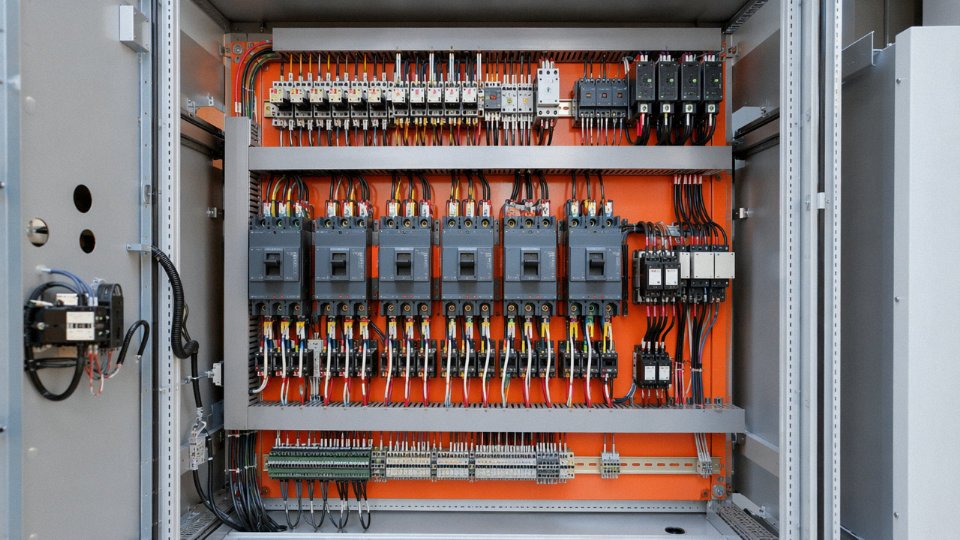
A motor control center is, in practical terms, a steel cabinet full of compartmentalized “buckets,” each containing a starter, breaker, and the control wiring that makes the whole assembly behave like something other than a manual switch. Inside each bucket, a control power transformer — typically stepping 480 V or 600 V line voltage down to 120 V AC, or fed from a separate 24 V DC rail — supplies power to the contactor coil circuit. That coil circuit is wired through a chain of normally-open and normally-closed contacts: the overload relay auxiliary contact, a local/remote selector switch, possibly an E-stop mushroom head, and the pilot device or PLC output that actually initiates the start command.
Getting that wiring sequence wrong — say, placing the overload auxiliary contact downstream of the contactor instead of upstream — means the overload trips but the control circuit sees nothing. The contactor de-energizes correctly but no fault signal reaches the PLC. Operators assume the motor ran to completion. It didn’t.
Control wiring leaves the MCC bucket via multi-pair cables routed through cable tray or conduit to field junction boxes. Wire sizes in this section typically fall in the 1.0–2.5 mm² range, depending on the length of the run and whether it carries a coil circuit or a pilot lamp load. Runs exceeding roughly 150–200 meters with small AC coil loads can see enough voltage drop to cause erratic contactor chatter — a frustrating fault that looks mechanical until someone actually measures the coil terminal voltage under load.
PLC I/O Wiring — Terminal Blocks, Commons, and the Discipline of Labeling
PLC digital I/O wiring is where panel builders either establish a maintainable system or create a troubleshooting nightmare that haunts the plant for years.
Field devices — limit switches, proximity sensors, push buttons — land on terminal blocks inside the panel. Those terminal blocks then connect via short jumpered wires to the PLC’s input card terminals. The logic here is deliberate: a field cable can be disconnected and megged, or swapped during commissioning, without disturbing the internal panel wiring. Direct termination of field cables to PLC cards skips that buffer and is, in practice, a shortcut that costs more time than it saves.
Keeping input card commons and output card commons strictly separate is non-negotiable on any installation where you’re mixing sourcing and sinking devices, or where input circuits could be influenced by output switching transients. It also matters for fault isolation — a shorted field output should blow a fuse or trip a card, not drag down the entire input common and blind the PLC to half its field signals.
Every conductor gets a wire number that matches the drawing. Every conductor gets a ferrule, crimped with the right tool — not pliers, not a generic crimp tool that leaves the ferrule half-formed and prone to pull-out. Wire markers at both ends. This is non-negotiable in any CE-marked or UL-listed panel, and it’s genuinely the difference between a two-hour fault-find and an eight-hour one.
NFPA 79 and IEC 60204-1 both specify wire duct fill limits in the range of 40–60% of usable duct cross-section for control wiring runs inside machinery panels.True
Both standards address wire duct fill to ensure heat dissipation, maintainability, and the ability to add or remove conductors without damaging insulation on adjacent cables. The 40–60% range is widely cited in panel-building practice and reflects the language in IEC 60204-1 clause 13.5 and NFPA 79 guidance on wireway fill.
Color coding follows IEC 60446 in most international projects: blue for neutral, green/yellow stripe strictly for protective earth, and other colors — black, red, grey, white, depending on the panel builder’s convention — for line and control conductors. Mixing these up is not a minor documentation error. An electrician performing live work on a panel where someone used green wire for a 120 V AC control circuit is in a genuinely dangerous situation.
SCADA and DCS Marshaling — How Signals Travel from Field to Control Room
In a SCADA or DCS installation, the signal path is longer and the wiring discipline matters differently. A 4–20 mA signal from a pressure transmitter, or a discrete output to a control valve solenoid, originates in the field and travels — sometimes hundreds of meters — to a local junction box. Multiple signals are bundled from that junction box via a multi-pair home-run cable back to a marshaling panel, usually located near the control room or in the MCC room.
At the marshaling panel, each signal lands on a terminal block row. Cross-wiring then connects those terminals to the DCS I/O cabinet, which allows the system integrator to modify I/O assignments without re-pulling field cables. This layer of cross-wiring adds labor, but on a project with 500+ I/O points and a control philosophy that changes three times during commissioning, it earns back its cost easily.
Individually shielded pairs are essential in these multi-pair instrumentation cables — not an upgrade, not optional. An unshielded pair carrying a milliamp-level analog signal routed in the same bundle as switched DC output wiring will pick up enough noise to make the signal meaningless. The shield must be grounded at one end only, typically at the marshaling panel end, to avoid creating a ground loop.
Shandong Jinda’s multi-core and shielded control cable range — conductors from 0.5 mm² up to 6 mm², available with PVC, XLPE, or LSZH insulation jackets — addresses exactly this spectrum of applications. LSZH constructions are increasingly specified for MCC rooms and control rooms where smoke toxicity during a cable fire matters, and the 0.5 mm² pairs suit analog instrument loops while the larger cross-sections handle contactor coil runs and solenoid circuits without derating concerns. For panel builders working at volume, consistent dimensional tolerances on the cable mean terminal block selections and wire duct fill calculations hold across an entire project, which is a more practical benefit than it sounds.
Signal Integrity, Shielding, and Noise Rejection in Control Wiring Runs
A control cable can be perfectly sized, correctly terminated, and still fail to deliver reliable signals if the electrical environment around it is hostile. In heavy industrial plants, that environment almost always is.
Sources of Noise That Actually Cause Problems
Variable frequency drives are the biggest offender in most modern facilities. Their IGBT switching stages operate at carrier frequencies typically between 2 kHz and 16 kHz, generating high-frequency transients that radiate aggressively from both the drive output cables and the motor itself. Run a 0–10 V analog speed reference cable in the same tray as a VFD output lead for any meaningful distance and you will see it — erratic speed hunting, PLC analog inputs reading phantom values, occasionally a drive fault that nobody can reproduce on demand.
Large motors create a different problem: inductive kickback at start and stop, plus continuous magnetic field radiation proportional to current. Welding equipment is worse in a different way — it radiates broadband EMI across a wide frequency range, and the arc-strike transients can couple into anything nearby, including shielded cables that are improperly grounded.
The practical consequences are false triggering on digital inputs, corrupted 4–20 mA readings, and — less obviously but expensively — intermittent PLC faults that maintenance teams spend days chasing without finding a hardware defect.
How Noise Couples Into Control Wiring
Two mechanisms dominate. Capacitive coupling occurs when two conductors run in close proximity with a voltage difference between them; the parasitic capacitance formed between them passes high-frequency noise onto the control wire. Inductive coupling happens when a changing magnetic field from a power conductor induces a voltage in a nearby loop formed by the control circuit.
Both mechanisms are highly distance-sensitive. Doubling the separation between a power cable and a control cable reduces capacitive and inductive coupling substantially — which is why the widely used rule of thumb is to maintain at least 200–300 mm of physical separation when control cables run parallel to power cables carrying more than roughly 100 A. Routing control cables orthogonally (crossing at 90°) rather than parallel is even more effective where tray layout allows it. Steel conduit around control cables, or a steel divider plate in a shared cable tray, adds a useful degree of magnetic shielding on top of the separation.
Shielded Cable: Foil, Braid, and the Grounding Rule That People Keep Getting Wrong
For analog signal pairs — 4–20 mA loops, thermocouple extension leads, RTD circuits — an aluminized polyester foil shield with a drain wire is usually sufficient and cost-effective. Foil gives 100% coverage, which matters for continuous low-frequency noise rejection. Tinned copper braid shields run 85–95% optical coverage but handle mechanical flexing better and provide lower shield resistance at higher frequencies, making them the better choice where cables move (robot arms, drag chains) or where high-frequency transients from VFDs are the primary threat.
The grounding rule is simple and frequently violated: ground the shield at one end only — the control panel end. Leave the field end floating. Grounding both ends creates a loop antenna that actively picks up magnetically induced currents and routes them through the very conductors you were trying to protect. In practice, a small capacitor (typically 10–100 nF) at the field end is sometimes used to provide high-frequency grounding without creating a DC loop, but verify this against your system’s EMC requirements before specifying it.
Grounding a cable shield at both ends always improves noise rejectionFalse
Grounding at both ends creates a ground loop. Circulating currents induced in the loop by magnetic fields are injected directly into the signal circuit. Single-point grounding at the panel end is the standard practice for instrumentation and control cables.
Twisted Pairs and Why Twist Rate Matters
Twisting a signal pair works because each half-twist exposes the two conductors to equal and opposite induced voltages, which cancel at the receiver — a differential input rejects what is called common-mode noise. The effectiveness depends partly on twist rate: tighter twists (toward 20 twists per meter) cancel higher-frequency interference more effectively. For RTD and thermocouple circuits, typical twist rates of 6–12 twists per meter are usually adequate. For faster differential signals or environments with aggressive VFD noise, 15–20 twists per meter is worth specifying.
Voltage Drop on 24 V DC Control Circuits
This gets underestimated. The formula is straightforward:
V_drop = 2 × L × I × R_per_meter
The factor of 2 accounts for both the outgoing and return conductors. For 1.5 mm² copper conductor, resistance is roughly 12.1 mΩ/m at 20 °C. A 100 m run carrying 0.5 A produces:
V_drop = 2 × 100 × 0.5 × 0.0121 ≈ 1.21 V
On a 24 V DC coil, that is usually fine — most contactors operate reliably down to 85% of rated voltage. But consider a 24 V sensor with a 21.6 V minimum supply threshold: that same run may cause intermittent sensor dropout, especially if the supply rail sags slightly under load. The fix is to upsize the conductor (moving to 2.5 mm² drops the loss to roughly 0.73 V) or to use a local 24 V supply closer to the field device. Neither option is expensive. Troubleshooting a voltage-starved sensor after installation always is.
EMC Standards as a Procurement Tool
IEC 61000-4 series tests — covering conducted immunity, radiated immunity, EFT/burst, and surge — give procurement teams a documented basis for specifying cables and installed systems. When a cable is supplied with test data demonstrating compliance to IEC 61000-4-4 (electrical fast transient) or IEC 61000-4-6 (conducted RF immunity), that shifts some liability for EMC performance to the supplier and gives the end user something to reference in commissioning sign-off.
In practice, specifying “IEC 61000-4 compliant” without stating the specific test level means little. Ask for the test level — Level 3 or Level 4 for heavy industrial environments — and get the test report, not just a declaration.
Installation Standards, Color Coding, and Labeling Requirements for Control Wiring
Every wiring error caught during installation costs a fraction of what it costs during commissioning — and a tiny fraction of what it costs after a machine goes into service. Standards exist precisely because human memory is unreliable under production pressure, and because the electrician who installed a panel is rarely the technician who troubleshoots it three years later.
Key Standards That Govern the Work
IEC 60204-1 (Safety of Machinery — Electrical Equipment of Machines) is the primary international reference for control panel wiring. It specifies conductor sizing, color conventions, terminal marking schemes, and physical segregation — essentially a complete rulebook for everything from the incoming isolator down to the last PLC input terminal. NFPA 79 covers the same ground for North American industrial machinery and tracks IEC 60204-1 closely in many areas, though there are real differences in permitted wire colors and some grounding practices that will catch an engineer off guard if they assume the two are interchangeable.
Both standards share one non-negotiable requirement: every conductor must be identifiable at each end. Not just traceable with a meter — identifiable by inspection. That distinction matters enormously when a maintenance technician is working live on a partially energized panel at 2 a.m.
Color Coding — Less Flexibility Than Most People Assume
IEC 60446 and IEC 60204-1 together define a color scheme that is not a suggestion. Green/yellow bicolor is reserved exclusively for protective earth conductors. Using it for anything else — even temporarily, even in a pinch — is a serious violation that creates a genuine electrocution hazard, and I’ve seen it done with spare wire on deadline-driven projects. Blue identifies the neutral conductor. Red or black designates AC line conductors depending on the regional convention; in DC circuits, dark blue or black marks the positive conductor and white or gray marks negative.
The green/yellow bicolor wire color is reserved exclusively for protective earth conductors under IEC 60446 and may not be used for any other circuit purpose.True
IEC 60446:2007 and IEC 60204-1:2016 both explicitly prohibit the use of green/yellow bicolor for any conductor other than a protective earth conductor. This is a mandatory requirement, not a recommendation.
In practice, specifying wire colors at the Bill of Materials stage — rather than leaving it to the panel shop — prevents substitution problems when specific colors are back-ordered.
Wire Marking and Why It Pays Off Fast
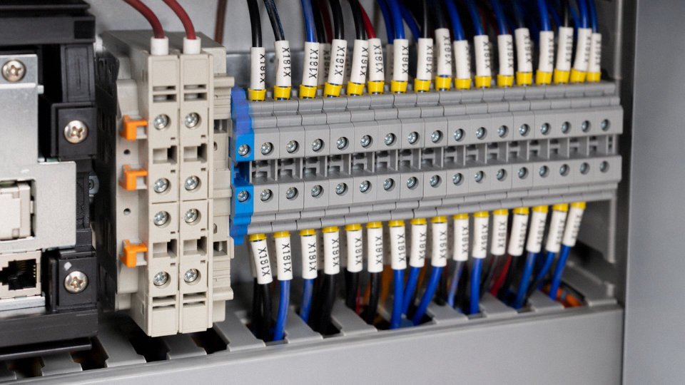
The professional standard is alphanumeric wire numbering derived directly from the schematic: typically formatted as source terminal to destination terminal, so a wire connecting terminal X3:7 on a relay to terminal A1:4 on a contactor carries a label that reflects exactly that path. Heat-shrink sleeve markers or clip-on ferrule markers applied at each wire end are both acceptable; heat-shrink holds up better in environments with oil mist or vibration.
The payoff is concrete. A well-labeled panel with a clean wiring schedule cuts fault-finding time from several hours to under 30 minutes in most cases — the range depends heavily on panel complexity and how legible the original schematic is. Unlabeled or inconsistently labeled panels, on the other hand, often require a technician to re-trace every wire before they can even begin diagnosing a fault.
Segregation, Routing, and Bend Radii
Control cables must be physically separated from power cables — not just in separate ducts within the same tray, but ideally in separate trunking or cable trays entirely. The coupling between a 400 V motor feeder and a 24 V DC PLC input line can be enough to cause spurious signals, particularly in long runs or where cables run parallel for more than a few meters. Safety-critical control circuits — emergency stop loops, safety relay wiring — typically require fire-rated conduit as well.
Bend radii are often ignored until a cable fails early. For fixed installations, the minimum is generally 6–8 times the cable’s outer diameter; flexible applications push that to 10–15 times. Going tighter than these limits stresses the insulation at the bend and, in multicore cables, can cause differential conductor lengths that create intermittent continuity issues — the worst kind to diagnose.
Documentation, CE Marking, and Handover Packages
Most serious industrial clients require a complete documentation package as a condition of acceptance: as-built wiring diagrams reflecting what was actually built (not just what was designed), terminal block schedules, and a cable schedule listing each cable’s identifier, route, core count, cross-section, and connected equipment at both ends. Under the EU Machinery Directive, this documentation supports CE marking and is part of the Technical File the manufacturer must maintain.
Skipping or abbreviating this package saves a few hours at handover and creates serious problems every subsequent time the machine needs modification or repair. Plants that maintain clean documentation typically show measurably lower maintenance labor costs over a 10-year horizon — the exact difference depends on machine complexity and maintenance frequency, but the direction is consistent.
Pre-Energization Testing
Before any control circuit goes live, IEC 60204-1 requires insulation resistance testing at a minimum of 1 MΩ measured at 500 V DC. Continuity checks verify that every conductor is actually connected where the schematic says it is — not just that it’s plugged in at both ends, but that it’s the right conductor. Polarity checks on DC circuits prevent damage to PLCs and sensors that have no reverse-polarity protection. Shield continuity and single-point grounding verification rounds out the pre-commissioning checklist for screened cables.
Rushing this sequence to meet a startup deadline is a predictable source of damaged PLC input cards and unexplained sensor behavior during early production runs. The testing itself, done properly, takes a few hours on a typical machine panel. The repairs it prevents can take days.
Selecting the Right Control Cable: Conductor Size, Core Count, and Insulation Grade
Getting this decision wrong costs more than the cable. A misspecified control cable might work fine for six months, then fail during a summer heat wave, or pick up enough noise to cause spurious PLC faults that take a maintenance team days to trace. The selection process isn’t complicated, but it does need to be systematic.
Step 1 — Define the Signal Type First
Everything else follows from this. A 24 V DC discrete input to a proximity sensor has almost nothing in common electrically with a 4–20 mA loop from a pressure transmitter 200 m away, or a thermocouple extension pair running near a 400 V drive cabinet.
Thermocouple extension cables must use conductors made from the same alloy pair as the thermocouple itself — copper won’t do, regardless of what’s in the cable store. RTD cables need low, matched conductor resistance across all three or four wires; cross-section matters for balance, not just current capacity. High-speed digital signals — encoder quadrature, for instance, running at 100 kHz or above — demand controlled impedance and tight twist pitch; standard multi-core control cable simply isn’t designed for that. Sorting signal type before anything else prevents expensive re-pulls.
Step 2 — Conductor Cross-Section: Resistance Tables, Not Guesswork
For discrete control signals below roughly 2 A, 0.5–1.5 mm² stranded copper (Class 5 per IEC 60228) covers most situations. Pilot lights, selector switches, pushbuttons drawing up to 5 A sit comfortably on 1.5–2.5 mm². But cross-section isn’t just about current capacity — on runs exceeding 100 m, voltage drop can become the binding constraint, particularly for 24 V DC circuits where a 2–3 V drop can push a PLC input below its guaranteed threshold voltage. Calculate using the resistance values from IEC 60228 Class 5 tables, not a back-of-envelope approximation. Upsizing from 0.75 mm² to 1.5 mm² on a 150 m analog loop costs very little in cable but eliminates a fault mode that will be nearly impossible to diagnose from the control room.
Step 3 — Core Count and the 20% Spare Rule
Home-run field cables — the ones running from a junction box or marshalling panel out to field instruments or actuators — should include a spare core allocation of around 20%. In practice that means: if your loop schedule calls for 10 cores, specify a 12-core cable. Common manufactured core counts are 4, 7, 12, 19, and 27; matching your count to one of these avoids special-order lead times and excess cost. Spares aren’t waste. They’re insurance against design changes during commissioning, and they save the cost of pulling a second cable when the inevitable instrument is added eighteen months after handover.
Step 4 — Insulation and Jacket Material
PVC is the default for good reason: it’s cost-effective, widely available, and entirely adequate for dry indoor installations at temperatures up to 70°C. Step outside those conditions and the calculus changes fast.
XLPE handles continuous temperatures to around 90°C and resists a broader range of chemicals — useful near process equipment. LSZH (low smoke, zero halogen) is non-negotiable in tunnels, offshore platforms, public transport infrastructure, and increasingly in any facility where occupants can’t evacuate quickly; building codes in many countries now mandate it regardless of what the electrical contractor prefers. Machine tool applications with exposure to cutting fluids, hydraulic oil, or drag-chain flex cycles need PUR or TPE jackets — standard PVC cracks or swells under those conditions, sometimes within months.
LSZH cable is required by IEC 60332 and related standards in confined or public spaces due to its reduced toxic smoke emission during fire events.True
IEC 60332 series covers flame propagation and smoke emission testing for cables. LSZH materials are specified precisely because halogen-based combustion gases (HCl from PVC, for example) are corrosive and toxic in enclosed environments, and regulatory requirements in offshore, tunnel, and public building applications reflect this.
Step 5 — Shielding Configuration
Simple 24 V DC discrete wiring in a dedicated cable tray, well-separated from power cables, usually needs no shielding. Once you move to analog — a 4–20 mA loop, a resistance temperature measurement, anything where a few millivolts of induced noise matters — shielding becomes essential. A single analog loop is typically served by an overall foil shield with drain wire, grounded at one end only to avoid ground loops. Multi-pair instrumentation cables carrying several analog signals should have individual pair shields plus an overall shield; without individual pair shielding, crosstalk between pairs running in parallel can corrupt readings even when the cable itself is well-shielded from external sources. Braid shields add mechanical durability and perform better against broadband high-frequency noise — relevant near VFD output cables or high-current bus systems.
Step 6 — Environmental Rating Verification
This is where specifications get missed, especially on projects where the electrical engineer is working from a general arrangement drawing rather than walking the actual route. Temperature range, UV exposure on outdoor cable bridges, chemical splash in washdown areas, burial depth for direct-buried runs, and flex life for trailing cables on moving machinery — each maps to specific IEC or VDE ratings that the cable manufacturer’s datasheet should explicitly confirm, not imply.
Jinda’s engineering support team works directly with international buyers to run through this selection process application by application. With certified test data available for IEC 60227 and IEC 60245 rated products across the full insulation range from 300/300 V through 450/750 V, the process of matching a cable specification to a real installation condition is faster and more defensible than working through generic catalog tables alone.
Control Wiring in Hazardous Areas, Offshore, and High-Temperature Environments
Standard industrial control wiring practice gets you a long way — but step into a petrochemical plant, an offshore platform, a smelter, or an underground mine and the rules change fast. In these environments, a wiring failure isn’t a production inconvenience; it’s a potential fatality or a regulatory shutdown. The cable specification work that happens at the desk has real safety consequences on the plant floor.
Hazardous Area Classification and Protection Concepts
The IEC 60079 series divides explosive atmospheres into zones based on how frequently a flammable atmosphere is present. Zone 0 means it’s there continuously; Zone 1, periodically during normal operation; Zone 2, only under abnormal conditions. For combustible dust, the equivalent zones are 20, 21, and 22. Every piece of control wiring that enters these zones must belong to an approved protection concept — this isn’t a suggestion, it’s the basis of your installation’s Ex certification.
Three concepts come up most in control wiring: intrinsic safety (Ex i), increased safety (Ex e), and flameproof enclosures (Ex d). Ex i is the one that directly governs the cable parameters. The idea is that the circuit is limited in stored energy — through certified Zener barriers or galvanic isolators — so that even a fault or a spark cannot ignite the surrounding atmosphere. What engineers sometimes underestimate is that the cable itself carries entity parameters: defined maximum capacitance (C_cable) and inductance (L_cable) per unit length. These must be added to the connected field device’s internal values, and the total must stay within the certified entity parameters of the barrier. Cable length limits fall directly out of this calculation. A 1.5 mm² twisted pair with typical capacitance around 100–200 pF/m can support runs of several hundred meters in many installations, but in a Zone 0 application with tight barrier limits, you might be restricted to 80–100 m. Always check the barrier certificate, not just the cable datasheet.
Cable Glands and Sealing — Where Procurement Gets It Wrong
Certified Ex cable glands are not interchangeable with standard industrial glands. A proper Ex gland must grip both the inner and outer sheaths, terminate armor correctly, and maintain the IP66 or IP68 rating of the enclosure it’s entering. Using a standard nickel-plated brass gland in a Zone 1 installation — even briefly, during commissioning — can void the enclosure’s Ex certification. This is a real procurement trap when a project is sourcing accessories from multiple suppliers. Specify glands and cables together, from suppliers who can provide the matched documentation.
Offshore and Marine Environments
Class society rules — DNV, Lloyd’s, ABS — and IMO SOLAS regulations require control cables on vessels and offshore installations to pass IEC 60332-3 (bundle flame propagation) and IEC 60331 (circuit integrity under fire). Halogen-free, mud-resistant, seawater-resistant jacket compounds are effectively standard now on most offshore projects. The logic is straightforward: a burning cable that produces dense, toxic smoke in a confined platform corridor kills people before the fire does.
Control cables used offshore must pass IEC 60332-3 bundle fire propagation testing to comply with class society rules.True
DNV, Lloyd's Register, and ABS all reference IEC 60332-3 in their cable approval requirements for offshore and marine applications, consistent with IMO SOLAS fire safety objectives.
High-Temperature Applications and Thermocouple Wiring
Control wiring near kilns, reheat furnaces, or steam headers needs to be specified for the actual ambient temperature, not the rated panel temperature. Silicone-insulated cables handle roughly 180°C continuous; glass-fiber-braided constructions can reach 300°C or beyond, depending on the binder and jacket. Running a standard PVC-insulated control cable through a cable tray that passes 1.2 meters from a 900°C kiln shell is a slow failure — insulation softens, shorts develop intermittently, and the fault is maddening to trace.
Thermocouple extension cables are a specific case that deserves separate attention. A Type K thermocouple uses Chromel-Alumel alloys; its extension cable must use the same alloy pair, not copper. If copper conductors are substituted — even for a short run back to a junction box — you introduce an uncompensated reference junction error that can throw temperature readings off by 10–30°C or more, depending on the ambient temperature at that junction. Type J, Type T, and other thermocouple types each have their own matched alloy codes. The cable jacket color coding follows IEC 60584-3 (green for Type K in IEC convention, yellow in ANSI/ASTM) — and getting the convention wrong between a European instrument and an American DCS is, in practice, a very easy mistake to make on multinational projects.
Mining Applications
Mobile mining equipment — shuttle cars, continuous miners, longwall shearers — puts a completely different set of demands on trailing cables. The cable flexes thousands of times over its service life, drags across abrasive surfaces, and operates in atmospheres that may contain methane or coal dust. Steel wire braid or armor provides mechanical protection; the outer sheath needs to be both flame-retardant and antistatic, since static charge buildup on a cable sheath is an ignition risk in gassy mines. IEC 62931 covers trailing cable performance requirements, and most national mining safety agencies layer additional requirements on top — in practice, you need to know which national regime applies before finalizing the specification.
The throughline across all these environments is the same: the cable is part of the safety system, not just a signal carrier. Specifying it correctly from the start is substantially cheaper than a field retrofit after a regulatory audit.
Maintenance, Fault Diagnosis, and Service Life of Control Wiring Systems
Control wiring tends to get ignored until something stops working. Power cables get attention because failures are dramatic — a tripped breaker, a blown fuse, something obviously wrong. Control wiring fails quietly: an intermittent fault on a stop circuit, a PLC input that reads unreliably, a motor that won’t start on the first press but will on the third. By the time the fault is obvious, you’ve already lost production time and your maintenance crew has spent hours chasing ghosts.
How Control Wiring Actually Fails
Thermal cycling is the slow killer. In panels where ambient temperature swings significantly between shifts — near furnaces, on outdoor switchgear in northern climates — PVC insulation expands and contracts repeatedly at terminal entry points. Over years, this work-hardens the insulation, eventually producing fine cracks. You won’t see them until you flex the cable. Chemical attack follows a similar slow trajectory: hydraulic fluid mist, cutting oil vapor, and cleaning solvents all degrade PVC at different rates depending on concentration and temperature, and the damage is usually invisible until the insulation is brittle enough to crumble under a screwdriver.
Conductor fatigue fractures deserve more attention than they typically get, especially in flexing applications — pendant controls, robot dress packs, cable carriers on linear axes. A stranded conductor rated for static installation can fracture after relatively few flex cycles if the bend radius is too tight or if the cable is twisted rather than bent in a single plane. The resistance reading stays normal until the last few strands break, then you get an intermittent open that defies diagnosis with a basic multimeter.
Loose terminations cause more unplanned downtime than most engineers realize. A screw-clamp terminal that wasn’t torqued to spec — or that was torqued correctly but vibrated loose over a few years — creates a high-resistance joint. At control current levels, this may not trip anything. It just introduces enough resistance to pull a 24 V DC signal down far enough that a PLC input reads erratically. Corrosion at the conductor-terminal interface compounds this, particularly with stranded copper in humid environments where the individual strands oxidize faster than solid conductors.
Chafe damage is mostly a wiring installation problem that becomes a maintenance problem later. Cables routed against cabinet knockouts, through metal gland plates without adequate bushings, or touching moving parts wear through their insulation on a timescale of months to a few years depending on frequency of movement and edge sharpness.
Preventive Maintenance That Actually Catches Problems Early
Annual insulation resistance testing with a 500 V DC megohmmeter on all critical control circuits is the single most cost-effective task in a control wiring PM program. Healthy PVC-insulated control cable in moderate service typically reads well above 100 MΩ; anything below 10 MΩ warrants investigation, and readings below 1 MΩ should trigger replacement before the next scheduled outage rather than after an unplanned one.
Annual insulation resistance testing at 500 V DC with a target above 10 MΩ is an established industry practice for assessing control cable health before failure occurs.True
This threshold and test voltage align with IEC 60364-6 commissioning and periodic verification guidance and are widely referenced in industrial maintenance standards for low-voltage control systems.
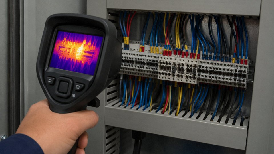
Thermal imaging of terminal blocks during live operation catches loose connections that a torque wrench missed. A single loose 24 V control terminal rarely shows up on a thermal image by itself — you’re looking for temperature differentials across adjacent terminals in the same circuit, not absolute hot spots. Do this scan annually at minimum, more often in high-vibration environments.
Torque verification on screw-clamp terminals matters more than most maintenance programs acknowledge. Terminal manufacturers publish torque values — typically in the range of 0.5 to 1.5 N·m for the wire sizes common in control panels, though this varies by terminal series — and those values should be in your PM checklist, not left to technician feel.
Visual inspection of cable entry points and gland seals sounds trivial but catches chafe damage and seal deterioration before moisture ingress degrades insulation.
Diagnosing Faults Systematically
The temptation when a control circuit fails is to start pulling wires. Resist it. Start by confirming control power voltage at the supply fuse or circuit breaker — a surprising number of “wiring faults” are actually blown control fuses or a tripped GFCI. Then work from the output device backward to the source using a multimeter, checking voltage presence and continuity at each terminal in sequence using the documented wire schedule. Without that schedule, you’re guessing.
Lock out and tag out before opening any junction boxes or splice points. This is obvious, but intermittent-fault diagnosis creates pressure to work live. Don’t.
Intermittent faults are the genuinely difficult ones. A fault that disappears when you open the panel door has usually disappeared because thermal expansion caused a marginal connection to reseat, or because the vibration that was inducing contact bounce stopped when the machine paused. Useful techniques: install a data logger on the relevant PLC I/O channel and let it run through a full production cycle; use a clamp meter logging current on the control circuit continuously; carefully flex suspected cable sections — particularly near tight bends and at terminal entries — while monitoring continuity on a meter. That last technique finds conductor fatigue fractures and marginal insulation chafes that nothing else will.
Service Life and Knowing When to Replace
Well-installed PVC control cable in a clean environment at moderate temperature — say, a climate-controlled assembly plant — can realistically achieve 20 to 30 years of service life. XLPE-insulated cable pushes that to 30 to 40 years, give or take, depending on operating temperature and UV exposure. These are ranges, not guarantees; a cable in a steel mill or chemical plant may need replacement in 10 to 15 years.
Replacement triggers: insulation resistance below 1 MΩ under test, visible cracking or discoloration of insulation, repeated intermittent faults on the same run despite terminal maintenance, and any major control system upgrade that requires reconfiguring circuits. Don’t try to repurpose old wiring for a new PLC architecture — the labor cost of future troubleshooting will exceed the cost of new cable.
Splicing and Repair
Replace control cable full-length whenever the project allows it. A mid-run splice is a future fault point and a documentation burden. When a full replacement genuinely isn’t feasible — a cable buried in conduit that’s impossible to re-pull without a major shutdown — use an IP-rated junction box with proper terminal blocks, not tape-wrapped butt splices. Document the splice location on as-built drawings immediately, not later. In practice, “later” means the next maintenance engineer who opens that panel three years from now has no idea the splice exists.
Frequently Asked Questions About Control Wiring
Can I use power cable instead of control cable for a control circuit?
Technically, for a simple single-phase control loop running at mains voltage, a two-core power cable won’t immediately fail. But “won’t immediately fail” is a low bar. Power cable is built for different priorities — high current capacity, robust earth conductors, phase identification — not for the multi-core configurations, shielding options, and conductor flexibility that control circuits actually demand. You’ll also run into IEC 60204-1 color-coding requirements almost immediately, since power cables don’t come in the orange, grey, or light blue conductors that control wiring standards specify. Bulk increases too, sometimes substantially, which matters when you’re routing twenty circuits through the same cable tray. Use dedicated control cable. It costs less per circuit over the length of the job, not more.
What voltage rating do I need for 24 V DC control wiring?
This confuses a lot of people, including some experienced panel builders. Most 24 V DC control circuits use 300/300 V or 300/500 V rated cable — cable rated at many times the actual operating voltage. The rating isn’t telling you the maximum you’ll ever apply; it defines insulation quality. Higher-rated insulation handles transients better, ages more slowly under thermal cycling, and resists mechanical nicks without immediately compromising the circuit. A 24 V DC solenoid valve circuit that sees an inductive kick when the coil de-energizes can generate voltage spikes well above the nominal supply. Thin insulation on underrated cable degrades faster than you’d expect in that environment.
How many spare cores should I include in a multi-core control cable?
The rule of thumb most experienced engineers apply is 20% spare cores, rounded up to the nearest whole conductor. So a run requiring 10 active cores gets specified as a 12- or 14-core cable. It sounds wasteful until you’ve had to pull a new cable through a congested cable tray — on a running plant, during a two-hour shutdown window — because one core went open-circuit and no spares existed. Spare cores also give you somewhere to reroute if a future process change adds one signal, which happens more often than any project plan admits.
Does control wiring need to be in conduit or cable tray?
Depends on where it runs and what standard governs the installation. Inside a control panel, cable trunking or dedicated wiring ducts are standard practice and keep the wiring organized enough to actually trace a fault. In the field, IEC 60204-1 and NFPA 79 both require mechanical protection wherever cables face physical damage risk — which, on a typical plant floor, is almost everywhere. Rigid steel conduit, liquid-tight flexible conduit, armored cable, or covered cable tray are all acceptable depending on the hazard category and bend requirements. Outdoor runs in UV-exposed environments need UV-stabilized sheath or conduit regardless of the mechanical damage question.
What is the difference between a control cable and an instrumentation cable?
Both are low-voltage, multi-core, and often shielded. The difference is in what they’re optimized for. Instrumentation cables carry analog signals — 4–20 mA loops, thermocouple outputs, RTD readings — where signal amplitude accuracy matters over runs that can stretch hundreds of meters. They use individually shielded twisted pairs or triads, tighter conductor twisting, and low-capacitance insulation to preserve that accuracy. Control cables are built for discrete switching signals: relay outputs, pushbutton inputs, pilot lamp feeds. Reliability and durability matter more than low capacitance. Substituting control cable for instrumentation cable on a long analog loop often introduces enough capacitance and crosstalk to degrade signal resolution noticeably.
Grounding a cable shield at both ends eliminates ground loops in analog control wiring.False
Grounding both ends of a shield creates a conductive loop between two earthing points that typically sit at different potentials. The resulting circulating current injects 50/60 Hz noise directly into the signal. Single-end grounding — at the panel or DCS end, with the field end left floating — is the correct practice for analog signal cables.
How do I prevent ground loops in shielded control wiring?
Ground the shield at one end only. In practice this means terminating the drain wire or braided shield at the control panel or DCS cabinet, and leaving the field device end floating — unterminated, usually with a short piece of heat-shrink over the exposed shield. The reason: two earthing points at opposite ends of a cable run rarely sit at exactly the same potential. Even a few millivolts of difference drives circulating current through the shield, and that current couples directly into the signal conductor as 50 or 60 Hz noise. On a 4–20 mA loop this often shows up as jitter or drift that gets misdiagnosed as a sensor fault. Single-end grounding closes that path.
What certifications should I look for when purchasing control cable for international projects?
Certification requirements vary by region and application, so specify before you order, not after the cable arrives on site. European projects generally require CE marking and conformity to IEC 60227 or IEC 60245. North American installations call for UL 508 or CSA certification depending on jurisdiction. Offshore and marine applications need IEC 60332-3 flame-spread compliance and relevant class society approval — Lloyd’s, DNV, Bureau Veritas — which must be specified at the cable manufacturing stage, not added afterward. Hazardous-area installations in Ex zones require ATEX certification for European projects or IECEx for international equivalence. Shandong Jinda produces control cables carrying multiple international certifications, which simplifies compliance documentation for projects that span more than one regulatory jurisdiction — a practical advantage when you’re managing procurement across several country specifications simultaneously.
Why Specification-Grade Control Cable Is a Strategic Supply Decision for Large Projects
Control cable is rarely the biggest line item on a project electrical budget. That fact leads a surprising number of procurement teams to treat it as a commodity — lowest price, fastest delivery, move on. The problem shows up later, usually during commissioning, when a multi-core cable with inconsistent insulation thickness fails a hi-pot test, or a marginally undersized conductor produces enough voltage drop across a 200-meter run to cause intermittent PLC input faults that take three days to diagnose. By that point, the cost of rewiring a single panel section can easily exceed the entire original saving on cable unit price.
The real economics of control wiring specification work like this: cable material typically represents somewhere between 3% and 8% of a project’s total electrical budget, depending on scope and geography. Installation labor, termination hardware, conduit, and commissioning time dwarf that figure. A cable that is difficult to strip, has cores that don’t hold their color coding under UV exposure, or whose overall diameter is slightly off-spec for the gland sizes already ordered — any of these generates rework that ripples through the schedule in ways that are genuinely painful to unwind.
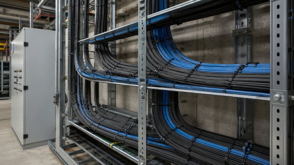
Supply Chain Complexity on Large Industrial Projects
A petrochemical plant, a utility-scale solar farm, a container port expansion — these projects routinely consume thousands of meters of control cable across 20, 30, sometimes 50-plus individual specifications. Different core counts, different conductor cross-sections (commonly 0.75 mm² through 2.5 mm² for most process control applications, though instrumentation pairs can run as small as 0.5 mm²), different shielding configurations, different outer jacket compounds for chemical or UV resistance. Sourcing that across multiple suppliers introduces version-control problems, inconsistent quality documentation, and the logistical headache of coordinating partial deliveries against a master cable schedule that the site electricians are working from in real time.
A single qualified supplier with verified production capacity, a consistent quality management system, and documented export logistics experience cuts that complexity significantly. Lead time predictability matters as much as price when a cable delivery holds up a panel build that is on the critical path.
Jinda’s Manufacturing Depth
Shandong Jinda Special Cable Group operates five production bases across China, covering roughly 470,000 m² of manufacturing space with a workforce of over 1,000 people. That scale is not incidental — it means Jinda can run multiple specifications in parallel rather than sequencing them, which keeps lead times realistic even on large, multi-specification orders. The integrated R&D, production, and QA structure means that compliance with IEC 60227, IEC 60245, UL, or a customer-specific project standard is verified internally rather than assumed.
Jinda supplies control cable customers in more than 50 countriesTrue
Stated in the company's documented profile and consistent with its export certification portfolio and logistics track record since 1987.
For projects with genuinely difficult environmental requirements — sustained low temperatures below -40 °C, continuous exposure to hydraulic fluid or H₂S-laden atmospheres, high-flex duty cycles on cable trays that move — Jinda’s engineering team develops and validates custom compound formulations in-house. That matters because outsourcing compound development to a third-party compounder adds a variable the project team cannot audit.
A Track Record Across Demanding Geographies
Supplying into more than 50 countries since 1987 has practical consequences beyond marketing language. It means Jinda has worked through the documentation requirements for Middle Eastern petrochemical projects, the third-party inspection protocols common on European renewable installations, and the port-of-entry certification requirements that catch unprepared suppliers in West Africa or Southeast Asia. The certification portfolio — and the logistical experience behind it — travels with every order.
Procurement managers, project engineers, and system integrators working with a cable schedule are welcome to contact Jinda’s technical sales team directly. Submit your specification list and Jinda will return a detailed quotation, compliance confirmation against the relevant standards, and sample availability within five business days.




