
A bad cut on industrial cable doesn’t just look unprofessional — it creates real downstream problems. Crushed or splayed conductors deform the cross-section, and even a 15–20% deformation on a large conductor can measurably increase termination resistance, which builds heat under load and quietly degrades joints until something fails at the worst possible time. On a high-current circuit that might mean a premature joint failure, an unplanned shutdown, and a termination rework job that costs far more than the right tool would have.
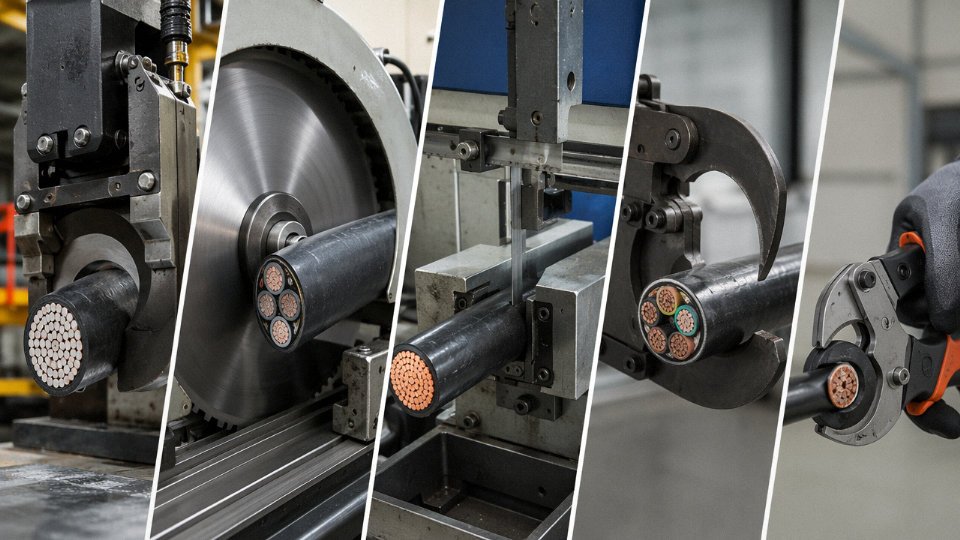
To cut industrial cable correctly, match the tool to the cable type and cross-section: manual ratchet cutters suit flexible or fine-stranded conductors up to roughly 300 mm², hydraulic cutters handle large conductors up to around 1,000 mm² in a clean single stroke, and armored cables — SWA or AWA types — require a blade hardness of at least HRC 58–62 to cut steel wire armor without damaging the tool or distorting the cut.
What most guides skip is the decision logic that sits before you even pick up a tool — conductor material, armor type, cross-section, and whether you’re working in a trench or a tight cabinet all push you toward different methods. Get that part wrong and you’re either damaging expensive cable or wearing out tooling prematurely. The sections below walk through the full process the way it actually plays out on a job site.
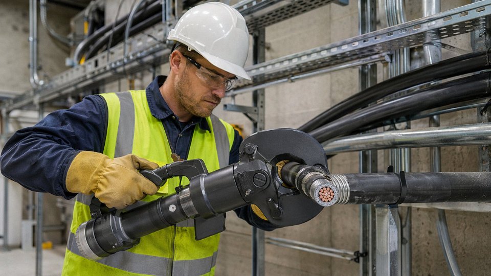
Understanding Industrial Cable Construction Before You Make the First Cut
Before you pick up a cutter, you need to know what you’re actually cutting through. This sounds obvious, but in practice a surprising number of termination failures trace back to a technician who grabbed the nearest tool without accounting for what was inside the cable jacket.
A typical industrial power cable is built in concentric layers, and each one behaves differently under a blade.
Conductors: Solid, Stranded, and Everything Between
The innermost element is the conductor — copper or aluminum, solid or stranded. Solid conductors (Class 1 per IEC 60228) are common in smaller cross-sections, fixed installations, and aluminum medium-voltage cables. They’re unforgiving under a misaligned cut: nick the conductor and you’ve created a stress concentration point that will eventually crack under thermal cycling. Stranded conductors (Classes 2 through 6) are more forgiving of slight blade misalignment, but fine-strand flexible classes (Class 5 and 6, down to individual wires of 0.2 mm or so) tend to splay and birdcage if the blade geometry isn’t right or if the cut is even slightly rushed.
Cross-section matters enormously — not just for choosing the right tool capacity, but for the cutting force profile. A 500 mm² Class 2 stranded copper conductor requires a fundamentally different approach than a 16 mm² solid aluminum one, even though both are “just conductors.”
Insulation, Screen, and Shielding Layers
Wrapped around the conductor is the primary insulation. XLPE (cross-linked polyethylene) is the standard for medium- and high-voltage cables and cuts relatively cleanly. EPR (ethylene propylene rubber) is softer and more elastic — blades tend to push and compress it rather than shear cleanly unless the tool is sharp and the cut is decisive. PVC, common in lower-voltage cables, is straightforward but can crack in cold weather; cutting PVC-insulated cables below about 0°C without warming the cable first is a good way to generate micro-cracks that won’t show up until the cable is energized.
Above the insulation you’ll often find a metallic screen — copper tape, copper wire, or an aluminum/polyester laminate — which exists to control electric field distribution and carry fault current. This layer isn’t hard to cut, but it does need to be cut, not torn. Torn screen wires curl back and can puncture the insulation during jointing if you’re not careful.
Armor: The Layer That Actually Damages Tools
Steel wire armor (SWA) and aluminum wire armor (AWA) are where most tool damage happens. Steel armor, in particular, demands blade steel with at least HRC 58–62 hardness. Softer blades deform against the wires rather than cutting them, leaving a ragged edge and usually a ruined blade.
Steel tape armor (STA) and aluminum tape armor are a different challenge — they can buckle and fold under jaw-type cutters, which then deforms the cable geometry underneath. A rotary pipe-cutter-style approach or a dedicated armor cutter is usually better for tape-armored cables.
Special Cable Types That Demand Extra Care
Mineral-insulated cables (MICC) contain compressed magnesium oxide powder around the conductors inside a copper or stainless steel tube. Cut one without sealing the end immediately and ambient moisture starts degrading the insulation resistance within minutes in humid conditions. Fire-resistant cables with mica tape layers need careful, controlled cuts — mica is brittle and any crushing fractures the tape, compromising the very property you’re paying for. Instrumentation cables with multiple fine-wire pairs inside a common screen need restraint; ratchet cutters that work fine on power cables will mangle 0.5 mm² pairs.
High-voltage cables above 35 kV have thick XLPE walls and sometimes a lead sheath under the armor. The lead is soft but it smears rather than cuts, and a serrated blade will make a mess of it.
Cross-Section, Armor, and Cutting Category Reference
| Cable Type | Typical Cross-Section Range | Common Armor Type | Cutting Category |
|---|---|---|---|
| Low-voltage power (unarmored) | 1.5 – 400 mm² | None | Manual ratchet or hydraulic |
| Low-voltage SWA/AWA power | 4 – 400 mm² | Steel or aluminum wire | Hydraulic + armor cutter |
| Medium-voltage XLPE (up to 35 kV) | 35 – 630 mm² | SWA, STA, or lead | Hydraulic, large-jaw |
| High-voltage (above 35 kV) | 95 – 1,000 mm² | Lead sheath + wire armor | Hydraulic, specialist tooling |
| MICC | 1 – 120 mm² | Copper or SS tube (IS the armor) | Rotary tube cutter, seal immediately |
| Instrumentation multipair | 0.5 – 2.5 mm² per pair | Aluminum/polyester tape | Fine-blade manual, controlled |
| Submarine/umbilical | 25 – 500 mm² (power cores) | Steel wire, sometimes double | Purpose-built hydraulic shears |
One operational warning worth repeating: outer diameter alone is a poor proxy for cutting difficulty. A 50 mm² SWA cable with 3 mm steel wires will punish an undersized cutter far more than a 240 mm² unarmored XLPE cable. The armor, not the conductor, usually defines what tooling you actually need.
Improper cable cutting can deform the conductor end by 15–20%, measurably increasing termination resistance and raising the risk of joint failure under sustained load.True
Conductor deformation from a poor cut reduces the effective contact area at the termination. Even modest increases in contact resistance generate heat under load current, accelerating insulation degradation and potentially leading to thermal failure at the joint — a well-documented failure mode in HV and MV cable terminations.
Selecting the Right Cutting Tool: Manual, Ratchet, Hydraulic, and Saw-Based Options
Picking the wrong cutter doesn’t just slow you down — it deforms the conductor, contaminates the insulation cut-face, and in the case of armored cable, can shatter a blade or kick back hard enough to injure the operator. The tool has to match the cable’s cross-section, its construction layers, the available power source, and whether you’re in a workshop or hanging off a cable tray six meters up.
Manual Scissors and Diagonal Cutters
These are fine for flexible control cables — typically up to around 50 mm², depending on stranding class and conductor material. A decent pair of forged-steel cable scissors with an induction-hardened cutting edge will handle Class 5 or Class 6 flexible copper cleanly at that range. Push past that and you’re fighting the tool: the blade deflects, the strands splay outward, and you end up with a ragged end that won’t seat properly in a lug or terminal block.
Never use diagonal cutters on any cable with steel wire armor. The geometry is wrong and the blade hardness — usually in the HRC 54–56 range on even good-quality diagonal pliers — won’t hold an edge against SWA. You’ll roll the cutting edge on the first stroke and produce a crushed, not cut, conductor end.
Ratchet Cable Cutters
The ratchet mechanism gives you mechanical advantage through a incremental pawl-and-ratchet system: each squeeze of the handle advances the blade, so you’re not trying to complete the cut in a single motion. Quality models — Knipex, Greenlee, and a handful of Asian-manufactured equivalents that have improved significantly over the past decade — handle up to 240–300 mm², though the actual practical limit depends heavily on conductor class and whether it’s copper or aluminum.
Jaw profile matters more than most buyers realize. Round-jaw heads work well on circular conductors; sector-shaped conductors (common in multi-core LV power cables) need a matching sector jaw or the conductor will rotate under blade pressure and come out oval. For field use, ratchet cutters are hard to beat — no power required, compact enough for a tool bag, and consistent enough for clean termination ends if you’re working within their rated range.
Hydraulic Cable Cutters
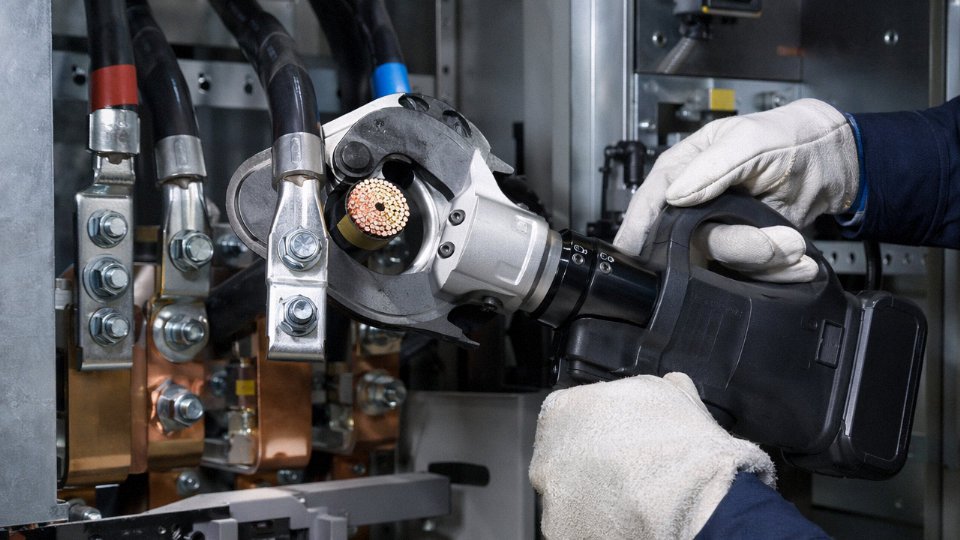
Hand-pump hydraulic cutters and battery-powered electric-hydraulic models both develop enough force to handle conductors up to 1,000 mm² in a single stroke — something no ratchet tool comes close to. Cutting force on professional-grade heads typically runs 120–180 kN depending on the model and head geometry. The rotating head (usually ±180° on quality units) is genuinely useful when you’re working in a congested cable trench or a switchgear cabinet where you can’t orient the tool in a straight line.
Hydraulic cable cutters can cleanly cut conductors up to 1,000 mm² cross-section in a single strokeTrue
Modern hydraulic cutters rated at 120–180 kN cutting force, such as those from Burndy, Greenlee, or equivalent industrial-grade brands, are designed and tested to this capacity. Single-stroke cutting at this range eliminates the conductor deformation associated with multiple-pass cutting on large cross-sections.
Battery-powered models (typically 18V or 36V platforms) suit most site work. Hose-connected hydraulic tools connected to a separate power unit make sense for sustained production-line work — offshore cable laying operations, for instance — where you’re cutting dozens of large conductors in sequence and battery endurance becomes a real constraint.
Angle Grinders with Abrasive or Carbide Discs
For armored cables in the field — SWA or AWA types where the steel wire or aluminum wire armor needs to be cut before the cable can be terminated — an angle grinder with an abrasive cutoff disc is often the practical answer. The blade hardness requirement is real: cutting steel wire armor demands HRC 58–62 minimum, and standard disc cutters meet this. What they introduce is heat, and heat is the enemy of XLPE and PVC insulation layers sitting just millimeters beneath the armor.
The practice that actually works: score the armor in short passes rather than driving through in one continuous cut, and direct the sparks away from the cable body. Some experienced cable jointers wrap the exposed insulation just below the cut line with a damp rag. It’s low-tech but it works. A full face shield and leather glove on the guide hand are non-negotiable — armor wire under a disc can fragment.
Cold Saws and Band Saws
In a workshop environment, for very large-diameter cables — think 500 mm² and above, or large submarine cable cross-sections — a cold saw or metal-cutting band saw gives the cleanest possible end face. Blade selection: 4–6 TPI for large copper conductors, moving toward 8–10 TPI for tighter-pitch cutting on smaller armored cables where you want more tooth engagement per unit length.
Clamping is the issue most shops underestimate. Without a proper clamping fixture that grips the cable on both sides of the cut and prevents the outer layers from rotating relative to the conductor during the blade pass, you’ll get conductor splay — strands fan out as the blade passes through, and the end is useless for a proper lug crimp without re-dressing.
Specialty Tools
Pipe cutters adapted for cable use work for round, unarmored cables in the 20–80 mm outer diameter range — they score and roll-cut the jacket and insulation layers without blade impact. Niche, but useful for precision jacket removal when you need a clean, controlled depth cut.
Diamond wire saws are standard on submarine cable installation vessels for cutting high-voltage submarine cable at depth or on the vessel deck. The cross-sections involved — often 500–1,000 mm² copper or aluminum conductors encased in multiple armor layers — make conventional tooling impractical. This is specialized enough that the tool choice is dictated by the cable contractor’s standard operating procedure, not field improvisation.
Tool Selection Decision Matrix
| Cable Cross-Section | Armor Type | Power Available | Site Portability | Recommended Tool |
|---|---|---|---|---|
| Up to 50 mm² | None | Any | High | Manual scissors / diagonal cutters |
| 50–300 mm² | None | None required | High | Ratchet cutter (correct jaw profile) |
| 50–300 mm² | SWA / AWA | Battery or mains | Medium | Hydraulic (battery) or angle grinder for armor layer |
| 300–1,000 mm² | None or armored | Battery or mains | Medium | Hydraulic (battery-powered electric) |
| 300–1,000 mm² | None or armored | Mains / hydraulic unit | Low (workshop) | Hydraulic (hose-connected) or cold saw |
| >500 mm², large OD | Multi-layer armor | Workshop / vessel | Fixed | Cold saw, band saw, or diamond wire saw |
In practice, most industrial sites end up with two or three tools covering the full range of cables they routinely handle. A ratchet cutter for control and medium-power cables, a battery hydraulic unit for large-cross-section power cables, and an angle grinder with proper PPE for field armor cutting — that combination handles roughly 90% of what comes up on a typical cable installation or maintenance job.
Step-by-Step Procedure for Cutting Unarmored Power and Control Cables
Unarmored cables — from 1.5 mm² control wiring up to 630 mm² or larger power conductors — represent the bulk of what most electricians and installation crews cut on any given project. The procedure below applies across that range, with notes where technique has to shift for larger cross-sections.
Step 1 — Verify De-Energization
Before anything touches the cable, confirm LOTO is in place and documented. A padlock on the breaker is not enough on its own; use a non-contact voltage tester rated at or above the system voltage — a CAT III 1000 V instrument at minimum for most LV industrial circuits — and test at both ends of the cable run if both ends are accessible. On medium-voltage cables or in substations, earthing is non-negotiable: apply a portable earth clamp to the conductor and verify it’s bonded before picking up any cutting tool. Capacitive charge on long cable runs can retain enough energy to arc badly even after disconnection.
Step 2 — Mark and Measure
Use a chalk line or permanent marker rated for cable sheathing — a light scribe on the outer jacket works fine for small cables, but on 185 mm² and above, a wrap of PVC tape as a cutting guide helps keep the blade aligned. Account for termination allowance at this stage, not after. For large power cables landing in a panel or termination box, leaving 150–300 mm extra is standard practice; the exact amount depends on lug type, conduit entry geometry, and whether the cable needs to reach a secondary disconnect point. Cutting short costs you the whole cable length in some installations. Cut long, then trim if needed.
Step 3 — Secure the Cable
Movement during cutting produces angled faces and conductor fan-out. Clamp the cable in a bench vice with soft jaw inserts, or use a saddle clamp on the cable tray if working in the field. For large-diameter cables that want to roll, wrap a couple of turns of duct tape around the jacket 50–100 mm back from the cut line to stiffen the assembly. The goal is zero rotation under cutting load — particularly important with stranded conductors, which will corkscrew if the cable body moves.
Step 4 — Choose Blade Position
Center the cutter jaw so the blade bisects the cable’s true centerline. Offset pressure — even 5–10 mm off-center on a 300 mm² conductor — causes the blade to deflect during stroke, fanning the outer strands outward and compressing the inner ones. The result is a cut face that looks almost right but isn’t: conductor deformation in that range can increase termination resistance measurably, and under repeated load cycling a poorly formed lug crimp on a deformed end will eventually loosen.
Step 5 — Execute the Cut
On a hydraulic cutter, one smooth, continuous stroke is the target. Stopping mid-stroke and releasing pressure partially is the single most common mistake — it work-hardens the outer strands and forces you to reposition, almost always making the cut face worse. With a ratchet cutter, cycle steadily without reversing the mechanism; reversing loosens the jaw and lets the cable shift. For cables above roughly 240 mm², a battery hydraulic unit (Cembre, Burndy, or similar) makes this step fast and consistent in a way that a manual ratchet simply cannot match at the end of a long shift.
Step 6 — Inspect the Cut Face
A good cut face is square within about 3° of perpendicular — check it visually and, on critical terminations, with a small square or protractor. The insulation edge should be clean with no cracking or crazing; PVC jackets sometimes chip in cold weather, which is a seasonal issue worth noting if you’re doing outdoor work below 5 °C. Look for copper or aluminum burrs on the conductor perimeter. Any burr left in place will eventually work through insulation under vibration.
Improper cable cutting can cause conductor deformation of 15–20%, increasing termination resistance and risking joint failure under sustained load.True
Off-center or interrupted cuts compress inner strands and fan outer ones. The resulting non-uniform crimp contact area raises resistance at the termination, which worsens under thermal cycling and can lead to joint failure over time — a well-documented failure mode in cable termination literature and field investigations.
Step 7 — Dress and Prepare the End
Don’t leave a freshly cut cable end open. Moisture wicks into stranded conductors within minutes in humid plant environments, and copper oxide on the strand surfaces will degrade crimp quality when you terminate days or weeks later. Apply a heat-shrink end seal, a push-on end cap, or at minimum several tight wraps of self-amalgamating tape immediately after inspection. For aluminum conductors, this step is more urgent — aluminum oxidizes faster and the oxide layer is harder to break through during crimping. If the cable is going into storage before installation, label the end with the circuit reference at the same time. Future-you, or whoever terminates the cable next month, will be grateful.
Cutting Armored Cables: SWA, AWA, and Steel Tape Armor Without Damaging Inner Layers
Armored cable is where a lot of installers get into trouble. The armor exists to protect the cable in service, and that same toughness works directly against you when you’re trying to cut it cleanly. Standard cable cutters — even decent ratchet models — frequently fail on SWA. Here’s why: each individual steel wire in a typical SWA construction carries tensile strength in the range of 500–700 MPa, and when you have 30-plus wires sitting in a helical bundle, their collective resistance to compression is substantial. A blade that isn’t hard enough (below HRC 58, roughly) won’t shear the wires so much as squeeze them, causing the bundle to deform laterally. What happens next is the real problem — compressed wires spring outward unpredictably, and a sprung wire end can easily puncture the bedding layer or inner sheath beneath. You then have insulation damage you can’t see until the cable fails under load.
Industrial armored cable cutting requires blade hardness of at least HRC 58–62 to shear steel wire armor cleanly without tool damage or wire spring-back.True
Steel wire armor on SWA cables typically has tensile strength of 500–700 MPa. Blades below HRC 58 deform rather than shear the wires, causing lateral spring-back and potential insulation puncture.
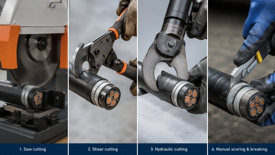
Method 1 — Dedicated Armored Cutter or Heavy Hydraulic Cutter
A purpose-built armored cable cutter differs from a standard hydraulic cutter in jaw geometry. Standard cutters use relatively straight opposing blades optimized for copper or aluminum conductor; armored cable cutters use a curved or profiled jaw that wraps partially around the cable circumference, distributing force more evenly and driving wires inward toward the cut rather than sideways. For a 4-core 240 mm² SWA cable — a size you see constantly in UK industrial installations and increasingly in export projects — expect to need 32–40 kN of closing force for a clean single-pass cut. That’s at the upper end of most battery-hydraulic tools; verify your tool’s rating before you assume it’s adequate.
Single-pass cutting is always preferable. Sequential wire cutting — going around the cable snipping individual wires with side cutters — is slow, leaves uneven wire lengths, and almost always results in at least a few wires being bent rather than cut.
Method 2 — Angle Grinder with Cutting Disc
For large-diameter SWA or steel tape armor (STA) cables where no hydraulic cutter is available, an angle grinder with a thin metal cutting disc (1–1.6 mm) works well if you’re disciplined about depth. The technique is to score the armor circumferentially — rotating the cable or walking the grinder around it — to a depth that severs the armor layer without contacting the inner sheath. On STA specifically, scoring about 80% through the tape thickness and then bending sharply will snap the tape cleanly. Keep disc RPM within the manufacturer’s rated limit for the disc diameter; over-speeding a worn disc on steel generates heat that can soften the bedding compound directly beneath.
Mark your cut line with tape first. It sounds obvious but in a cable drum yard at 6 AM it isn’t.
Method 3 — Armored Cable Stripping Tool as Pre-Cut Aid
Removing the outer PVC oversheath before attempting to cut the armor layer gives you two real advantages: you can seat the cutter blade directly against the armor surface without the oversheath causing blade skew, and you can visually inspect the armor condition before cutting. A rotary stripping tool set to oversheath depth only — not armor depth — handles this in under a minute on most cable sizes.
Post-Cut Armor Dressing
A cut armor end is sharp in ways that are genuinely dangerous to handle and to the cable itself. File individual wire ends or tape ends flush, then bend back and trim the wires to the correct gland entry length for your specific gland model — this varies, but 15–25 mm exposed armor is typical for most industrial compression glands. Exposed steel armor on cut ends should receive an anti-corrosion treatment, either a proprietary zinc-rich compound or at minimum a wrap of self-amalgamating tape, especially in outdoor or humid environments.
Aluminum Wire Armor — AWA Specifics
AWA feels easier to cut than SWA, and it is — aluminum is significantly softer. The catch is work-hardening. AWA wires harden rapidly under repeated tool pressure, so if your first cut attempt doesn’t go clean and you reposition, the second pass is cutting partially work-hardened material. Single-pass commitment matters here. Prefer cutter jaws with a polished or chrome-plated contact surface; aluminum has a tendency to cold-weld to rougher tool steel, which tears rather than shears the wire and leaves a ragged end.
Quality Check Before You Terminate
Before any gland goes on, measure the armor cut position relative to where the core insulation ends. The typical allowable tolerance for standard industrial cable glands is ±5 mm — tighter than most people assume. Outside that range, either the armor won’t seat properly in the gland cone, or you’ll have exposed armor wires sitting against core insulation under clamping pressure. Neither outcome is acceptable on a cable that’s going into a distribution board or motor starter.
The allowable tolerance for armor cut position relative to the core insulation end is typically ±5 mm for standard industrial cable glands.True
Standard industrial compression glands are designed with a specific armor engagement depth. Cuts outside ±5 mm tolerance result in either incomplete armor clamping or armor wires contacting core insulation under gland pressure, both creating termination failure risk.
Take thirty seconds and check it with a steel rule before assembly. Redressing an armor end is a few minutes of work. Discovering a failed termination under load is a much worse conversation.
Safety Protocols and PPE Requirements When Cutting Industrial Cables on Live or Recently Live Systems
The single most important thing to accept before picking up any cutting tool: you should never be cutting a live cable. Full stop. Every regulatory framework — IEC 60900, NFPA 70E, EN 50110 — converges on the same baseline. De-energize, verify, earth. In that order, every time, regardless of schedule pressure.
Regulatory Baseline and the “Verified Dead” Requirement
IEC 60900 governs insulated hand tools for live working, and it’s worth reading carefully — because it also makes clear that live working is a controlled exception, not a routine option. NFPA 70E establishes arc flash boundaries and incident energy thresholds that determine how close anyone can stand to exposed conductors at various voltage levels. EN 50110 covers operation of electrical installations across European jurisdictions and explicitly requires a formal “five safety rules” sequence before any work on cables.
The practical point: if you’re cutting cable on an active industrial site where adjacent circuits may be energized, arc flash boundaries still apply even when your specific cable is isolated. A slip of a hydraulic cutter near a live bus can release incident energy fast enough to cause third-degree burns before a person can react.
Cutting should always occur on de-energized, verified, and earthed cablesTrue
IEC 60900, NFPA 70E, and EN 50110 all require de-energization, verification of absence of voltage, and earthing before cable cutting work proceeds. Live cutting is a controlled exception requiring specific authorization and elevated PPE, not standard practice.
PPE Minimums by Voltage Class
For low-voltage work (up to 1,000 V AC), the minimum is IEC 60903 Class 00 gloves (rated 500 V) for incidental exposure; Class 0 (1,000 V) is a more practical baseline for cable cutting near LV panels. Medium-voltage cable work — typically 3.3 kV to 33 kV — requires Class 2 or Class 3 gloves (rated 17,000 V and 26,500 V respectively). Class 4 gloves, rated to 36,000 V, are needed for HV cables above 30 kV.
Arc flash-rated face protection: 8 cal/cm² minimum for most LV switching environments; MV cable cutting in enclosed switchrooms can easily demand 25–40 cal/cm² depending on the incident energy calculation for that specific panel. Flame-resistant (FR) clothing rated to NFPA 70E HRC 2 or above, safety boots with EH (electrical hazard) rating per ASTM F2413, and hearing protection if using abrasive cut-off saws are all non-negotiable.
LOTO Specific to Cable Cutting
Lockout/tagout for cable work has a few wrinkles that general electrical LOTO sometimes glosses over. First, identify every isolation point — cables in industrial plants often have multiple feed sources, including UPS backfeeds and generator ties that are easy to miss on an outdated single-line diagram. Padlock every isolation point yourself; don’t rely on someone else’s lock.
For capacitive cables — particularly HV XLPE cables over roughly 10 kV and any cable longer than a few hundred meters — allow an energy dissipation wait time before cutting. A 33 kV cable that has been isolated can retain enough charge to cause a serious flash if cut immediately. Industry practice is typically 5–15 minutes depending on cable length and capacitance, verified with a calibrated voltage detector rated for that voltage class. Two-person verification is not optional; one person calls out the meter reading, the second confirms it.
Hazards Specific to the Cutting Operation Itself
Armor wire rebound is genuinely dangerous and underestimated. Steel wire armor under tension in a tight conduit or tray can spring back sharply when severed — wire fragments at eye level are a real risk. Always wear a face shield, not just safety glasses, when cutting SWA or AWA cables.
Copper and aluminum conductor shards from hydraulic or ratchet cutters project with surprising force, particularly from large cross-section conductors (240 mm² and above). A partial conductor cut that slips can send a fragment several meters. Keep bystanders clear.
If cutting PVC-insulated cable with an angle grinder or abrasive saw — which should honestly be a last resort — friction heat releases hydrogen chloride gas and plasticizer fumes. Fluoropolymer insulations (PTFE, FEP) are worse; above roughly 260°C they off-gas compounds that cause polymer fume fever. Cutting PVC or fluoropolymer insulation mechanically rather than thermally is the correct approach. If you’re in a confined space — a cable trench, a basement cable cellar, a duct bank access pit — forced ventilation is required before and throughout the operation, and a gas monitor for both oxygen level and HCl concentration should be running. The buddy system in confined spaces is both a regulatory requirement under most jurisdictions and plain common sense.
Non-sparking tools (bronze or beryllium copper alloy blades and handles) are required where flammable atmospheres are possible — fuel gas infrastructure, chemical plants, offshore facilities. Standard steel cable cutters are not suitable in those environments.
First Aid Preparedness
Have a burn treatment protocol in place before starting, not after an incident. Armor wire puncture wounds are particularly nasty — steel wire armor is not clean, and puncture depth can be deceptive given the force of a rebound. Wounds should be cleaned thoroughly and assessed for depth before anyone assumes it’s minor. An eyewash station must be within 10 seconds of travel from the cutting location per ANSI Z358.1; if the work location doesn’t meet that, bring a portable eyewash bottle rated for the task.
Documentation That Actually Gets Done
Every cable cut should be logged in the cable schedule with the actual cut length, the date, and the technician’s name. As-built drawings need to reflect any change to cable routing or termination point resulting from a re-cut. The permit-to-work closure checklist — signed off by both the issuing authority and the performing technician — is what formally returns the circuit to service. Skipping that closure step is how circuits get re-energized before a second crew has finished working on them.
Maintaining Cut Quality: Blade Care, Calibration, and When to Replace Cutting Tools
Tool maintenance is where professional cable work separates from field improvisation. A sharp, correctly calibrated cutter is the difference between a termination that holds for 30 years and one that develops a hot joint inside 18 months. Most cable damage at cut ends isn’t caused by wrong tool selection — it’s caused by the right tool being in the wrong condition.
Reading Blade Wear Before It Reads You
Inspect cutting blades under good light before every shift when cutting volume is high, or at minimum weekly during lower-intensity work. The failure modes to look for are chipping along the cutting edge (visible as small notches that leave ragged conductor strands), rounding of the blade tip (which requires increasing force to initiate the cut, causing the conductor bundle to deform radially before the blade engages), and asymmetric wear on one side of the jaw. That last one is insidious — the cut still completes, but the conductor cross-section becomes egg-shaped rather than round, and you won’t always catch it without a quick check with a micrometer across the end. Conductor deformation of 15–20% is enough to increase termination resistance noticeably and invite joint failure under sustained load.
Asymmetric blade wear causes conductor deformation that increases termination resistance and can lead to joint failure under load.True
Uneven wear means the blade approaches the conductor axis off-center, applying lateral force that distorts the conductor bundle. The resulting non-circular conductor end creates uneven contact pressure inside compression lugs and push-fit terminals, raising resistance at the joint.
Replacement Blade Standards — Don’t Cut Corners Here
Replacement blades for industrial ratchet and hydraulic cutters should be Cr-Mo alloy tool steel, hardened to HRC 58–62. For armored cable work — SWA, AWA, steel tape — that lower bound of HRC 58 is not negotiable; softer blades will roll at the edge on the first few cuts and are effectively destroyed before they look worn. Generic replacement blades from unverified sources often come in at HRC 52–55, which feels adequate on the first pass but degrades quickly and starts deforming cable ends within a few hundred cycles. In practice, the cost of re-stripping and re-cutting a 240 mm² cable because a cheap blade crushed the conductor end — losing roughly 300–500 mm of material per incident — quickly dwarfs any savings on the blade itself. On a project with several hundred terminations, this adds up to real scrap cost and schedule slippage.
Hydraulic Cutter Service
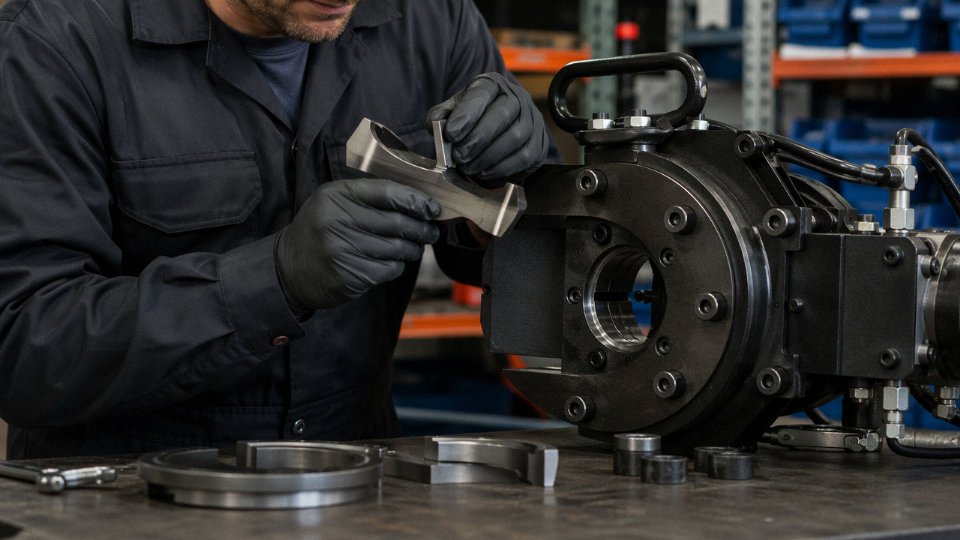
Hydraulic cutters require checks that go beyond the blade. Check hydraulic fluid level and viscosity at least monthly under regular use; low fluid causes the cylinder to cavitate and the cutting stroke to hesitate mid-cut, which is exactly how you get a partially crushed conductor. Fluid viscosity matters seasonally — a fluid rated for a 5–40°C range will behave sluggishly below 10°C and may cause incomplete strokes on large-format conductors in winter site conditions. Inspect hose connections and cylinder seals for micro-leaks at every use; a weeping seal that loses 0.5 bar per stroke will underperform on large conductors even if everything else looks fine. Verify pressure calibration against the tool’s rated cutting force specification at least quarterly using a calibrated gauge adaptor — most manufacturers publish the rated pressure range in the tool documentation.
Ratchet Mechanism Service
After armored cable work, clean the pawl and gear teeth immediately. Steel wire fragments and aluminum armor dust pack into the ratchet mechanism and accelerate wear on the engagement teeth, eventually causing the ratchet to slip under load — which is both a cut-quality problem and a hand-injury hazard. Lubricate with a light machine oil (not grease, which traps debris) every 50–100 operating cycles depending on how dirty the environment is, and check spring tension by feel: the ratchet should advance crisply with no back-slip. A pawl spring that’s lost tension gives a soft, spongy advance that’s easy to ignore until the mechanism fails mid-cut.
Calibration Records and Tool Tagging
Implement a color-code inspection tag system on a quarterly cycle — a common approach uses four colors rotated across Q1 through Q4, so any tool missing the current quarter’s tag is immediately visible as uninspected. Log cut quality observations (conductor roundness, clean shear vs. crush) against the tool’s serial number, not just its type. This lets you spot a specific unit that’s producing deformed ends before the problem becomes systemic. Out-of-tolerance or suspect tools should be physically removed from the job site kit, not just set aside. Tape over them, tag them “QUARANTINE — DO NOT USE,” and route them for regrind or replacement.
Storage
Blade covers are not optional on stored hydraulic cutters — exposed blades nick each other in a tool bag and develop rust pits that act as stress concentrators during cutting. Apply a light anti-corrosion film to all metal blade surfaces before storage, especially for tools going into outdoor site containers where humidity cycles are wide. Battery-powered hydraulic cutters typically have operating temperature limits in the range of −10°C to 50°C; storing them below that lower bound risks seal contraction and cell damage. Keep them in a heated store room over winter if the site gets cold, or expect shortened battery life and unpredictable seal behavior in spring.
Cable Cutting in Large-Scale Industrial and Infrastructure Projects: Procurement and Logistics Considerations
Large projects don’t fail on a single bad cut. They fail when hundreds of cuts accumulate small errors — wrong lengths, wasted drum remnants, mislabeled runs — until the rework cost quietly exceeds the original cable budget. At project scale, cutting quality is inseparable from procurement planning.
Cut-Length Planning from the Cable Schedule
The cable schedule is where waste is either locked in or engineered out. Before ordering a single drum, pull every route length from the engineering drawings, add your installation allowances (typically 1–2 m at each termination end, more for MV joints), then sort routes by cable type and cross-section. Group routes that share the same cable specification into drum assignments that use each drum close to its full length. On a well-planned project, the waste factor — offcuts too short to use elsewhere — should stay below 3–5% of total cable volume. Getting below 3% usually requires software-based cut optimization, which most medium-to-large EPC contractors now run as a matter of course. Projects that skip this step and just order round numbers routinely land at 10–15% waste, which on a 500-tonne cable package is real money.
Drum Length Coordination with the Manufacturer
Standard catalogue drum lengths rarely match what a project actually needs. Jinda supplies non-standard drum lengths from 100 m coils — useful for short instrument cable runs where you’d otherwise cut from a 500 m drum and shelve most of it — up to 2,000 m or longer for continuous LV feeder runs where a single pull demands it. Aligning drum lengths to the cut schedule before manufacture is the single highest-leverage conversation a procurement manager can have with a cable supplier. It compresses on-site cutting volume, reduces handling time, and shrinks the remnant pile.
Factory Testing and Cut-Point Marking
Cables shipped with factory test certificates — drum resistance, insulation resistance, high-voltage test results — allow site teams to trust the delivered product and focus effort on installation rather than remedial testing. Where Jinda marks sequential length references on the outer jacket during extrusion, on-site measurement error drops substantially; teams aren’t unrolling 300 m of cable to guess where 147 m falls. That sounds minor until you’ve watched a crew spend 40 minutes on a measurement that a factory ink mark would have resolved in 30 seconds.
Setting Up a Dedicated On-Site Cutting Station
For projects with significant cable volumes, a fixed cutting bay pays back quickly. The basic setup: a powered drum stand or unreeling cradle to control tension, a fixed hydraulic cutter station mounted to a work bench or structural frame for cables up to 400 mm² or larger, and a clear staging area for coiled cut lengths awaiting tagging. A reasonably organized station with two operators — one unreeling, one cutting and tagging — can process roughly 60–80 cuts per shift on cables up to 400 mm². That figure drops on armored types or larger cross-sections where repositioning takes longer.
Material Traceability After Cutting
Every cut length needs a drum number, a cut sequence identifier, and the installed route designation before it leaves the cutting station. Heat-shrink markers last; adhesive labels on cable jacket in hot or wet environments do not. UV-resistant cable ties with insert labels are a reasonable field compromise. This traceability matters when a termination fails six months into commissioning and you need to trace back to the original drum test certificate.
International Project Logistics
Jinda’s five production bases across China support multi-origin shipping schedules where parallel production reduces lead times on large or urgent packages. Export packaging follows IEC drum standards — drum dimensions, end-seal method, and moisture protection suited for sea freight — and cable specifications can be produced to BS 6724, IEC 60502, ASTM, or AS/NZS 1cables requirements depending on the destination country. For projects spanning multiple standards (a refinery with Australian main plant and IEC instrumentation spec, for instance), having a single manufacturer who can produce both from the same supply chain simplifies the certificate trail significantly.
Jinda Cable supplies non-standard drum lengths and exports to more than 50 countries with certificates conforming to IEC, BS, ASTM, and AS/NZS standards.True
This reflects Jinda's published manufacturing capabilities and international supply scope across five production bases in China, serving global infrastructure and industrial projects.
Surplus Cable Management
Cut remnants shorter than one standard installation run are worth keeping only if they’re properly end-sealed and catalogued. Unsealed cut ends in outdoor storage absorb moisture and degrade — a drum that looked fine at delivery fails insulation tests a year later because nobody capped the end. Recoiling remnants onto smaller reels, sealing both ends with heat-shrink end caps, and logging the residual length against the cable specification takes maybe 10 minutes per remnant but saves the cost of a replacement length. The economic reorder threshold depends on remnant length versus the minimum drum your supplier will pack — for most LV power cable specifications, remnants below roughly 20–30 m are usually consumable scrap rather than stock. For anything above that, keep it, tag it, and enter it in the project material register.
Frequently Asked Questions About Industrial Cable Cutting
Can I use a standard angle grinder to cut a 240 mm² XLPE armored cable?
Technically yes — a 115 mm or 125 mm angle grinder fitted with a 1.0–1.6 mm thin cutting disc rated for steel will get through SWA armor and conductor. In practice, though, the heat generated near the cut face partially melts XLPE insulation within 5–10 mm of the end, and the conductor strands splay badly enough that you spend significant time re-forming the end before fitting a compression lug. If the cable is being cut to a discard length and you just need it out of the way, a grinder is fine. For any termination end, a hydraulic cutter produces a cleaner, cooler, tighter cut in roughly a tenth of the time. The grinder also throws sparks across the drum — not ideal in a cable basement or tray environment with other insulated conductors nearby. Use it as a last resort in the field, not as standard practice.
How do I cut mineral-insulated cable (MICC) without cracking the magnesium oxide insulation?
MICC is unforgiving. The MgO powder compresses and seals under the copper sheath, and any lateral shock or blade rocking cracks the insulation column — sometimes invisibly, showing up only as a failed insulation resistance test later. Use a fine-tooth hacksaw (32 TPI minimum) clamped square in a vice, sawing with light, even strokes perpendicular to the cable axis. Dedicated MICC rotary tube cutters are better still; they score and snap the outer copper sheath cleanly without the vibration of a reciprocating blade. Immediately after cutting, seal the end with a temporary MICC end seal cap — even 20–30 minutes of exposure to ambient humidity is enough to absorb moisture into the MgO, driving up insulation resistance readings and potentially causing nuisance trips after commissioning.
What is the minimum blade rating I need for 630 mm² copper conductor?
Cutting force scales with conductor cross-section and stranding class. A 630 mm² Class 2 stranded copper conductor typically requires somewhere in the range of 55–70 kN depending on conductor compaction and strand count. A 60 kN hydraulic cutter is the practical minimum; 100 kN is more comfortable and gives you margin for Class 5 flexible stranding, which work-hardens slightly differently. Check the tool’s rated cross-section chart against actual conductor class — a cutter rated “630 mm²” for Class 2 may stall or deform on a fine-stranded Class 5 equivalent.
A 60 kN hydraulic cutter is sufficient for 630 mm² Class 2 stranded copper conductor under normal conditionsTrue
Cutting force requirements for 630 mm² Class 2 copper fall within the 55–70 kN range based on standard conductor geometry; a 60 kN tool covers this with minimal margin, while 100 kN provides comfortable clearance for flexible stranding classes.
How much extra length should I leave when cutting cable for a termination?
For small control cables (1.5–6 mm²), 150–200 mm of allowance past the intended termination point is usually enough. On 95–240 mm² medium-voltage cables, most experienced termination crews want 300–400 mm — enough to re-cut if the first end gets damaged, and enough reach to dress the gland without forcing bends tighter than the cable’s minimum bend radius. HV cables above 11 kV, especially those with heat-shrink or cold-shrink joints, can need 400–500 mm or more depending on the accessory manufacturer’s installation sequence. The honest answer is: read the joint kit instructions before you cut, not after.
Is it safe to cut a cable that has been de-energized but not earthed?
No. HV cables — particularly XLPE cables over 11 kV with significant capacitance — retain charge after de-energization. The discharge from a 132 kV cable can be fatal. De-energizing and locking out is necessary but not sufficient; earthing and short-circuiting the conductor at both ends of the isolated section is mandatory before any tool touches the cable. This is not a cautious interpretation — it is the requirement under IEC 60900 and most national LOTO regulations. In practice, some technicians treat earthing as optional on “small” MV cables. That thinking is what ends careers.
Can aluminum conductors be cut with the same tools used for copper?
The tools are compatible but the technique differs. Aluminum work-hardens faster than copper if the blade stalls mid-cut, which deforms the conductor and makes lug fitting difficult. Aluminum also has a lower shear strength, so you actually need slightly less force than copper for the same cross-section — roughly 60–70% of the copper figure, depending on alloy grade. That sounds easier, but the bigger risk with aluminum is blade geometry: a blade designed for copper has a sharper, more aggressive profile that can cause aluminum strands to grab and bunch rather than shear cleanly. Some hydraulic cutter manufacturers offer aluminum-profile blades with a wider included angle; worth having on hand if you’re cutting large-format aluminum conductors regularly.
How do Jinda’s cables compare in terms of cutting difficulty due to conductor construction?
Jinda manufactures conductors to IEC 60228 Class 1, 2, and 5 depending on the cable type, with compacted round or sector-shaped conductors available for power cable ranges. Compacted conductors cut noticeably cleaner than equivalent non-compacted designs — the strands don’t splay on tool contact, which matters when you’re cutting in a confined tray or trench with limited room to clean up the end afterward. Consistent lay pitch and conductor diameter tolerances across a production batch mean the cutting force you set up for at the start of a drum stays predictable through the last cut. On bulk infrastructure projects where a single contract might involve hundreds of cuts across multiple cable sizes, that consistency reduces tool adjustment stops and rework. It’s one of those manufacturing details that doesn’t appear on a data sheet but makes a real difference on site.



