Pulling an unmarked cable out of a conduit and guessing its rating has ended more than a few maintenance shifts in an unplanned outage. Wrong insulation type on a high-temperature run, misread conductor sizing on a power feed, a color code interpreted under one regional standard when the installation followed another — any of these turns a routine splice or replacement job into a scrap pile, a tripped breaker, or in the worst case, a fire. The financial sting comes fast: emergency re-pulls on a factory floor can run into thousands in labor and downtime before you even price the replacement cable.
To identify a cable type, read the jacket print legend first — it carries voltage rating, insulation material, conductor size (AWG or mm²), and standards compliance. Then confirm conductor color coding against the applicable regional standard (NEC, IEC 60446, or AS/NZS 3000). For unmarked or aged cable, use a wire gauge tool or micrometer on the bare conductor, check jacket flexibility and temperature rating by material, and cross-reference any visible certifications against your local code.
What makes this harder in practice is that a single facility often has cables sourced from three different eras and two different continents sitting in the same tray, each marked — or not marked — according to different conventions. The rest of this guide works through every reliable identification method, in the order you’d actually use them on a real plant floor.
Reading the Jacket Print Line: Decoding Every Marking on a Cable Surface
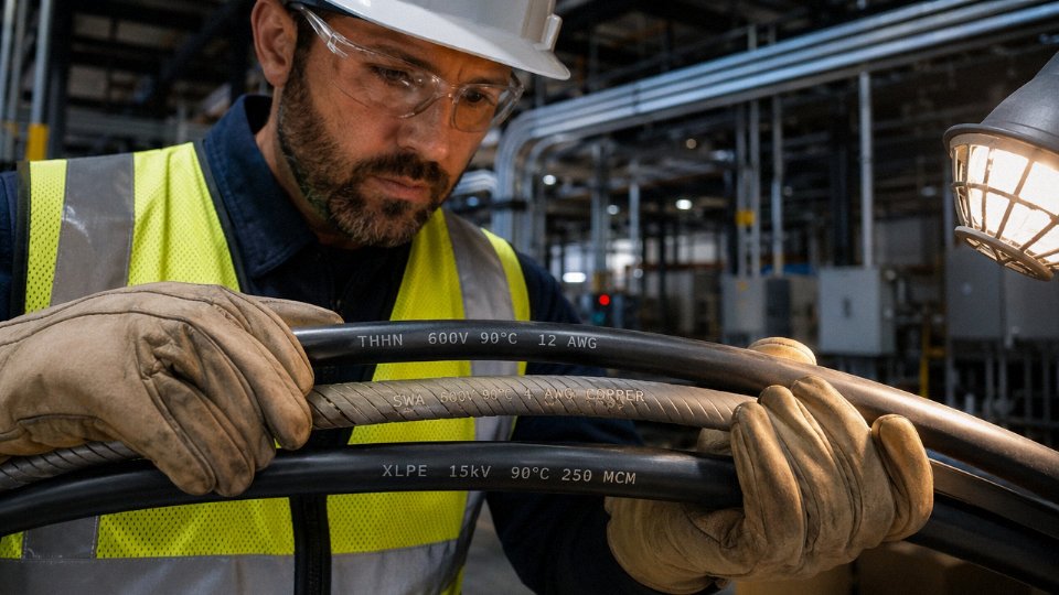
The outer jacket of any manufactured cable is essentially a data label wrapped around the conductor — and most people walk right past it. Before you reach for a multimeter or start cutting into insulation, spend thirty seconds reading what’s already printed on the surface. In the majority of cases, the print line gives you everything: wire type, voltage class, conductor count, size, and the standards it was built to.
What a Full Print Line Actually Contains
A properly marked cable jacket carries information in a fairly consistent sequence, though the exact order varies by standard and manufacturer. Reading left to right, you typically encounter: the manufacturer name or trademark, country of origin, the cable designation code (this is the critical part), conductor count and cross-sectional area or AWG size, voltage rating, applicable listing marks or certification symbols (UL, CSA, CE, CCC), and then repeating sequential footage or meter markers. Those distance markers — printed every 30 cm to 1 m depending on the spec — serve as a reel-length verification tool, not just decoration. If your cut piece shows “450” and “500,” you have roughly 50 m of cable, give or take the cut points.
Decoding North American Designations
North American cables follow NEC-referenced type designations where every letter and number carries a specific meaning. Take THHN: T = thermoplastic insulation, H = rated for 75°C, the second H = 90°C dry rating, N = nylon jacket. THWN-2 adds W (wet locations rated) and the “-2” suffix confirming the 90°C wet rating under UL 83. XHHW-2 swaps in X for cross-linked polyethylene insulation — harder, more abrasion-resistant, and suited to conduit pulls where THHN might get nicked. NM-B is nonmetallic sheathed cable, the residential workhorse; the B suffix means the grounds run at the same insulation temperature class as the conductors. MC is metal-clad armored cable. USE-2 means Underground Service Entrance rated, 90°C.
| Code | Insulation | Temp Rating | Key Use |
|---|---|---|---|
| THHN | PVC + nylon | 90°C dry | Conduit wiring |
| THWN-2 | PVC + nylon | 90°C wet/dry | Wet conduit, outdoor |
| XHHW-2 | XLPE | 90°C wet/dry | High-pull conduit runs |
| NM-B | PVC | 90°C | Residential in-wall |
| USE-2 | XLPE or HDPE | 90°C | Direct burial, service entry |
IEC and European Harmonized Codes
European cables follow the HD 361 harmonized designation system, and once you understand the structure it reads almost like a sentence. The leading “H” means harmonized (recognized across EU member states); a national prefix like “A” means nationally approved. The voltage designation follows — 07 means 300/500 V, 1 means 450/750 V. Then insulation material: R = natural rubber, V = PVC, X = cross-linked. Conductor and sheath codes trail behind. So H07RN-F: harmonized, 450/750 V, rubber insulated, neoprene sheath, flexible stranded — a classic portable equipment cable. ÖLFLEX is a registered Lapp brand trade name, not a designation code, though the jacket print will include the actual H-code alongside it.
For fixed-installation power cables, NYY means PVC-insulated, PVC-sheathed; N2XY replaces the inner PVC with XLPE and is roughly equivalent to IEC 60502 construction. NAYY is the aluminum conductor variant of NYY.
Chinese GB Codes on Jinda Products
Buyers importing cables made to Chinese GB standards will encounter a parallel designation system. YJV = XLPE insulated, PVC sheathed — the GB equivalent of N2XY in most respects. VV is the all-PVC version. YJLV substitutes aluminum conductors (the L). KVV is a PVC control cable. ZR- as a prefix means flame-retardant; NH- means fire-resistant (maintains circuit integrity under flame for a rated period, which is a meaningful difference in emergency systems). For international procurement, requesting the IEC cross-reference from your supplier is routine and any serious manufacturer will provide it without hesitation.
Chinese GB standard YJV cable is functionally equivalent to IEC N2XY in conductor and insulation construction for most power distribution applicationsTrue
Both use XLPE insulation over copper conductors with a PVC outer sheath and are designed to IEC 60502-equivalent performance levels, though specific mechanical and test requirements may differ between GB/T 12706 and IEC 60502 — always verify the test reports for critical installations.
When the Print Line Is Worn or Missing
Cables stored outdoors, buried, or pulled through abrasive conduit sometimes arrive with the jacket print largely gone. Before you break out the wire gauge and start guessing, try one thing first: photograph the jacket under raking light — hold your phone flashlight nearly parallel to the surface rather than shining it straight on. Indented or embossed characters that are completely invisible under flat lighting will often pop into legibility. Faded ink sometimes reads clearly if you slightly overexpose the shot and zoom in on the image. This takes about ninety seconds and has saved many a destructive inspection.
If the print line is genuinely absent or illegible, the next steps move into physical cross-section measurement, insulation resistance testing, and conductor material identification — covered in the following sections.
Physical Construction Clues: Identifying Cable Type by Dissection and Visual Inspection
When the jacket print line is worn off, overprinted, or simply missing — and this happens more often than it should, especially on older site stock or reeled cable that’s been stored outdoors — physical dissection is your next reliable method. Done carefully, it tells you nearly everything you need to know.
Safety Before You Touch Anything
Even on a cable sample sitting on a workbench, follow lockout/tagout. Cut ends can retain charge in capacitive systems, and in any plant environment you can’t always guarantee what’s actually de-energized. Wear insulated gloves rated for the expected system voltage, use a proper cable knife rather than a box cutter (the controlled-depth blade matters), and wear safety glasses — armor wire under tension springs. This is not a step to abbreviate.
What the Outer Jacket Is Telling You
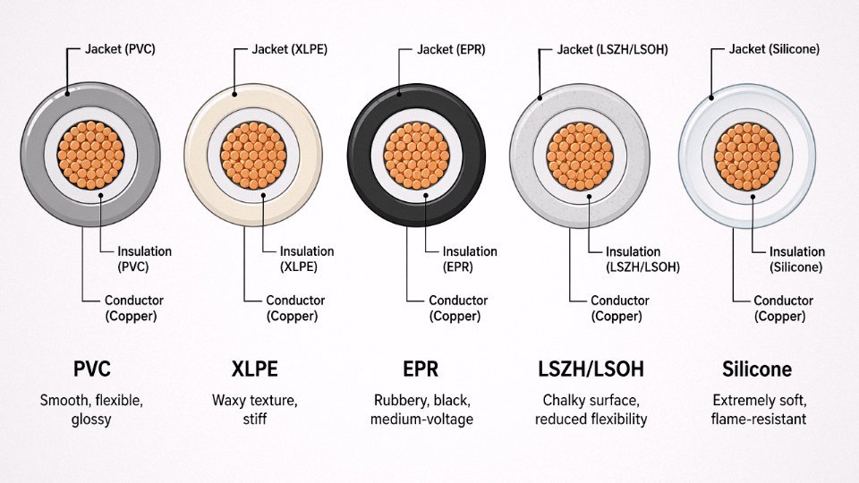
Run a gloved hand along the jacket surface before you cut anything. Standard PVC feels smooth, slightly glossy, and bends easily in your hand. XLPE has a faintly waxy texture and noticeably more stiffness — you’ll feel it trying to hold its coiled shape. EPR is distinctly rubbery and almost always black; it’s common on medium-voltage mining and offshore cable. LSZH/LSOH has a chalky, almost powdery surface and reduced flexibility that makes it creak slightly when bent sharply in cold conditions — relevant if you’re working in a warehouse in January. Silicone jacket is unmistakably soft, almost like a gel sleeve, and it will char briefly and self-extinguish rather than melt when you touch a flame to the cut end.
Identifying the Armor Layer
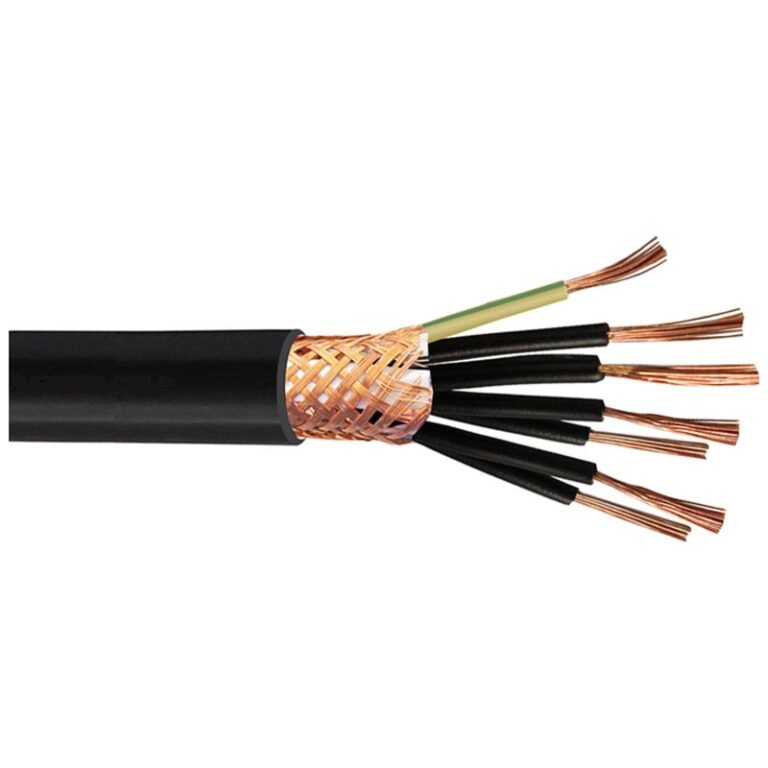
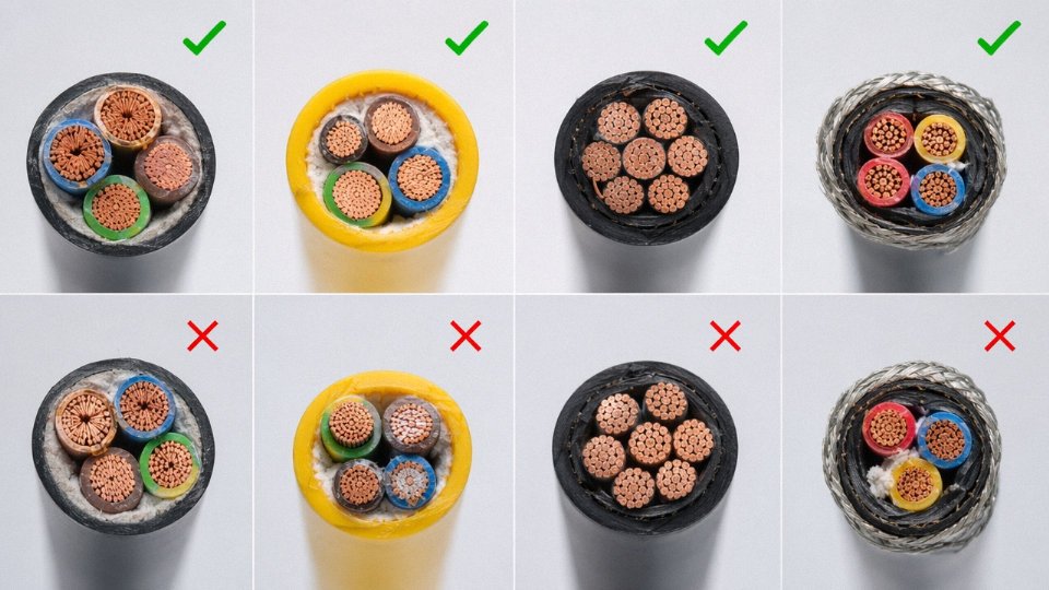
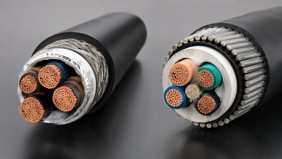
Cut through the jacket with a longitudinal slit and peel it back. Steel wire armor (SWA) presents as a helical wrap of round wires; bring a small magnet — they’ll grab firmly. Steel tape armor (STA) looks like overlapping flat strips, also magnetic. Aluminum wire armor (AWA) is visually similar to SWA but silver-colored and non-magnetic, and the individual wires feel lighter and slightly softer. Wire braid, common on flexible control and instrumentation cables, is woven in a distinctive crosshatch and usually finer gauge. The distinction matters operationally: SWA and AWA provide mechanical protection, but AWA is the correct choice where stray magnetic fields in the armor would cause eddy current heating — a real concern on large single-core power cables.
Screens and Shields
Peel back any bedding tape underneath the armor. A copper tape screen wraps helically and unrolls in a continuous strip. Copper wire braid looks like the armor braid but is usually finer and sits closer to the core insulation. An aluminum/polyester foil — the laminate type — tears easily and has a plastic backing; this is your signal that the cable is designed for instrumentation or data transmission, and the foil alone tells you it’s not intended for high-current power. VFD cables typically combine multiple shield layers: foil plus braid, sometimes with an overall copper tape. If you see that combination, you’re almost certainly looking at a drive feeder, not a general power cable.
Checking Insulation and Conductor
The hot-wire deformation test distinguishes cross-linked insulation from thermoplastic: touch a heated wire (roughly 150–200°C) briefly to the cut insulation surface. Thermoplastic PVC will deform and stay deformed. XLPE and EPR will resist and spring back, because cross-linking prevents flow above the crystalline melt point. Never do this on energized conductors or in explosive atmospheres.
For conductor material, copper is reddish and ductile — it bends without cracking. Aluminum is silver-grey and noticeably lighter, and it’ll crack if you bend a solid conductor sharply back on itself. Copper-clad aluminum (CCA) looks copper-colored at first glance, which is exactly the problem. A knife-scrape test exposes the aluminum core underneath the thin copper layer; the silver-grey shows through immediately. CCA has roughly 60–65% of the conductivity of solid copper at the same cross-section, so misidentifying it in a load calculation causes real problems — undersized effective capacity, potential overheating.
A knife-scrape test reliably distinguishes copper-clad aluminum (CCA) from solid copper conductor in field conditions.True
CCA conductors have a thin copper cladding over an aluminum core. Scraping through the cladding with a knife exposes the aluminum substrate, which is visually distinct (silver-grey) from the copper surface. This is a widely used field verification technique where laboratory analysis is not available.
Stranding Pattern as an Application Clue
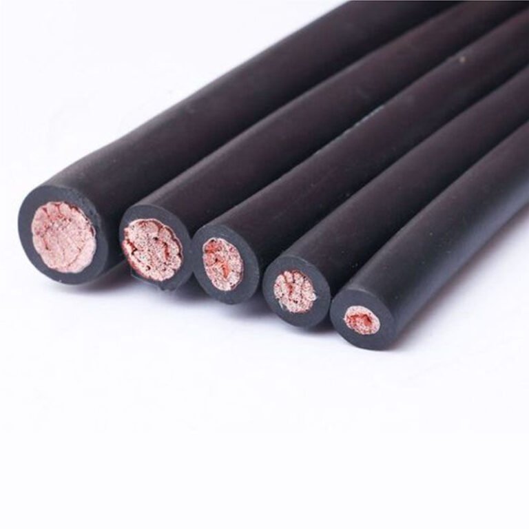
Solid conductor means fixed installation, full stop. Seven-wire stranding is standard for most building wire and power cable in fixed runs. Nineteen-wire stranded offers better flexibility and is common on medium-voltage cables. Class 5 fine stranded — sometimes called flexible stranding — is what you find on trailing cables, welding leads, and equipment connections that flex regularly. Rope-lay construction, where groups of strands are themselves twisted together, is used on highly flexible or very large cross-section conductors. If you’re looking at a cable with Class 5 stranding and an EPR jacket, that combination strongly suggests a flexible power application: a drag chain, a crane cable, something that moves.
Sketching the Cross-Section
Before reassembling your sample or discarding the cut piece, take two minutes to sketch the cross-section — number of cores, approximate core diameter, layer sequence, armor type, screen type. Photograph it. This becomes the permanent record for procurement and maintenance. Replacing a cable by conductor material alone without documenting the armor and screen layers has caused more than a few expensive mismatches when the replacement arrives on site.
Voltage Rating and Conductor Sizing: Matching Electrical Parameters to Application Requirements
The voltage rating is probably the single most abused piece of information on a cable — either ignored entirely during a rushed replacement job, or assumed from a cable’s physical size when it should be verified properly. Getting it wrong doesn’t just risk a failed inspection; it can result in insulation breakdown, arc flash, or a slow degradation fault that takes months to show up.
Understanding the Two-Number Voltage System
Every cable voltage designation carries two numbers, written in the format U₀/U — for example, 0.6/1kV or 6/10kV. U₀ is the rated voltage from any conductor to earth (or to the metallic screen), and U is the rated voltage between any two phase conductors. A 0.6/1kV cable is rated for 600V conductor-to-earth and 1000V conductor-to-conductor. That distinction matters in practice: in a solidly earthed system, the conductor-to-earth stress drives insulation thickness requirements, while conductor-to-conductor voltage governs inter-core insulation in multi-core designs.
The common industrial voltage classes run 300/300V, 300/500V, 0.6/1kV, 3.6/6kV, 6/10kV, 12/20kV, and 18/30kV. The jump from 0.6/1kV to 3.6/6kV is where confusion causes the most damage — these two classes can look nearly identical externally, especially in older stock with worn jacket printing.
Finding and Verifying the Voltage Rating
On most modern cables, the voltage class is printed directly on the jacket alongside the manufacturer name, standard reference, and conductor size — typically in a repeating sequence every 500–1000 mm. If the print is worn, legible sections are usually still findable under raking light or after cleaning with isopropyl alcohol.
When the print is truly gone, you need instrument verification. A Megger insulation resistance test (typically at 500V or 1000V DC depending on the cable class) will confirm whether the insulation is broadly intact, but it does not tell you the design rating — it only confirms present condition. A high-potential (hipot) test is more definitive: you apply a DC or AC overvoltage — usually 2U₀ + 1000V for low-voltage cables per IEC 60502 — and observe whether the insulation holds. This should only be done by qualified personnel on de-energised, isolated cables; on an installed run, you need to disconnect sensitive equipment at both ends first.
Wall thickness measurement is a faster field method for distinguishing voltage classes when markings are absent. A 0.6/1kV XLPE insulated core typically carries 0.7–0.9 mm of insulation wall thickness on a 4 mm² conductor. A 3.6/6kV cable on a similar conductor size runs 2.5–3.5 mm. Measure with a calibrated micrometer after careful stripping — not a knife estimate.
AWG vs. IEC Metric Sizing: A Practical Conversion
North American and international projects frequently collide on conductor sizing. The table below covers the range most commonly encountered in industrial and commercial work:
| AWG | Approximate mm² (IEC nearest standard) | Note |
|---|---|---|
| 4/0 (0000) | 120 mm² | AWG 4/0 = 107.2 mm² actual; 120 mm² is nearest IEC standard |
| 3/0 (000) | 95 mm² | AWG 3/0 = 85.0 mm² actual |
| 2/0 (00) | 70 mm² | AWG 2/0 = 67.4 mm² actual |
| 1/0 (0) | 50 mm² | AWG 1/0 = 53.5 mm² actual |
| 2 | 35 mm² | AWG 2 = 33.6 mm² actual |
| 4 | 25 mm² | AWG 4 = 21.2 mm² actual |
| 6 | 16 mm² | AWG 6 = 13.3 mm² actual |
| 8 | 10 mm² | AWG 8 = 8.37 mm² actual |
| 10 | 6 mm² | AWG 10 = 5.26 mm² actual |
| 12 | 4 mm² | AWG 12 = 3.31 mm² actual |
| 14 | 2.5 mm² | AWG 14 = 2.08 mm² actual |
The “nearest IEC standard” column is what gets used in practice, but they are not exact substitutes. A replacement cable sized to IEC 35 mm² pulled into a conduit designed for AWG 2 may be a tight fit; current-carrying capacity also differs slightly depending on whether the standard used is NEC 310 or IEC 60364. Don’t assume equivalence without checking both ampacity tables and conduit fill.
Measuring Conductor Size Without Markings
Strip back roughly 20–25 mm of insulation cleanly. For a solid conductor, measure the diameter directly with a micrometer and apply A = π(d/2)². For a stranded conductor, count the strands, measure one individual strand diameter, calculate the single-strand area, and multiply by strand count — then apply a compaction factor of roughly 0.93–0.97 for compressed-round stranding, lower (0.85–0.91) for older Milliken or sector-shaped conductors. This approach gets you within a few percent of the true cross-section, which is usually sufficient for replacement sizing decisions.
Multi-Core vs. Single-Core Parallel Runs
Above roughly 240–300 mm² (the exact threshold varies by installation method and available switchgear terminations), it becomes common practice to run two or three parallel single-core cables per phase rather than one large multi-core. This is normal in substations and large motor feeders. If you’re identifying an existing installation and find three sets of single-core cables on a common route, don’t assume they’re independent circuits — check the termination labels and measure phase relationship before drawing conclusions.
All Jinda cables carry voltage ratings tested and certified to IEC 60502 and GB/T 12706, with third-party test certificates available on request for each production batch.True
IEC 60502 and GB/T 12706 are the governing standards for extruded insulation power cables in the 1kV–30kV range. A manufacturer of Jinda's scale supplying 50+ countries routinely undergoes third-party certification to these standards; batch test certificates are standard practice in international cable procurement and verifiable through the certificate reference numbers provided.
Color Code Systems by Region and Standard: A Global Reference for Field Identification
Color is the fastest visual cue an electrician or inspector has when opening a panel or junction box. Grab a conductor, check the insulation color, and you have an immediate working hypothesis about its function. The problem — and this is worth stating plainly — is that hypothesis can be dead wrong if you don’t know which standard was applied during installation, or when.
Regional systems differ enough to kill someone who assumes the wrong one. Never identify a conductor function by color alone without confirming the applicable wiring standard first.
IEC 60446: The Dominant International Framework
Most of the world outside North America has converged on IEC 60446. Under this standard, the three line conductors (L1, L2, L3) are brown, black, and grey respectively; neutral is blue; and the protective earth is the unmistakable green-yellow bicolor. This covers the European Union, most of Asia (including new installations in India, Southeast Asia, and the Gulf states), much of Africa, and the majority of South American industrial installations. If you’re commissioning a new greenfield plant in Poland, Vietnam, or Kenya, this is what you’ll find — assuming the contractor followed code.
The green-yellow earth wire is essentially universal in IEC territory. It’s one of the few identifiers that transferred cleanly across regional variants.
NEC / NFPA 70: North American Conventions
The United States and Canada operate under a different logic, partly because NEC doesn’t mandate specific phase colors — it mandates that colors be consistent within an installation, with a few hard rules around neutral and ground. In practice, the industry default for 120/208V three-phase systems is black, red, and blue for the phases; white or grey for neutral; green or bare copper for equipment ground. Step up to 277/480V distribution and the convention shifts to brown, orange, and yellow for phases — which means brown, used as a phase conductor in a 480V US panel, carries a completely different meaning than brown in an IEC installation where it’s L1. That overlap causes real confusion on international projects.
NEC mandates specific phase conductor colors for three-phase systemsFalse
NEC / NFPA 70 does not mandate specific phase colors; it requires consistency within an installation. The black-red-blue and brown-orange-yellow conventions are industry practice, not code requirement, though some jurisdictions have adopted them by local amendment.
AS/NZS 3000 and the Australian Mixed-Era Problem
Australia and New Zealand present a particularly messy maintenance environment. The post-2000 AS/NZS 3000 revision harmonized with IEC, replacing the old red phase with brown and black neutral with light blue. Anyone maintaining a building wired before roughly 2001 will find red where they’d now expect brown — same conductor function, completely different color. In a refurbishment project where new circuits feed into existing infrastructure, you can have both conventions in the same cabinet. Always verify installation date and check switchboard documentation before touching anything.
BS 7671 and UK Legacy Wiring
The UK harmonized with IEC in 2004 via Amendment 2 to BS 7671, adopting the brown/black/grey phase and blue neutral scheme. But pre-2004 British wiring used red for phase, yellow and blue for the other phases in three-phase, and black for neutral — a scheme that conflicts with IEC on nearly every conductor. Red in a pre-2004 UK installation is a live phase conductor. Red in a post-2004 installation should no longer appear, but renovation work constantly surfaces old wiring. The Health and Safety Executive guidance recommends sleeving old conductors with the new-standard colors when extending or modifying circuits, but in practice that doesn’t always happen.
Chinese GB/T 6995 and Jinda’s Export Customization
China’s national standard GB/T 6995 assigns yellow, green, and red to the U, V, and W phase conductors; light blue to neutral (N); and the standard green-yellow bicolor to the protective earth (PE). For domestic supply this is straightforward. The complication arises on export orders — a cable manufactured to GB/T 6995 for a Chinese plant cannot simply be shipped to a German facility and assumed to be correctly coded under IEC 60446. Yellow in GB/T territory is a phase conductor; in an IEC panel, yellow-green is earth-only. Jinda handles this at the order level: customers specifying international projects should call out the target wiring standard, and cables get manufactured with the correct insulation colors from the extrusion stage. Retrofitting colors after the fact is not a reliable solution.
Special-Application Color Systems
Instrumentation cables — the multi-pair twisted cables common in process plants — use their own pair-numbering convention, often cycling through a set of solid/striped color pairs with an individual drain wire per pair. Don’t confuse these with power conductors; the insulation is typically thinner and the color logic follows ISA or manufacturer conventions rather than any power wiring standard.
Thermocouple extension cables have their own entirely separate color system defined by IEC 60584-3, where the overall cable color and conductor colors both encode the thermocouple type (Type K, J, T, etc.). Connecting thermocouple extension cable by power-wiring color conventions is a calibration disaster waiting to happen.
Fire-resistant cables in many national codes — including Chinese GB, British BS, and various Middle Eastern standards — use a red outer jacket as a functional identifier for the cable type, not the conductor function inside.
Field Protocol: Unknown Junction Box with Mixed-Era Wiring
You open a junction box in an older industrial building. No labels. Multiple cable entries, clearly from different installation eras judging by jacket condition and print-line formatting. This is a real scenario, and the correct sequence is:
First, de-energize and verify zero-voltage with a calibrated tester on every conductor before touching anything. Color tells you nothing reliable yet. Check any available drawings, panel schedules, or as-built documentation to establish what wiring standard was in use at each installation date. If the building has had multiple fit-outs, you may be looking at two or three different standards simultaneously.
Once you have a working hypothesis for each cable’s standard, use the color to suggest function, then verify electrically. Neutral and earth conductors in a live system should read near zero voltage to earth — but a miswired or faulted installation can violate that. Only after electrical verification should you confirm conductor identity and proceed with any connection work.
Color is the starting point. It should never be the ending point.
Cable Type Identification by Application Category: Power, Control, Instrumentation, Data, and Specialty
When jacket markings are worn, cut off, or simply never applied — which happens more often than anyone admits on older installations — the cable’s own physical character becomes your primary identification tool. Application context narrows the field fast. A cable pulled from a motor control center and a cable pulled from a rack in a data room are going to be fundamentally different animals even before you measure anything.
Power Cables
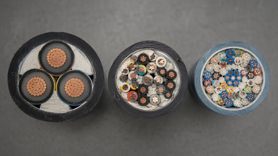
Large cross-section is the first tell. Low-voltage power cables typically run from 10 mm² up through 300 mm² or larger, and medium-voltage designs add a notably thick insulation wall — usually 3–6 mm for the 6–35 kV range, depending on voltage class and standard. Conductors may be circular (fine stranded or solid) or sector-shaped; sector conductors appear in multi-core designs to reduce overall cable diameter and are almost exclusively a power cable feature. Look for designations like YJV, NYY, or XLPE SWA stamped on surviving jacket sections. Steel wire armor or steel tape armor, combined with a thick outer PE or PVC oversheath, strongly suggests a power feeder application. Medium-voltage cables also typically carry a semi-conductive screen over both conductor and insulation — a thin black layer that’s unmistakable once you’ve seen a cross-section.
Control Cables
Control cables often get misidentified as small power cables in the field. The distinguishing feature is core count relative to conductor size. You’ll commonly find 4, 7, 12, 19, or even 37–61 cores, each typically 0.75–2.5 mm², sometimes up to 6 mm² for heavier switching duties. Individual cores are thin-walled, color-coded sequentially, and the overall cable diameter stays compact relative to the number of conductors. Some designs include an overall screen (copper braid or foil plus drain wire) for noise immunity in PLC environments, but individual pair screening is rare — that’s instrumentation territory.
Instrumentation Cables
The twisted pair or triad construction is the giveaway. Each signal pair is twisted at a defined lay length and wrapped in its own foil screen with a drain wire — this is individual shielding (IS). An outer overall shield (OS) wraps everything. Low-capacitance insulation materials like HDPE or foam polyethylene keep signal integrity intact across long 4–20 mA loop runs. If you unroll a cross-section and see layered foil shields, multiple drain wires, and tight twist pitches varying between pairs, you’re holding instrumentation cable. Thermocouple extension cables add a specific wrinkle: conductor alloys vary by thermocouple type (Type K uses chromel/alumel, visually distinct from copper), and mis-substituting standard copper control cable in a thermocouple circuit introduces measurable temperature error.
Data and Network Cables
Cat5e, Cat6, and Cat6A are distinguished partly by jacket stiffness and pair twist rate variation — Cat6 and Cat6A incorporate a central spline separator, which you can feel immediately when you flex the cable. Cat6A is noticeably bulkier. Coaxial cable carries an impedance marking directly on the jacket: 50 Ω for RF and industrial Ethernet (RG-58, RG-213 types), 75 Ω for broadcast video and CATV. Don’t guess — using 75 Ω cable on a 50 Ω RF system introduces a standing wave ratio that degrades signal measurably. Fiber optic jacket color follows a widely adopted convention: yellow for OS2 singlemode, orange for OM2 multimode, aqua for OM3/OM4 — though non-compliant manufacturers occasionally deviate, so always verify with an OTDR if the application is critical.
Flexible and Trailing Cables
Extreme flexibility is structural, not incidental. Class 5 and Class 6 stranding means dozens or hundreds of fine copper wires per conductor, giving the cable a distinctly soft, almost rope-like feel compared to a rigid power cable of the same cross-section. Rubber or TPE jackets resist repeated bending cycles without cracking — a standard PVC jacket would fail quickly in a drag chain application. If you’re looking at a cable from a crane bridge, a welding set, or a moving machine axis and it has this characteristic limpness and a tough, slightly textured jacket, that’s your identification.
Fire-Resistant and Fire-Alarm Cables
Cut the cable end and look carefully at the insulation layer. A white or cream mica tape wrapped tightly beneath the insulation is the defining structural feature of a fire-resistant cable — it maintains electrical circuit integrity after the polymer insulation has already burned away. IEC 60331 compliance and a circuit integrity time rating (PH30, PH60, PH120) should appear in the jacket print, with PH120 indicating 120 minutes of fire survival under the test standard. Red jacket convention is widely used for fire-alarm wiring, though it’s a convention rather than a universal regulation, so don’t rely on color alone without confirming the mica tape layer.
Mica tape beneath insulation is the structural basis for IEC 60331 fire-resistant cable circuit integrity, not the outer jacket material or color.True
IEC 60331 tests electrical circuit continuity under direct flame exposure. The mica tape layer maintains insulation function after the polymer burns; outer jacket color is a convention only and provides no fire performance.
Submarine and Direct-Burial Cables
Weight is the first clue — these cables are heavy relative to their conductor size. The layered construction typically runs: inner conductor, insulation, inner PE or lead sheath (lead is now less common but still encountered in older installations), steel wire armor in one or two layers, and a bitumen-impregnated or polypropylene yarn outer serving. The bitumen coating often gives a faint tar smell on older cables. Direct-burial cables used in terrestrial runs may omit the lead sheath but retain heavy galvanized steel wire armor and a thick PE oversheath. Don’t confuse standard armored LV cable with a true submarine design — the armor wire gauge and overall wall thicknesses are substantially heavier in submarine-rated product.
Photovoltaic Solar Cables
These are appearing on industrial sites at a rate that catches procurement teams off guard. A UV-stabilized black jacket — almost always cross-linked polymer, not standard PVC — combined with tinned copper conductors (which resist the sulfur-compound degradation that bare copper suffers outdoors) and a 1500V DC voltage rating stamped on the jacket are the key identifiers. Look for TÜV 2 Pfg 1169 or UL 4703 in the print line. Using standard low-voltage AC cable rated at 450/750V in a 1500V DC PV string is a genuine safety hazard; DC fault current behavior is fundamentally different from AC, and the insulation voltage class mismatch creates a long-term dielectric stress that won’t show up immediately but will degrade the installation over years.
Field Testing Methods to Confirm Cable Identity When Visual Inspection Is Not Enough
Print lines fade. Jackets get painted over, cut short, or simply never got marked properly at the factory. When you’re standing on a live plant floor holding a reel of unmarked cable or trying to verify what’s already pulled through conduit, you need measurable evidence — not guesswork.
Insulation Resistance Testing with a Megohmmeter
The IR test is usually the first instrument check on any suspect cable. Apply DC voltage between conductor and screen (or conductor and earth for unscreened cable) using a calibrated megohmmeter — a Megger MIT430 or equivalent works fine for most medium-voltage checks — and hold for 60 seconds. IEC 60502 sets minimum IR values that scale with voltage class: for 0.6/1 kV cable at 20°C, expect at least 100 MΩ·km on new cable, though field-aged cable in good condition typically reads 500 MΩ·km to several GΩ·km. IEEE 400 guidance for HV cables is more involved and uses a PI (polarization index) ratio — the 10-minute reading divided by the 1-minute reading — where values below 1.0 suggest serious moisture ingress or degraded insulation.
Low IR doesn’t just mean the cable is old. Wet terminations, XLPE that’s been tree-tracked, or a PVC jacket that’s become brittle and cracked all show up here. A very low reading on a cable claimed to be XLPE-insulated but actually PVC is a legitimate red flag — PVC degrades faster under sustained high-voltage polarization, and the IR curve shape differs from XLPE’s characteristic steep rise.
Conductor Resistance and Material Verification
A four-wire Kelvin measurement — micro-ohmmeter with separate current and voltage leads — eliminates contact resistance and gives you actual DC resistance per meter or per kilometer. Cross that against IEC 60228 Class 1 and Class 2 tables: copper at 20°C runs roughly 17.2 µΩ·mm at 1 m (or 18.1 mΩ/m for 1 mm² conductor), while aluminum is about 60% more resistive per unit cross-section. If your measurement comes back 40–45% higher than the copper table value for a nominally copper conductor, you’re probably looking at copper-clad aluminum (CCA). That’s important — especially in procurement verification where CCA sometimes gets passed off as solid copper.
Tone Generator Tracing for Multi-Core Cables
For identifying individual cores in a pulled multi-conductor cable without energizing it, connect a tone generator to one conductor at one end and use an inductive probe to sweep the conductors at the other. The target core produces a clearly different pitch or volume from adjacent unconnected cores. Work one core at a time, mark it, then move to the next. In practice, keep the generator signal below 1 V and confirm the circuit is fully isolated before starting — capacitive coupling in shielded instrumentation cable can produce misleading signals on adjacent cores if your probe sensitivity is set too high.
Capacitance as a Cable-Type Discriminator
Instrumentation cables are deliberately manufactured for low capacitance — typically under 100 pF/m for individually shielded pairs — because high capacitance corrupts 4–20 mA and HART signals over long runs. Power cables don’t have that constraint and usually measure several hundred pF/m depending on insulation thickness and conductor spacing. A quick capacitance measurement with an LCR meter can confirm whether an unidentified cable is instrument-grade or power-grade when construction alone is ambiguous.
Flame and Smoke Identification (Workshop, Not Field)
Cut a 150 mm sample, clamp it, apply a small flame for 15 seconds, then withdraw. PVC ignites readily, burns with thick black smoke, and usually continues burning after the flame is removed. LSZH self-extinguishes within a few seconds and produces noticeably less smoke — white or light grey. Silicone insulation chars and forms a white ash residue but doesn’t drip flaming material. Never do this on a live installation or in a confined space.
LSZH cable self-extinguishes and produces significantly less smoke than PVC when tested per IEC 60332-1True
IEC 60332-1 and IEC 61034-2 test protocols confirm LSZH compounds are formulated to limit flame propagation and smoke density, which is the core reason they are specified in tunnels, data centers, and public buildings.
XRF Analysis for Conductor Authentication
Handheld X-ray fluorescence analyzers — units from brands like Olympus Vanta or Bruker are common in cable authentication labs — can confirm elemental composition in under 30 seconds on an exposed conductor cross-section. For bulk procurement verification, this is increasingly the standard way to catch CCA substitution. The analyzer reports copper and aluminum percentages directly. On a legitimate Class 2 stranded copper conductor, aluminum content should read near zero. A reading of 15–40% aluminum in a supposedly all-copper cable is a procurement problem, not just an electrical problem.
Building the Cable Identification Record
All of this testing is only as useful as the documentation tied to it. A practical site record sheet should capture: cable sample location or reel number, jacket marking transcription (or photograph), IR test voltage and result with temperature correction, DC resistance measurement and IEC 60228 comparison, capacitance reading, any flame test observations, XRF data if conducted, and the technician’s conclusion on cable type and condition. Photographs of the cable end, the test setup, and any physical construction clues round out the record. That package becomes part of project handover documentation — and when a fault occurs two years later, that traceability is worth far more than the hour it took to create it.
Common Cable Identification Mistakes and How to Avoid Them in Industrial Projects
Experienced engineers still get burned by these errors. Some are embarrassing. A few have caused fires, failed inspections, or triggered full rewiring jobs on plants that had just been commissioned. Here are the ones worth knowing cold.
Assuming Color Coding Is Universal
Brown means line conductor in an IEC 60446 installation. In a UK installation wired before the 2004 harmonization, brown was the neutral. Same color, opposite function. If you’re walking into a facility that was built or extended across multiple decades, you cannot assume the color convention is consistent even within the same panel.
Always check two things: which standard governs the installation, and what year the specific circuit was installed. AS/NZS 3000 adds another layer — red for active, which clashes with NEC expectations for anyone used to working US sites. In practice, a quick look at the installation date stamped on the panel schedule, cross-referenced with the local wiring standard in force at that time, takes maybe two minutes and has saved more than a few people from a very bad day.
Confusing CCA with Solid Copper
Copper-clad aluminum looks identical to copper in cross-section until you scrape the conductor with a knife blade or a coin. The aluminum core shows silver-grey underneath the thin copper layer. This matters enormously for ampacity — CCA carries roughly 60–70% of the current of equivalent copper, depending on strand count and cladding thickness, so a CCA 2.5 mm² cable should never be substituted into a circuit rated and protected for copper 2.5 mm².
The scrape test takes ten seconds. A four-wire resistance measurement on a known length gives you a resistivity figure you can compare against IEC 60228 values for copper and aluminum. Do both checks before accepting a critical supply replacement from any unfamiliar source, regardless of what the label says.
Misreading the Voltage Rating
Using a 0.6/1 kV cable on a 6/10 kV circuit will result in catastrophic insulation failure.True
IEC 60502-1 covers cables rated up to 1 kV; IEC 60502-2 covers 6/10 kV and above, with significantly greater insulation wall thickness requirements. A 0.6/1 kV cable lacks the dielectric strength to survive sustained operation at medium voltage.
Insulation wall thickness in IEC 60502-2 cables is substantially greater — we’re talking roughly 3.4 mm versus under 1 mm for the same conductor cross-section, depending on voltage class and conductor size. Verify wall thickness with a calibrated micrometer on a cut sample, and check it against the published tables. Visual inspection of the outer jacket alone tells you almost nothing about the voltage class.
Ignoring the Temperature Rating Suffix
THHN is rated 90°C in dry locations. THWN is 75°C in wet locations. Both are commonly stocked, often in the same reel storage area, and both can share a black jacket. When a conduit run fills with condensation — which happens seasonally in outdoor riser conduits in humid climates — the wet location rating applies, and THHN’s 90°C dry rating provides no protection. The derating math changes, the protective device coordination changes. This one tends to show up as a nuisance trip in summer before it shows up as a failure.
Treating All Black-Jacketed Cables as the Same
Black jacket appears on power cables, multicore instrumentation cables, solar PV DC cables (which have specific UV resistance and double insulation requirements), and heavy-duty rubber trailing cables for mobile equipment. A trailing cable rated for repeated flexing in a mining environment has an entirely different construction to a fixed-installation armored power cable, even if both are black, roughly the same diameter, and sitting next to each other in a cable store. Jacket color is a starting point, never a conclusion.
Relying on Country-of-Origin Assumptions
The assumption that cables manufactured outside Europe or North America don’t meet IEC or UL standards is outdated and operationally dangerous — but so is the opposite assumption that any printed standard marking is genuine without verification. The print line is the right place to look. A cable manufactured in China that carries a legitimate IEC 60502-2 or UL 44 marking, backed by a third-party test certificate from TÜV, SGS, or Bureau Veritas, is what the marking says it is. A cable with a hand-applied sticker is not.
Cable certifications from accredited third-party bodies such as TÜV and SGS provide independent verification that a cable meets the stated standard, regardless of manufacturing country.True
Accredited certification bodies conduct factory audits and independent sample testing against the referenced standard. The certification mark on the print line, cross-referenced with the issuing body's certificate database, is the reliable confirmation of compliance.
Procurement Best Practice Before Any Bulk Order
Request three things from every supplier before committing to volume: a cable test certificate (CTC) from a recognized third-party body, a factory acceptance test (FAT) report for the specific production run, and a physical sample spool with a legible, complete print line. Compare the print line against the test certificate — manufacturer name, standard reference, voltage rating, and conductor class should all match. If the supplier can’t produce all three within a reasonable lead time, that tells you something useful before you’ve committed a budget.
How to Build a Cable Identification and Documentation System for Long-Term Asset Management
A cable you can identify on day one of commissioning is useful. A cable you can still identify accurately in year 23, after three ownership changes, two control system upgrades, and a flood that wiped out the original paper records — that’s where documentation systems earn their keep.
Facilities running 20 to 40 years routinely face the same problem: a fault occurs on a circuit, and nobody can confirm what cable is actually installed without pulling it out or guessing from a faded, half-legible drawing. That scenario costs real money — unplanned downtime typically runs $5,000 to $50,000 per hour depending on the process, and the range is that wide because it genuinely depends on what the circuit feeds.
Why the Documentation Investment Pays Back
Accurate cable records compress fault response time considerably. A maintenance tech who can pull up a cable schedule on a tablet and confirm conductor size, insulation class, and route in under two minutes makes very different decisions than one working from memory or a 1998 as-built drawing that may or may not reflect three subsequent modifications. Compliance audits — whether for IEC 61439, local electrical authority inspections, or insurance underwriters — increasingly require traceability back to original factory test certificates. Gaps in that chain can delay facility certification or affect liability coverage after an incident. That last point is underappreciated until it isn’t.
What a Cable Schedule Actually Needs to Contain
A workable cable schedule isn’t a spreadsheet with five columns. At minimum, each record should carry: a unique tag number tied to the plant’s equipment numbering logic; a route description that references physical landmarks (cable tray number, duct bank grid reference, panel designation at each end); full cable type and designation exactly as printed on the jacket; manufacturer name and batch or reel number; conductor count and cross-sectional area (both AWG and mm² if the project spans regional standards); voltage rating; installed length in meters; installation date; and a reference to the factory test certificate and any post-installation test record (insulation resistance, hi-pot result, continuity). That last column is the one most schedules omit, and it’s the first one an insurance adjuster asks for.
Drum and Reel Labeling Before the Cable Leaves the Yard
Every drum that arrives on site should carry a durable identification tag — either a stamped metal plate or a heat-shrink sleeve rated for outdoor exposure — attached to both ends of the drum before installation begins. It should replicate the jacket print line data plus the installer’s company name and the project tag number assigned to that reel. In practice, this step gets skipped under schedule pressure. The cost of skipping it shows up years later when a partial reel in a cable store has no traceable origin and procurement has to re-test or replace it entirely.
Digital Tools and QR Code Tagging
Plant information management systems (PIMS), GIS-based cable routing databases, and BIM models for greenfield projects all provide a home for cable schedule data that survives personnel turnover. The growing practice of applying QR code or barcode labels to cable ends at every termination point — now common in data centers and increasingly adopted in process plant MCC rooms — lets a technician scan a cable lug with a smartphone and pull up the full digital record instantly. Setup takes effort. In service, it’s faster than any paper-based alternative.
Periodic Re-Inspection Intervals
Visual jacket inspection and insulation resistance testing every 3 to 5 years is a reasonable baseline for MV cables. Any circuit that has shown abnormal load history, a tripped protective device without a clear cause, or physical disturbance (excavation near a duct bank, for instance) should go to the front of the queue regardless of schedule.
Jinda issues factory test certificates per IEC or client-specified standards for every project supply batch, with full reel-level traceability retained for post-project identification and replacement sourcing.True
This is standard practice at manufacturers operating under ISO 9001-certified quality systems serving EPC and utility clients who require certificate traceability; Jinda's integrated R&D, production, and after-sales structure supports this across its five production bases.
For long-term procurement support, Jinda’s technical team can cross-reference original batch data against a replacement inquiry years after initial supply — useful when a partial cable failure on a 15-year-old installation requires a like-for-like replacement that matches the original construction exactly, not just the nominal designation.
Frequently Asked Questions About Cable Type Identification
How do I tell if a cable is copper or aluminum without cutting it?
The simplest non-destructive method is a weight check. Copper runs roughly 8.9 g/cm³ against aluminum’s 2.7 g/cm³ — so for the same cross-sectional area, a copper conductor is approximately 3.3 times heavier. Cut or measure a known length of cable, strip back a short section to expose the conductor, then compare the weight of that length against published kg/km tables for both materials at the suspected cross-section. A 10 m sample is usually enough to give a clear result with a decent postal scale.
If you can access the conductor ends, a four-wire resistance measurement (Kelvin method) is cleaner. Aluminum has roughly 61% of copper’s conductivity at the same cross-section, so the resistance per kilometer will be noticeably higher. On-site, a good low-resistance ohmmeter — a Megger DLRO or equivalent — will give you a number you can cross-check against IEC 60228 table values. Color alone is unreliable; aluminum conductors are sometimes tin-plated and look silver-grey, but so are some tinned copper conductors.
What does ‘XLPE’ mean on a cable label, and why does it matter?
XLPE stands for cross-linked polyethylene. The cross-linking process converts a thermoplastic material into a thermoset — meaning it won’t soften and flow under sustained heat the way standard PVC does. The practical consequence: XLPE-insulated cables are rated for 90°C continuous conductor temperature versus 70°C for ordinary PVC, which translates directly into higher current-carrying capacity for the same conductor size, or longer service life at the same load. Moisture resistance is substantially better too, which matters in buried or wet-location installations.
XLPE appears on cables from 0.6/1 kV distribution cables all the way up through 33 kV and beyond. If you’re replacing a cable in a high-ambient-temperature environment — a furnace room, a rooftop conduit run in a hot climate — swapping XLPE for standard PVC is a performance downgrade even if the conductor size is identical.
XLPE insulation maintains its rated dielectric properties at 90°C continuous conductor temperature, compared to 70°C for standard PVC, per IEC 60502-1.True
This distinction is defined in IEC 60502-1 and is consistent with conductor temperature ratings specified in IEC 60228 and cable current-rating standards such as IEC 60364-5-52.
Can I use a cable rated 0.6/1 kV on a 480 V three-phase system?
Yes. The 0.6/1 kV designation means 600 V phase-to-earth and 1000 V phase-to-phase. A 480 V three-phase system sits at 277 V phase-to-earth — comfortably inside both limits. That said, always verify the specific installation code in your jurisdiction. NEC installations in the United States, for example, have additional conduit fill, ampacity correction, and listing requirements that go beyond voltage class alone.
How do I identify the neutral conductor when color markings aren’t visible?
First, a continuity test maps all conductors end to end so you can account for every core. Once you know which conductors go where, a calibrated phase sequence indicator or a contact voltage tester (with proper authorization and live-work permit in place) confirms which conductors are phase and which is neutral on an energized circuit.
One thing worth flagging separately: in instrumentation and control cables, the drain wire — that bare or lightly insulated wire running alongside the foil shield — is always the shield ground return. It is not a signal conductor and not a neutral. Confusing the drain wire with a spare signal conductor is a wiring error that turns up more often than it should.
What is the difference between a screened cable and an armored cable?
These are two different layers solving two different problems, and a cable can have both simultaneously.
Screening — a foil wrap or braided layer sitting inside the outer jacket, around the insulated conductors — exists purely for EMI/RFI shielding. It protects signal integrity. Armor — steel wire armor (SWA), steel tape armor (STA), or aluminum wire armor (AWA) — sits over the outer sheath and provides mechanical protection against crushing, rodents, and dig-in damage. To tell which you have, cut a clean cross-section sample with a cable knife and examine the layer order. If the metallic layer is inside the outer jacket but outside the insulation, it’s a screen. If it’s outside the outer sheath — or is the outermost layer under a thin oversheath — it’s armor.
How do I verify a cable from a Chinese manufacturer meets IEC or UL standards?
Start with the print line. A compliant cable will carry the specific standard designation — IEC 60502-1, UL 44, UL 83, or whichever applies — not a vague “meets international standards” claim. From there, request the third-party test certificate issued by an accredited body: TÜV Rheinland, SGS, Bureau Veritas, and Intertek all maintain publicly searchable certificate databases. Pull the certificate number and verify it directly on the certifying body’s website. If the number doesn’t resolve, treat that as a red flag regardless of what the paperwork says.
Jinda’s cables carry traceable third-party certification; certificate numbers are available on request and can be verified independently.
What is the safest way to identify an unknown installed cable that may be energized?
Assume it’s live until you’ve proven otherwise with instruments, not by looking at it. Use a non-contact voltage tester first — an NCV pen gives a fast initial indication. Follow that with a calibrated multimeter measuring phase-to-earth and phase-to-phase voltage, which confirms both presence and magnitude. Apply full lockout/tagout per your facility’s electrical safety procedure before any physical identification work begins. This is not a step to streamline under schedule pressure; an energized cable at 480 V or above leaves no margin for a procedural shortcut.
Does Jinda provide custom cable identification markings for project-specific orders?
Yes. Custom print lines, drum labels, project-specific color coding, sequential meter marking, and tailored test documentation are all available for OEM, EPC, and bulk procurement customers. For large or technically specific projects, the Jinda technical sales team can work from your specification package to produce cable that arrives on-site already identified to your asset management system. Contact Jinda with your project specifications for a detailed quotation.