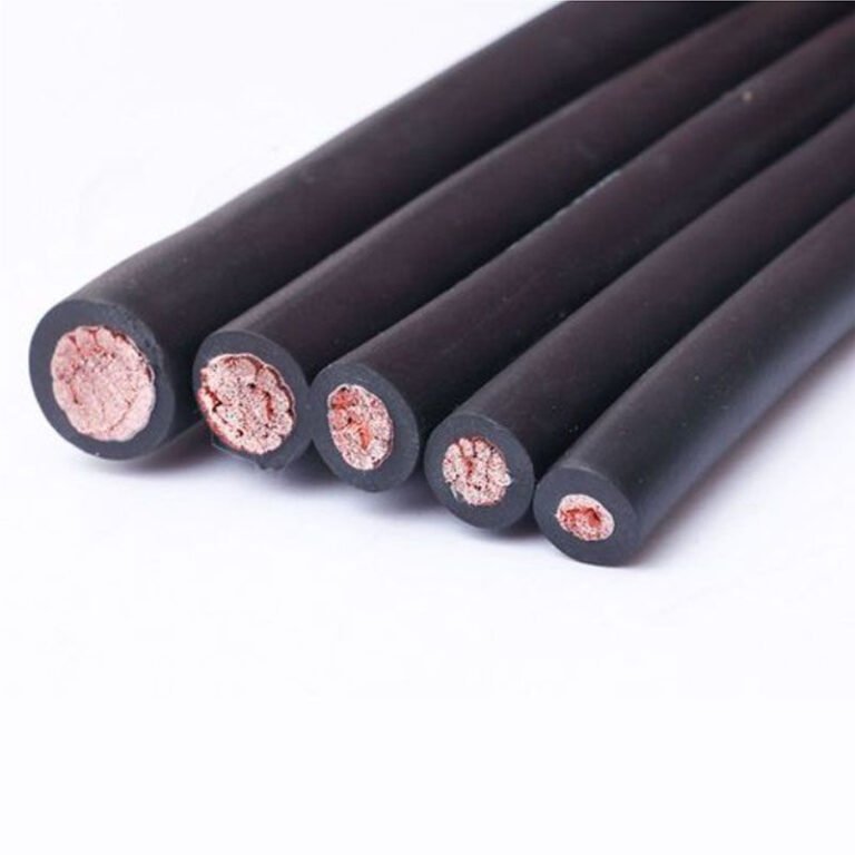
Wrong cable selection shuts lines down. Not slowly, not theoretically — a misspecified cable degrades insulation within months in the wrong environment, trips protective devices at the worst possible moment, and turns a sub-$500 procurement decision into a $50,000–$200,000 unplanned outage depending on your industry and line throughput. The problem isn’t that engineers don’t care; it’s that “industrial cable” covers an enormous, genuinely confusing range of products, and the wrong shortcut early in a project compounds itself all the way to commissioning.
Industrial cables fall into several major categories: power cables, control cables, instrumentation cables, data and communication cables, flexible and drag-chain cables, specialty cables (fire-resistant, halogen-free, mining-grade, subsea), and medium-to-high voltage cables. Each type is engineered around a specific combination of voltage class, mechanical stress, environmental exposure, and signal integrity requirement. Choosing the right type — and the right construction within that type — determines installation longevity, system reliability, and total lifecycle cost.
The global industrial cable market sat around USD 225 billion in 2023 and is tracking toward roughly USD 310 billion by 2030, which tells you something useful: this is not a commodity sector coasting on legacy demand. Electrification, automation, and the shift toward harsher deployment environments — offshore platforms, automated warehouses, high-cycle robotics cells — are pulling cable engineering in several directions at once. Understanding what each cable type actually does, where it fails when misapplied, and what to look for in a specification is worth more than any market forecast.
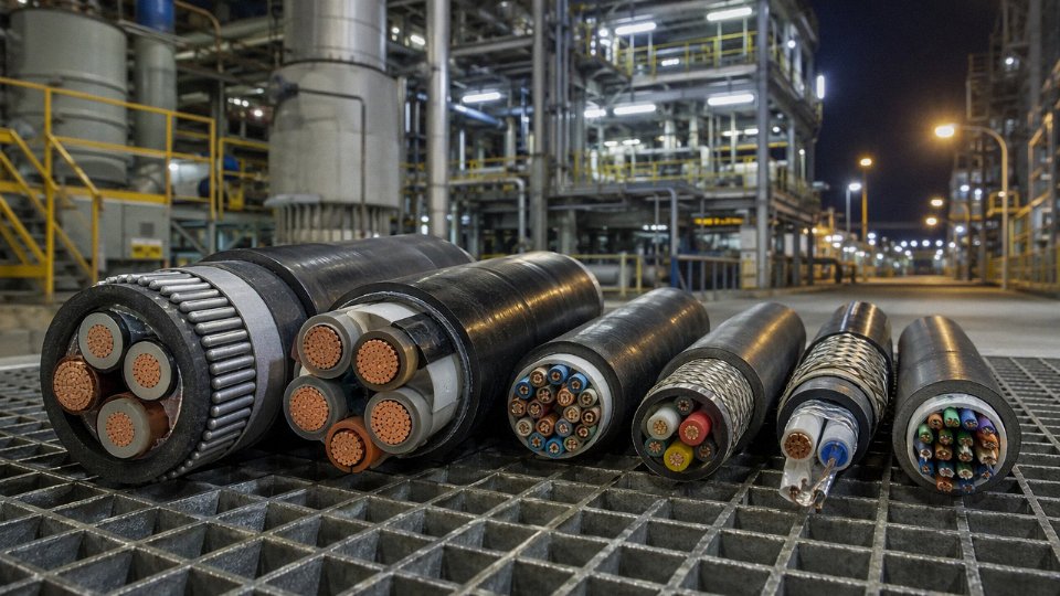
Power Cables Versus Control Cables Versus Instrumentation Cables: Core Functional Differences
These three cable families sit at the core of almost every industrial installation, yet they get confused — and substituted for one another — more often than most engineers would like to admit. Getting the distinction wrong costs money at best. At worst, it causes process upsets, corrupted measurement data, or a protection relay that won’t trip when it should.
Power Cables: Moving Energy at Scale
Power cables do one job: carry load current from a source to a load — motor, transformer, switchgear, distribution board, whatever sits at the end of the run. That job demands large conductors, typically 6 mm² on the low end up to 2,500 mm² for main feeder cables in heavy industry, though most plant-floor runs fall somewhere between 16 mm² and 300 mm² depending on load, distance, and derating factors like ambient temperature and grouping. Insulation is usually XLPE or EPR, both chosen for thermal resilience — XLPE handles continuous operating temperatures to 90 °C, EPR tends to stay flexible at low temperatures and handles higher short-circuit peaks, which matters in offshore and petrochemical environments. Armoring (steel wire armor or aluminum wire armor) is standard for buried routes or any installation with genuine mechanical exposure.
Voltage ratings run from 0.6/1 kV for general LV distribution up through 6/10 kV, 20/35 kV, and into 66/132 kV for transmission-class cables. The conductor cross-section and insulation wall thickness scale together with voltage class, so you can’t mix these up without obvious physical evidence.
Control Cables: Signal Routing for Discrete Commands
Control cables carry the switching and relay signals that tell field devices what to do — open that valve, energize that contactor, confirm that limit switch has tripped. The currents involved are low, the voltages modest (typically rated 450/750 V or 0.6/1 kV), and the conductors are small, ranging from 0.75 mm² up to about 6 mm². Multi-core construction is standard: a single control cable might contain anywhere from 4 to 61 cores, color-coded and numbered, running between a control panel and a marshalling cabinet or directly to field devices.
Many control cables include an overall screen — a copper braid or foil — to cut down on electromagnetic interference from nearby power runs. In practice, unscreened control cable pulled through the same tray as variable-frequency drives is asking for spurious trips. That’s a lesson learned the hard way on more than a few commissioning jobs.
Instrumentation Cables: Precision Signal Integrity
Instrumentation cables operate at a different level of criticality. They carry low-level analog signals — 4–20 mA current loops, millivolt outputs from thermocouples, resistance signals from RTDs, HART communication superimposed on a 4–20 mA loop — where even modest crosstalk or capacitance variation distorts the measurement. A 1% error in a flow measurement might be acceptable in a utility application; in a custody transfer or reactor temperature loop, it isn’t.
The construction reflects this: individual pair or triad shielding (each pair has its own foil screen with a drain wire) plus an overall shield around the entire cable. Capacitance tolerances are tight, typically specified at less than 100 pF/m, sometimes tighter for long runs. Resistance matching between pairs matters for thermocouple extension cables specifically. These cables are available as single pair, and multipair designs run up to 20 pairs or more in a single outer jacket.
The Substitution Mistake That Keeps Appearing
The most common project error is using standard control cable in place of instrumentation cable to save cost or because the right stock wasn’t available. The result in a DCS-based process plant is predictable: 4–20 mA loops start picking up noise from adjacent cores, signals drift by a few tenths of a milliamp, and the DCS starts logging spurious alarms or, worse, logging nothing because the noise is slow enough to look like process drift. Diagnosing that after the cable is already pulled through conduit is expensive and slow.
Substituting unshielded control cable for individually-screened instrumentation cable in a 4–20 mA loop application is a documented cause of measurement noise and DCS signal integrity problems in process plants.True
Individual pair shielding in instrumentation cable suppresses capacitive crosstalk between adjacent signal pairs. Without it, low-level analog signals share interference from neighboring cores, degrading loop accuracy in proportion to cable length, signal amplitude, and proximity to noise sources.
Quick Selection Reference
| Application Condition | Correct Cable Family |
|---|---|
| Load current above 16 A | Power cable |
| Discrete on/off switching signals, relay logic | Control cable |
| Signal amplitude below 5 V, or 4–20 mA loop precision required | Instrumentation cable |
| Thermocouple or RTD signal | Instrumentation cable (matched extension type) |
| Actuator power + position feedback on same route | Consider hybrid construction |
Hybrid Cables for Complex Installations
Offshore platforms and mobile machines — cable reels on cranes, flexible connections on automated guided vehicles — often can’t afford the conduit space or weight for three separate cable runs. Jinda’s integrated R&D and production setup allows engineering of hybrid cables that combine power cores and individually-screened instrumentation pairs within a single outer sheath, with physical separation maintained inside the cable to limit interference between the power and signal sections. This isn’t a standard catalog item most suppliers offer; it requires coordinated design of the conductor geometry, shielding arrangement, and jacket material from the outset, which is why having R&D and production under the same roof matters for these projects.
Voltage Class Breakdown: Low, Medium, High, and Extra-High Voltage Industrial Cables
Voltage class is the single most consequential variable in cable construction. Get it wrong in one direction and you’re over-specified and paying for insulation wall thickness you don’t need; get it wrong in the other direction and you’re looking at dielectric breakdown, arc flash, or a fire inside conduit. Every other selection parameter — insulation material, shielding geometry, sheath design, drum length — cascades from voltage class first.
Low Voltage (LV): Up to 1 kV
Most of what engineers handle day-to-day falls here. LV cables use PVC or XLPE insulation over stranded copper or, in larger cross-sections, aluminum conductors. Construction is relatively straightforward: insulated cores twisted together, a bedding layer, an optional armour (SWA or AWA for mechanical protection), and an outer sheath. That simplicity keeps costs manageable, which matters when you’re pulling several kilometres of motor feeder cable across a large manufacturing facility.
Applications are broad — building wiring, motor feeders up to a few hundred kilowatts, lighting distribution, general factory ring mains. In practice, the choice between PVC and XLPE at this voltage level often comes down to temperature rating rather than dielectric performance. XLPE handles continuous conductor temperatures up to 90 °C versus PVC’s 70 °C ceiling, so on a tightly loaded feeder in a warm cable tray, XLPE buys you real derating headroom.
Medium Voltage (MV): 1 kV to 36 kV
This is where cable construction complexity jumps noticeably. At MV, the electric field stress at the conductor surface is high enough that you need semi-conductive conductor screening and semi-conductive insulation screening sandwiching the main insulation wall — typically XLPE or EPR — to smooth out field irregularities. Without those screens, stress concentrations at conductor strand edges would degrade insulation over years and eventually cause premature failure. Outside the screens sits a metallic layer, usually copper tape or copper wire, for fault current return and electrostatic shielding.
EPR earns its place in wet or mechanically demanding environments — mining power distribution, offshore, or wherever the cable sees repeated bending. It stays flexible at lower temperatures and tolerates moisture ingress better than XLPE over the long term. Wind farm collection grids running at 33 kV are a classic MV application; so are industrial substation feeders and campus ring main units.
High Voltage (HV): 36 kV to 150 kV
At HV, water treeing inside the insulation becomes a real degradation mechanism over a 30–40 year cable life, so longitudinal water-blocking — swellable tapes or powder — becomes standard practice rather than optional. The metallic sheath is typically corrugated aluminum (or lead in legacy designs), bonded and earthed at one or both ends depending on induced voltage calculations. Factory drum lengths are engineered to be as long as logistics allow, sometimes 500–800 m per drum on a major project, precisely to minimize the number of field-jointed connections. Each HV joint is a liability: it adds installation time, requires a skilled jointer, and is statistically the most likely failure point in a cable circuit.
HV cables link generation assets to grid connection points — gas peaker plants feeding into the transmission network, for instance, or solar farms stepping up through an onsite transformer and running HV out to the nearest substation.
Extra-High Voltage (EHV): Above 150 kV
EHV construction tolerates almost no imperfection. The conductor surface must be exceptionally smooth — compacted round or Milliken construction — because any protrusion concentrates electric field stress and can initiate treeing at 220 kV or 400 kV. The insulation-to-screen interface demands cleanliness at the molecular level during extrusion, which is why EHV insulation is triple-extruded in a single continuous pass rather than applied in separate stages. The laminated aluminum sheath handles both moisture exclusion and induced current management. Before any EHV cable ships, it undergoes factory pre-qualification and type testing per IEC 62067, which includes long-duration voltage endurance, partial discharge, and impulse withstand tests. These aren’t formalities — a failed EHV cable in a grid interconnection or a large offshore wind export circuit means a repair cost that runs into seven figures and months of outage.
EHV cables rated above 150 kV require pre-qualification testing per IEC 62067 before installation on transmission networks.True
IEC 62067 specifies type approval and pre-qualification test requirements for extruded HVDC and EHV AC cables above 150 kV. Utilities and transmission system operators routinely mandate test certificates as part of project tender qualification.
Insulation Material Comparison
| Insulation | Max Continuous Temp | Short-Circuit Rating | Dielectric Loss | Typical Use Case |
|---|---|---|---|---|
| PVC | 70 °C | 160 °C | Moderate | LV general wiring, cost-sensitive applications |
| XLPE | 90 °C | 250 °C | Low | LV through EHV, preferred for loaded feeders and HV/EHV |
| EPR | 90 °C | 250 °C | Slightly higher than XLPE | MV in wet, flexible, or low-temperature environments |
| Silicone rubber | 180 °C | — | Low | Fire-survival cables, furnace areas, high-temperature industrial zones |
The Physical Consequences of Voltage Class on Project Logistics
Higher voltage class means thicker insulation walls, which directly drives outside diameter up and weight per metre up — sometimes dramatically. A 3-core 240 mm² LV cable might weigh roughly 8–12 kg/m depending on armour type. A single-core 240 mm² 132 kV XLPE cable can run 25–40 kg/m. That difference flows straight into drum sizes, which affect transport (crane lifts, low-loader permits, route surveys for tight bends), and on-site installation equipment — the pulling tension and sidewall pressure calculations for HV cable through duct are meaningfully different from what you’d plan for LV.
On large substation or renewable energy projects, procurement teams who treat voltage class as an afterthought often discover late that their cable drums won’t fit through the site gate, or that the specified drum lengths require a mid-route joint that wasn’t budgeted. Sorting that out after award is expensive and slow. Voltage class, in that sense, is a logistics and civil works input as much as it is an electrical one.
Flexible and Continuous-Flex Cables for Dynamic Industrial Applications
Fixed wiring is relatively forgiving. You pull it through conduit, terminate it, and it sits there for decades. Continuous-flex applications are a different problem entirely — the cable is part of a moving machine, and every bend cycle is a small mechanical insult. Get the construction wrong and you’re looking at conductor fatigue fractures, insulation cracking at the flex zone, or a sheath that starts tearing at the entry point of a drag chain within the first year of operation.
What “Continuous-Flex Duty” Actually Means
A continuous-flex (CF) cable is designed to survive millions of bend cycles without structural failure. The three main application environments are drag chains (cable carriers), robotic arms, and festoon systems on cranes or overhead conveyors. Each imposes a slightly different mechanical stress profile — drag chains are predominantly planar bending, robotic arms add torsion, and festoon systems introduce sag and impact loading — but all of them will destroy a standard flexible cable if you substitute one for the other.
The IEC 60228 classification matters here. Class 5 (fine stranded) and Class 6 (extra-fine stranded) conductors are the minimum starting point for CF duty. More strands per conductor means smaller individual wire diameter, which means each strand bends through a shallower arc relative to its own cross-section. A Class 2 conductor — perfectly acceptable in a fixed panel — will develop fatigue cracks at the outer strand layer within a few hundred thousand cycles. In practice, reputable CF cables use Class 6 stranding with individual wire diameters often in the 0.10–0.16 mm range, depending on overall conductor cross-section.
Construction Details That Separate CF Cables from Standard Flexible Types
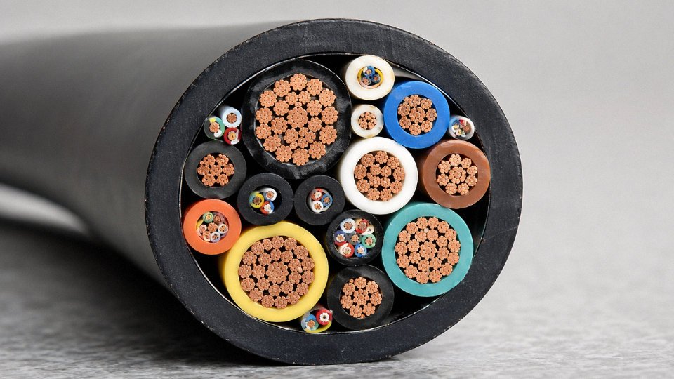
The conductors are only the beginning. Anti-tangle fillers — low-friction, usually specially profiled polymer cores — keep individual cores from migrating and crossing inside the sheath during repeated flexing. When cores tangle, you get uneven stress distribution and premature failure at the crossing points. The lay length of the cabling is controlled tightly; too short a lay and you get the “corkscrew effect” where the cable tries to rotate axially under bending, eventually unscrewing itself from terminations.
Sheath compound selection is where a lot of generic cable falls short. Polyurethane (PUR) and thermoplastic elastomer (TPE) sheaths are the workhorses here. PUR handles abrasion, cut-through resistance, and oil splash well — relevant in steel mills, automotive transfer lines, machine tool enclosures. TPE tends to offer better cold-temperature flexibility, down to roughly -40 °C in some formulations, which matters for outdoor crane installations in northern climates. Standard PVC sheaths, even flexible grades, simply don’t have the tear resistance or fatigue life for serious CF duty.
Bending Radius: The Number That Kills the Most Cables
Standard flexible cables are typically rated for a minimum dynamic bending radius of around 7.5× the cable’s outer diameter when moving. CF-rated drag-chain cables can be specified down to 4× OD, sometimes 5× depending on design. Violating the minimum bend radius — which happens more often than it should, usually because a drag-chain system was designed around available channel width rather than cable specification — is the single leading cause of premature CF cable failure in the field.
If you’re commissioning a drag-chain system and the chain geometry forces a tighter bend than the cable’s rated minimum, you either need a smaller OD cable or a different chain pitch. Ignoring this and hoping for the best is how you end up pulling a replacement cable through a fully loaded machine trough eighteen months into production.
Exceeding a continuous-flex cable's minimum bend radius is the leading cause of premature CF cable failure in drag-chain applications.True
Mechanical fatigue in fine-stranded conductors and insulation cracking at the flex zone accelerate sharply when the cable is forced into tighter radii than its construction is rated for, as documented in IEC TR 62102 flex test methodology and manufacturer flex test data.
Robotic Cable Construction
Robotic arm cables add torsion to the bending stress. A cable running from a robot’s base to its end-effector may see ±180° of rotation per meter of cable length across its working range. Standard CF cables aren’t designed for this. Robotic cables incorporate twisted pair or twisted trio core assemblies specifically to absorb torsional loads without the cores migrating or the shield distorting. The shielding itself is usually a foil-plus-braid combination — the foil maintains coverage during torsion while the braid contributes current-carrying capacity for the shield drain and handles the mechanical stress better than foil alone.
Crane, Hoist, and Festoon Cables
Festoon systems on bridge cranes, port gantries, and steel mill overhead equipment typically use flat-profile cable constructions. The flat geometry seats cleanly in festoon clips and prevents the cable bundle from swinging and tangling. These cables also need UV stabilization in the sheath compound for outdoor exposure — standard indoor PUR grades fade and crack in direct sunlight within a few years — and oil resistance for mill environments where hydraulic leaks and metalworking fluids are just part of the operating reality.
Selecting CF Grade: A Simple Cycle Count Framework
The practical selection rule is straightforward: estimate bend cycles per day, multiply by intended service years, and if the result exceeds roughly 1 million total cycles, you need a cable specifically validated for CF duty. A drag chain cycling 60 times per hour on a two-shift production line accumulates close to 1 million cycles in under a year. Standard flexible cable in that application is a maintenance problem waiting to schedule itself.
Jinda validates CF product families using in-house continuous flex test machines that run to 10 million cycles, following IEC TR 62102 methodology. That kind of test duration takes months per design iteration, which is why CF cable development cycles are longer and the resulting products cost more than standard flexible types. It’s a real cost difference, usually in the range of 20–60% over equivalent standard flexible cable, depending on cross-section and shielding complexity — but it’s a fraction of the downtime cost from a mid-production CF cable failure.
Industrial Data and Network Cables: Fieldbus, Industrial Ethernet, and Fiber Optic Variants
Most power cable engineers can spec a 3-core armored XLPE cable in their sleep. Ask them to size a PROFIBUS segment or route an EtherCAT cable past a VFD panel, and things get uncomfortable fast. That gap matters more each year. Industry 4.0 retrofits, IIoT sensor deployments, and distributed control architectures have pushed industrial data and network cables from a niche corner of procurement into a budget line that regularly surprises project managers who priced the job on power cable logic.
Fieldbus Cables: Impedance and Segment Length Are the Real Specs
PROFIBUS DP and PROFIBUS PA cables look similar to a screened instrument cable — until you check the datasheet. PROFIBUS DP requires a characteristic impedance of 120 Ω (±15 Ω across the 3 MHz to 20 MHz range), capacitance per unit length kept below roughly 30 pF/m, and a distinctive violet outer sheath that has been the standard long enough that site electricians treat violet as a visual stop signal meaning “don’t splice this into your signal loom.” DeviceNet uses a black sheath with color-coded inner conductors and is specified at 121 Ω ±1%. These aren’t advisory figures — a wrong-impedance cable causes reflections that corrupt data frames, and the fault rarely shows up cleanly on a multimeter. You get intermittent dropouts, especially at segment lengths approaching the 100 m (12 Mbps) to 1,200 m (93.75 kbps) limits for PROFIBUS DP.
AS-Interface is more forgiving on impedance but uses a flat, unshielded two-conductor profile with mechanically coded insulation to prevent reversed polarity — simple and robust, which is why it survives in harsh, wet production areas where connector-heavy topologies fail.
Industrial Ethernet: It’s Not Office Cable
PROFINET, EtherNet/IP, and EtherCAT all run on Cat 5e or Cat 6 twisted-pair infrastructure, but buying standard office cable and calling it “industrial” is a mistake that shows up within a year in any plant with cutting fluids, temperature cycling, or moving cable carriers. Industrial Ethernet cables for fixed installation typically use a PUR outer sheath rated for oil and UV resistance; drag-chain versions add finer stranding, a more flexible inner structure, and often a foil-plus-braid shield combination. Performance specifications run from 100 MHz bandwidth (Cat 5e) to 500 MHz (Cat 6A), and conformance testing under IEC 61784 covers both electrical performance and environmental resistance — not just the transmission parameters.
M12 D-coded connectors with IP67 sealing have essentially replaced RJ45 in serious industrial applications. The push-pull locking and full sealing matter far more than they seem when a connector sits in a wash-down zone on a food processing line.
Single-Pair Ethernet and IO-Link: Shrinking the Cable Bundle
SPE (Single-Pair Ethernet) based on IEEE 802.3cg (10BASE-T1L) is quietly displacing multi-conductor sensor cables in new installations. A single twisted pair carries 10 Mbps at up to 1,000 m, plus power via PoDL (Power over Data Line). For long sensor runs — conveyor position sensors, remote I/O drops in a large warehouse — replacing a 6- or 8-conductor cable with a 2-conductor SPE run cuts conduit fill and termination labor. IO-Link, which operates over standard 3-wire unshielded cables up to 20 m, handles the short last-meter sensor connections. Neither technology is universally adopted yet, but procurement managers on greenfield projects should get quotes on both.
Fiber Optic Cables: When Copper Simply Can’t Work
In environments with large VFD installations, smelting operations, or anywhere ground potential differences between buildings are unpredictable, fiber eliminates the noise problem entirely. Multimode OM3 and OM4 cables handle intra-plant high-speed links — typically up to 300 m at 10 Gbps — and the tight-buffered armored construction used in industrial fiber handles cable tray vibration and occasional foot traffic that would crack a telecom-grade fiber within months. For substation SCADA links or inter-building connections across a large site, single-mode OS2 reaches 40 km without a repeater.
Direct-burial industrial fiber needs a corrugated steel armor layer and a PE outer jacket; skipping either to save cost on the initial run almost always results in a repair job within two to three years, particularly in areas with significant ground movement or rodent activity.
EMC Shielding and Cable Routing: The Mistake That Costs the Most
Routing industrial Ethernet or fieldbus cables in the same cable tray as unshielded VFD power cables without physical segregation will cause elevated bit-error rates and intermittent communication faults.True
VFD output cables generate conducted and radiated high-frequency noise across a broad spectrum that overlaps directly with fieldbus and Ethernet signal frequencies. IEC 61000-5-2 specifies minimum separation distances and tray segregation practices specifically because co-routing is one of the most documented causes of unexplained PLC communication faults in industrial plants.
Foil shields alone work acceptably for fixed, low-vibration runs. Braided shields handle movement better and give coverage in the 85–98% range depending on braid density. Combined foil-plus-braid is the right choice for any data cable running within roughly 200 mm of a servo drive cable or a VFD output — closer than that, physical separation by a grounded steel divider is the more reliable fix than relying on shield performance alone.
The IEC 61000-5-2 guidance on separation distances is a starting point, not a guarantee. In practice, the actual interference level depends on VFD switching frequency, cable run length, and how consistently the shields are terminated at both ends to a low-impedance ground. Single-end shield termination — common when an installer is trying to avoid ground loops — significantly degrades high-frequency EMC performance and is the source of more mysterious fieldbus faults than most maintenance teams realize.
Specialty Industrial Cables by Hazardous and Extreme Environment: Mining, Oil and Gas, Marine, and High-Temperature Applications
Standard cables fail fast in genuinely hostile environments — not after years of gradual degradation, but sometimes within weeks. The cable categories below exist because engineers learned that lesson the hard way, usually through fires, explosions, or unplanned shutdowns that standard fire-resistant PVC simply could not prevent.
Mining Cables
Underground mining is probably the most mechanically punishing environment a cable will ever see. Roof falls, continuous contact with sharp rock edges, shuttle cars running over cables that shouldn’t have been there — the mechanical loading is relentless. On top of that, the presence of methane and coal dust creates explosive atmospheres that demand cables with verified anti-static and flame-retardant properties, not just nominal ones.
Construction typically uses extra-heavy-duty polychloroprene (PCP) or EPR sheaths, often 4–6 mm thick on the outer layer, with steel wire armor or steel tape armor underneath for crush resistance. Anti-static carbon-black compounds are blended into the sheath to prevent static charge accumulation — a real ignition risk in dry coal dust environments. Certification requirements vary by country: IEC 62441 and IEC 60502 cover the international baseline, MSHA approval is required for US underground mines, and GB 12972 governs Chinese domestic mining supply. Don’t assume a cable stamped “flame retardant” is actually mining-rated; the test standards are different, and procurement teams confuse these regularly.
Oil and Gas Cables — Onshore and Offshore
Hydrocarbons attack PVC insulation over time, and H₂S is worse — it degrades many polymer compounds faster than most published chemical resistance tables suggest, especially at elevated temperatures near process equipment. Offshore platforms add seawater spray, humidity cycling, and the requirement that a cable fire not generate toxic halogen gases in enclosed accommodation modules.
For these reasons, oil and gas cables typically use LSZH (low smoke zero halogen) or fluoropolymer insulation — PTFE and FEP being the usual choices where chemical resistance is the primary concern. Individual core screening is standard to manage the EMI environment around variable-frequency drives and subsea control systems. IEC 61892 governs marine and offshore installations and is the reference document most engineering contractors will ask for by default.
Subsea umbilical cables are a category unto themselves. A single umbilical might carry medium-voltage power cores, multimode fiber for control signals, and stainless steel hydraulic tubing for subsea actuators — all bundled and armored in one assembly. The integration engineering alone is non-trivial, and lead times for custom umbilicals can run 20–40 weeks depending on complexity.
Marine and Shipboard Cables
Classification societies — DNV, Lloyd’s Register, Bureau Veritas, ABS — each publish their own cable type approvals, and a cable approved by one society is not automatically accepted by another. Shipowners and shipyards know this; procurement teams buying for new builds should verify society approval before committing to a batch.
EPR insulation is preferred over PVC for shipboard work because it retains flexibility down to roughly −40 °C, which matters for deck-mounted wiring on vessels operating in northern latitudes. Flame spread testing per IEC 60332-3, smoke density, and toxicity testing are all mandatory. Salt-fog corrosion tests on connectors and armor are often required by project specifications even when not explicitly called out in the base standard.
High-Temperature Cables: Furnace, Smelter, and Glass Plants
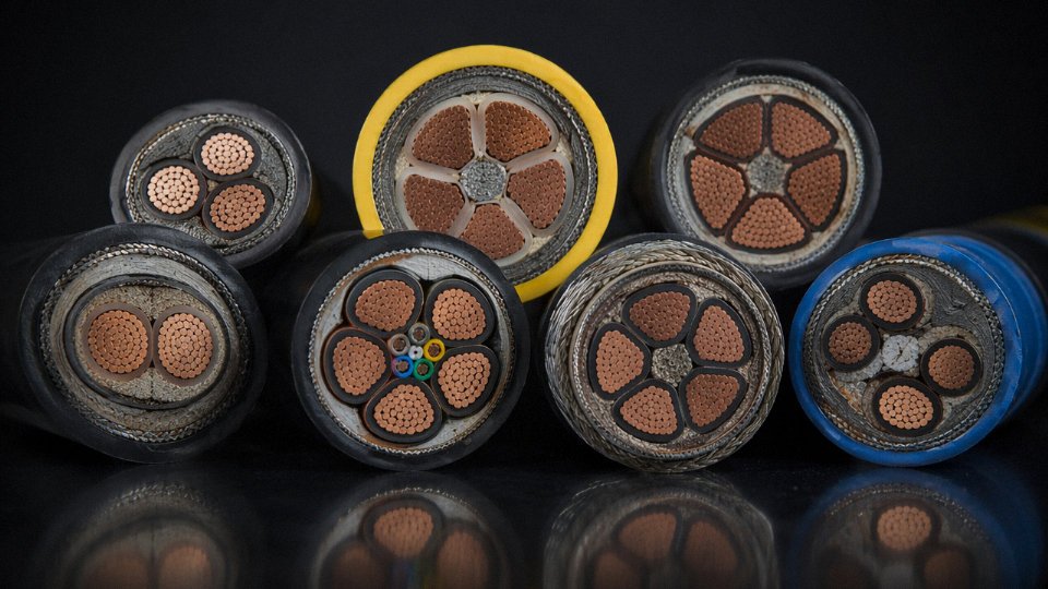
Silicone rubber insulation handles continuous service in the 150–200 °C range reasonably well. Beyond that, mineral insulated (MI) cable takes over — copper or stainless steel sheath packed with compacted magnesium oxide (MgO) insulation, capable of operating continuously at temperatures up to roughly 900–1,000 °C depending on sheath alloy. In a steel reheat furnace or a float glass line, MI cable is often the only viable option for thermocouple extension leads and burner control circuits near the combustion zone.
Fire survival circuits — emergency lighting, fire pump feeders, smoke extraction systems — use mica tape-wrapped construction rated per IEC 60331, which requires the cable to maintain circuit integrity for 90–180 minutes under direct flame. The mica layer survives after the polymer insulation has burned away.
Nuclear Power Plant Cables
Nuclear qualification is in a different tier of documentation from anything else discussed here. IEEE 383 and IEC 60780 require cable designs to demonstrate resistance to ionizing radiation, thermal aging, and design-basis accident conditions — typically a steam blowdown at elevated temperature. Material and manufacturing batch traceability must be maintained for the life of the plant, often 40–60 years. LSZH materials are essentially mandatory to prevent halogen release inside containment buildings during emergency scenarios.
Jinda holds third-party certifications for LSZH, armored, and flame-retardant cable families verified through independent test laboratories including KEMA, DEKRA, and SGS.True
Major international manufacturers supplying oil and gas, marine, and mining sectors routinely maintain third-party test laboratory certifications as a commercial and contractual requirement; Jinda's five-base manufacturing scale and 50-country supply footprint make these certifications operationally expected and verifiable through the named labs.
In practice, specialty cable procurement almost always requires submitting a project-specific technical data sheet to the manufacturer early — not after order placement. The difference between a standard armored LSZH cable and a fully mining-rated or offshore-qualified cable with the right third-party test reports can be 30–80% in unit price and 8–16 weeks in lead time, both of which will derail a project schedule if discovered late.
Conductor Materials, Stranding Classes, and Armor Types: How Construction Choices Affect Performance and Total Installed Cost
Cable specifications on a purchase order rarely tell the whole story. Two cables with identical voltage ratings and cross-sections can behave completely differently in service — one lasting 30 years, the other failing at a termination within 18 months — because of decisions made at the construction level that most procurement reviews never surface.
Copper vs. Aluminum: Not Just a Cost Trade-Off
Copper’s conductivity runs around 58 MS/m versus roughly 35 MS/m for aluminum, which means an aluminum conductor needs approximately 1.6× the cross-section to carry the same current. In practice, that translates to a larger overall cable diameter, bigger cable trays, and heavier conduit fill calculations. For a dense urban substation or a tightly routed machine room, that extra bulk matters. Copper also terminates more reliably — aluminum oxide forms quickly on exposed surfaces, and a poorly prepared aluminum lug joint in a switchgear panel is a slow-burn fire risk.
That said, aluminum has a genuine place. For high-current MV and HV transmission runs where weight dominates — overhead distribution lines, long underground feeder cables where pulling tension is a concern — aluminum’s weight advantage (roughly one-third the density of copper) and lower cost per kilogram swing the economics clearly. The decision isn’t about which metal is “better”; it’s about route length, installation method, termination frequency, and whether the installed-cost math actually pencils out.
Stranding Classes and Why the Wrong Class Destroys Cables Fast
IEC 60228 defines stranding classes that most engineers treat as a footnote. They shouldn’t. Class 1 is solid — appropriate only for fixed wiring where the cable never moves after installation. Class 2 is standard stranded wire, fine for junction boxes and cable trays in a static installation. Class 5 is the general-purpose flexible class used for portable equipment and panel wiring. Class 6 is extra-flexible, specifically intended for drag chains, reeling systems, and continuous-flex robotics duty.
Specifying Class 2 in a drag chain because it was cheaper, or because the difference wasn’t flagged at ordering stage, leads to work-hardening and conductor fatigue within months under continuous cyclic bending. The individual wires crack internally; resistance climbs; the insulation distorts around the failed conductors. By the time a fault shows up on diagnostics, you’ve usually already got intermittent signal errors or heat discoloration at connectors. A Class 6 cable in the same application will typically outlast Class 2 by a factor of five or more in bend-cycle terms, depending on the radius and cycle rate.
Using the wrong IEC 60228 stranding class in a continuous-flex application is one of the most common causes of premature cable failure in automated manufacturing lines.True
IEC 60228 Class 2 conductors are not engineered for cyclic bending; repeated flexing causes work-hardening and strand fracture in applications that require Class 5 or Class 6 construction.
Tinned Copper: Small Premium, Large Consequence
Tin coating on copper conductors adds somewhere between 3% and 8% to conductor cost, depending on tin thickness and market conditions. In a dry indoor environment, it’s arguably unnecessary. In marine installations, offshore platforms, food processing plants with regular washdowns, or any application where the cable jacket might be compromised by chemicals, that tin layer is the difference between a stable low-resistance termination and a creeping oxidation problem that eventually overheats a busbar connection or a terminal block. High-resistance joints in switchgear panels don’t announce themselves loudly — they just get warm, then warmer, until something trips or something burns.
Armor Selection: Match the Threat, Not the Habit
The default “just SWA it” approach wastes money in some applications and under-protects in others.
| Armor Type | Primary Threat Addressed | Typical Application | Key Limitation |
|---|---|---|---|
| Steel Wire Armor (SWA) | Mechanical impact + tensile pull-through | Direct burial, cable trays, vertical risers | Heavy; eddy currents in single-core AC |
| Steel Tape Armor (STA) | Radial crush resistance | Multi-core fixed wiring, tray installations | Low tensile strength; not for pulling |
| Aluminum Wire Armor (AWA) | Mechanical protection, single-core AC | Single-core MV power cables | Less robust than SWA against impact |
| Double Steel Tape Armor (DSTA) | Heavy crush, abrasion | Mining, tunneling, quarry environments | Stiff; difficult to terminate neatly |
| Wire Braid Armor | Flexibility + moderate mechanical protection | Flexible armored trailing cables | Not suitable for direct burial |
Single-core cables carrying AC are the one place where armor material selection directly affects energy efficiency. Steel armor around a single-core AC cable creates an eddy-current heating path — AWA avoids that entirely and is the correct specification for single-core MV feeders almost without exception.
Outer Sheath Compounds: Where Application Environment Drives the Call
PVC sheaths handle general-purpose indoor and outdoor duty adequately down to around -15 °C and up to 70 °C conductor temperature — cheap, available everywhere, and perfectly adequate for a lot of applications. XLPE pushes the conductor temperature limit to 90 °C continuous and offers better resistance to moisture ingress. PUR sheathing is worth specifying anywhere a cable gets dragged across machine beds, runs through chip conveyors, or lives in an environment with cutting oils and hydraulic fluid; its abrasion and cut resistance is genuinely superior to PVC in those conditions. LSZH compounds become essentially mandatory for confined spaces — tunnels, offshore topsides, public transit infrastructure — where halogen gases from burning PVC cable are the fire hazard, not just the flame itself. At the extreme end, fluoropolymer sheaths (PTFE, FEP) handle continuous temperatures above 200 °C and aggressive chemical environments, but at a cost premium that only makes sense when nothing else survives the environment.
Total Installed Cost: The Calculation Most Quotes Skip
A cable that’s 15% cheaper per meter but requires the next conduit size up, needs two-person termination teams instead of one, or fails at year eight in a 25-year asset adds cost that never appears on the original purchase order. Lifecycle cost should account for material cost, installation labor (which often exceeds material cost on complex routes), expected replacement interval, and the downtime cost of an unplanned failure. Over a 20- to 25-year horizon, the correctly specified cable — right stranding class, right sheath compound, right armor — almost always wins the total cost comparison even when it loses the unit price comparison.
International Standards and Certification Marks That Govern Industrial Cable Procurement
Procurement teams get burned most often not by choosing the wrong cable type but by accepting a cable that claims to be the right type without adequate proof. Standards and certification marks are the mechanism that converts a supplier’s claim into a verifiable technical commitment. Understanding which standard governs which application — and what a given mark actually certifies versus what it leaves unaddressed — is genuinely useful knowledge for anyone placing a significant cable order internationally.
IEC Standards as the Working Baseline
The IEC framework covers most of the ground. IEC 60227 governs PVC-insulated low-voltage cables for fixed wiring; IEC 60502 addresses extruded solid-dielectric cables in the 1 kV to 30 kV range and is probably the most-referenced standard in MV procurement globally. IEC 60228 defines conductor classes — class 1 (solid), class 2 (stranded), classes 5 and 6 (flexible) — and any quotation that omits conductor class is leaving room for a cheaper substitute to slip through. IEC 60332 covers flame propagation and comes in multiple parts: single-cable tests (Part 1 and 2), bunched-cable tests (Part 3), with A, B, and C categories depending on the volume of non-metallic material. Getting the wrong flame-test category in a cable tray installation is not a paperwork problem; it is a fire-spread risk. IEC 60529 defines IP ingress protection ratings applicable to assembled cable systems and terminations, and IEC 62067 governs EHV cable systems above 150 kV where the qualification test regime is considerably more involved.
Regional Standards and Where They Diverge from IEC
BS 6004 and the broader BS 7671 wiring regulations are the UK reference; they align closely with IEC for construction but carry specific UK-market temperature and installation requirements. VDE 0276 in Germany and NFC 32-102 in France are both largely harmonized with IEC 60502 for power cables but retain national annex requirements that can affect approved insulation compounds and drum marking. For North American projects, UL 83 and UL 44 govern thermoplastic and thermoset-insulated wire respectively, and CSA C22.2 handles the Canadian side — both diverge meaningfully from IEC on conductor temperature ratings and flame-test methodology. An IEC-compliant cable is not automatically UL-listed; the two systems test differently enough that dual qualification requires deliberate engineering effort and separate testing. Australia and New Zealand follow AS/NZS 5000, which is IEC-derived but with local deviations on short-circuit ratings and installation conditions.
GB Standards and Dual Compliance for Chinese-Sourced Cable
For buyers sourcing from Chinese manufacturers, GB/T 12706 is the domestic equivalent of IEC 60502 and is closely aligned — differences are minor and well-documented. GB/T 9330 covers control cables. GB 31247, China’s cable fire performance classification standard, has its own test regime that does not map one-to-one onto IEC 60332 categories, so buyers specifying flame performance should confirm explicitly which standard applies and request actual test reports rather than relying on printed cable markings alone.
GB/T 12706 is technically aligned with IEC 60502 but is not identical — minor differences exist in permissible conductor resistance tolerances and some insulation thickness requirements.True
GB/T 12706 was developed with reference to IEC 60502 but is a national standard with its own adopted values; international buyers should request a compliance comparison table from the manufacturer for critical projects rather than assuming full equivalence.
Third-Party Certification Marks and What They Actually Cover
CE marking for EU market access covers a cable’s compliance with applicable directives — primarily the Low Voltage Directive and the Construction Products Regulation — but CE is a self-declaration in most cable categories, not an independently audited certification. UKCA replaces CE for the UK market post-2021. UL listing for North America is different in character: it requires product testing at a UL-recognized laboratory and periodic follow-up inspections, which makes it a stronger independent verification. CCC (China Compulsory Certificate) is mandatory for cables sold into the Chinese domestic market and is issued after CNCA-authorized lab testing.
For marine applications, DNV or Lloyd’s Register type approval means the cable construction has been independently reviewed and tested to marine standards — relevant for offshore platforms and shipbuilding projects where a standard IEC cable would not be accepted. ATEX certification (EU) and IECEx (international) cover cables for explosive atmospheres; both require notified body involvement and cover the specific construction features — sheath compound, gland compatibility, and sometimes armoring — relevant to Zone classification.
Factory Audit and Quality System Credentials
ISO 9001 is the baseline quality management credential; ISO 14001 covers environmental management. For automotive cable supply, IATF 16949 is the relevant quality system standard. These credentials matter for supply chain risk, but they certify process controls rather than individual cable performance. The most effective risk-reduction tool for a large project order is witnessed factory acceptance testing (FAT) combined with third-party drum sampling: an independent inspector physically present during production, pulling sample lengths for conductor resistance measurement, insulation thickness verification, and spark testing. On orders above roughly 50–100 drums, this cost is almost always recovered by catching a single non-conformance before the cable ships.
Red Flags Worth Knowing Before You Sign the Purchase Order
Photocopied certificates without verifiable certificate numbers are common enough that they warrant a specific check procedure. Every legitimate UL, DNV, or IECEx certificate has a searchable number in a public database — spend three minutes verifying it. Certificates issued by laboratories without traceable accreditation to ISO/IEC 17025 are essentially worthless. A cable marking that claims “IEC 60502-2” but lists a conductor cross-section that measures 10–15% under-size on a micrometer — a problem found in field inspections more often than the industry admits — means the conductor resistance is higher than rated, which affects both ampacity and voltage drop calculations directly. The marking should also match the certificate’s described product exactly: sheath color, voltage designation, conductor class. Any mismatch is grounds to hold the shipment.
Verification takes time upfront. It takes far less time than a derating calculation after installation, or worse, a cable replacement during commissioning.
Industry-Specific Cable Selection Guide: Renewables, Rail, Petrochemical, and Building Automation
All the construction logic covered earlier — stranding classes, insulation chemistry, armor types, certification marks — only becomes useful when you map it against a real project. What follows is a working reference by vertical, not a textbook summary.
Renewable Energy: Solar PV and Wind
PV DC cables are a distinct product family that many general-purpose cable catalogs still handle poorly. Ratings must reach 1,500 V DC (the current IEC 62930 / EN 50618 baseline), with UV and ozone resistance verified by outdoor weathering tests — not just a marketing claim on a datasheet. Double insulation is mandatory; a single-insulated cable in a DC string circuit is a ground-fault waiting to happen, and DC arc faults don’t self-extinguish the way AC faults tend to. Halogen-free sheathing matters here because PV installations in many jurisdictions now fall under building fire codes, not just electrical codes.
Wind turbines add a mechanical problem that solar doesn’t have: continuous torsional flexing along the tower as the nacelle yaws. A properly rated tower cable handles ±600° of twist across a service life of tens of millions of cycles. Offshore wind adds salt air, high humidity, and in some cases partial submersion during commissioning or flooding events. Fire performance to IEC 60332-3-24 (vertical flame spread in bunches) is essentially non-negotiable given how a tower fire develops. Array feeder and export cables typically run in medium-voltage XLPE per IEC 60502-2, and cable sizing in offshore export circuits is often driven by reactive power losses over distance rather than thermal rating alone.

Jinda supplies solar and wind cables to projects across Europe, Southeast Asia, and the Middle East.True
Jinda's export documentation and project references confirm supply to customers in these regions, consistent with their stated 50-country supply footprint since 1987.
Rail and Mass Transit
Rolling stock cables operate under EN 50264, which governs everything from the conductor cross-section tolerances to the sheath elasticity. The fire-smoke-toxicity requirements under EN 45545 are the real gate-keeper: the standard classifies rolling stock into hazard levels (HL1 through HL3) based on whether passengers can self-evacuate, and at HL2 or HL3 most standard industrial PVC sheaths simply fail. Trackside signaling cables run under EN 50306 and face a different threat profile — rodent attack, ground movement, and inductive interference from traction power. Traction power itself runs at either 25 kV AC (most mainline electrification) or 750 V DC (urban third-rail systems), requiring cable designs well outside the normal LV power cable range. Buying a standard MV cable for a traction application without checking the specific mechanical and EMC requirements is a procurement error that sometimes doesn’t surface until commissioning.
Petrochemical and Chemical Process Plants
Area classification drives most of the cable selection here. Zone 1 and Zone 2 hazardous areas require ATEX-marked cables — and the marking alone doesn’t tell you everything; the cable construction needs to match the installation method and the specific gas group. DCS and SIS loop integrity depends heavily on individual pair shielding in instrumentation cables; a cable with overall shield only will pick up enough interference in a noisy substation environment to cause spurious alarms on a safety loop. Thermocouple extension cables for redundant temperature measurement are often triplexed — three pairs in one cable, each compensated for the specific thermocouple type (usually Type K or Type J in hydrocarbon service). For analyzer sample lines and reagent dosing areas, PTFE or FEP insulation is often the only chemistry-resistant option that holds up longer than a year or two.
Building Automation and Smart Infrastructure
Fire alarm cables with circuit integrity (CI) rating per IEC 60331 must maintain circuit operation at temperatures between 830°C and 1,000°C for 30 to 120 minutes depending on the application — this is a fundamentally different product from a standard alarm cable, and the difference only matters when a building is on fire. KNX bus cables for building management systems run at low voltages but require tight capacitance control to maintain signal integrity over long bus runs. LSZH sheathing throughout evacuation routes isn’t just a regulatory checkbox; toxic smoke from burning PVC cable in a stairwell is a well-documented cause of evacuation casualties. Structured cabling (Cat 6A) handles IP cameras, access control, and increasingly PoE-powered devices, all of which place combined power and data demands on the same conductor.
Data centers deserve a brief separate note. Flexible feed cables to busbar trunking need high current density in constrained underfloor or overhead routes. Cat 8 or single-mode fiber handles high-density top-of-rack connections where bandwidth headroom matters. A growing number of hyperscale facilities are moving toward 400 V DC distribution, which changes the DC cable insulation requirements compared to standard AC power distribution.
How Jinda Supports Project-Specific Cable Selection
In practice, the gap between a technically correct cable and an incorrect one often comes down to how early in a project the specification gets locked. Jinda’s technical sales teams work from standardized specification questionnaires that capture environment (indoor, outdoor, buried, submerged, hazardous area), mechanical duty (fixed, flexing, drag chain), voltage class, applicable standards, and certification requirements in a single workflow — before a quotation is issued. That process catches mismatches, like a customer requesting a standard control cable for a Zone 1 application, early enough to correct them without delaying delivery schedules.
Frequently Asked Questions About Industrial Cable Types
What is the difference between XLPE and PVC insulation, and when should I specify each?
PVC insulation is lower cost, straightforward to process, and rated for 90 °C conductor temperature at short-circuit conditions with a 70 °C continuous rating — perfectly adequate for most building wiring and light industrial fixed installations. XLPE (cross-linked polyethylene) is a chemically or radiation-cross-linked material rated at 90 °C continuous, with meaningfully lower dielectric losses, better resistance to moisture ingress, and improved performance in chemical environments. The cross-linking also prevents the slow thermal deformation you see in PVC at sustained high loads.
Specify XLPE for any medium-voltage cable regardless of installation type, for high-load LV feeders running close to rated current for extended periods, and for direct-buried outdoor runs where ground moisture is a real and constant factor. PVC still makes sense for indoor LV control wiring, panel wiring, and applications where cable cost is a significant line item and operating temperatures stay moderate. In practice, most MV and HV cable procurement today defaults to XLPE unless there’s a specific reason to do otherwise.
Can I use single-core armored cable instead of three-core armored cable for a three-phase circuit?
Technically, yes. In practice, if you specify steel wire armor (SWA) on single-core cables for a three-phase circuit, you’re creating a problem: the alternating magnetic field from each phase induces eddy currents in the ferromagnetic steel armor, generating heat that reduces current-carrying capacity and, in severe cases, damages the cable over time. The correct specification for single-core MV cables is aluminum wire armor (AWA) — aluminum is non-magnetic and doesn’t exhibit the same induction losses.
Beyond the armor material, always install single-core cables in trefoil formation and use trefoil clamps rather than flat formation with separate clamps. Flat formation with ferrous fixings is a classic installation error that causes inductive heating in the supporting metalwork, sometimes enough to discolor paint or degrade cable ties within months. Three-core armored cable sidesteps most of these issues and is generally simpler to install where route bends and space allow.
What does LSZH mean, and is it always better than PVC?
LSZH (low smoke zero halogen) cables are compounded to produce minimal smoke opacity and essentially no hydrogen chloride or other halogen acid gases when they burn. In a tunnel, a ship’s equipment room, an offshore platform, or a metro station, this matters enormously — HCl gas from burning PVC is immediately dangerous to personnel and corrodes electronics at concentrations well below what humans can detect by smell.
It’s not universally “better,” though. LSZH compounds are harder and less flexible than PVC at low temperatures, more sensitive to mechanical damage during installation in cold conditions, and noticeably more expensive — expect a cost premium of roughly 20–40% over equivalent PVC cables, depending on conductor size and the specific compound used. For outdoor industrial sites with good ventilation and no confined-space evacuation risk, standard PVC remains a rational choice.
How do I verify that a cable from an overseas supplier genuinely meets the specification on its datasheet?
The datasheet alone proves nothing. Request the complete third-party test report, including the accreditation body’s reference number — CNAS, ILAC-MRA signatories, BASEC, UL, or equivalent — so you can verify the report against the issuing laboratory’s public records. Ask for a drum sample before full shipment and have it tested independently for conductor resistance per IEC 60228, insulation resistance, and high-voltage spark testing. Then check the print legend on the cable sheath itself: the certified cable type designation, voltage rating, and standard reference should be printed legibly and should match the certificate exactly.
One thing experienced procurement teams do that newer buyers sometimes skip: weigh a cut sample of conductor against the declared cross-section. Undersized conductors — a persistent problem in the commodity end of the market — show up immediately in a resistance test or a simple mass-per-meter measurement.
Jinda provides third-party test reports with accreditation body reference numbers for all certified cable families upon request.True
This is standard practice for manufacturers supplying compliant cable to international projects under IEC, UL, or other regulatory frameworks, and is verifiable through the accreditation body's public certificate registry.
What is the maximum useful run length for a control cable before voltage drop or signal degradation becomes a problem?
It depends entirely on signal type. For 24 V DC digital I/O, a 2.5% voltage drop budget with 1.5 mm² conductors typically limits useful runs to somewhere in the 150–300 m range, depending on the load current drawn by the field device. For 4–20 mA analog loops, the limiting factor is total loop resistance — most transmitter/receiver combinations specify a maximum of 600–1,000 Ω, which translates to roughly 300–600 m with 1.5 mm² conductors before you start losing loop compliance.
Fieldbus protocols have their own defined segment lengths: PROFIBUS DP runs up to 1,200 m at 187.5 kbps on the standard cable type, dropping to 100 m at 12 Mbps. Foundation Fieldbus H1 specifies a 1,900 m maximum segment length under ideal conditions. Exceed these and you get intermittent communication faults that are genuinely difficult to diagnose — the kind that show up only under load or temperature variation and keep maintenance teams busy for weeks.
Does Jinda supply cables that meet both IEC and UL standards simultaneously?
Yes. Jinda produces dual-certified cable families carrying both IEC type approvals and UL listings, which is genuinely useful for international EPC contractors working on projects with mixed regulatory jurisdictions — an LNG plant being built by a US-led consortium in Southeast Asia under IEC electrical standards is a situation where this matters immediately. A single cable specification sourced from one supplier simplifies QA documentation, reduces the risk of substitution errors on site, and typically lowers total procurement cost compared to sourcing separate IEC and UL-listed products from different manufacturers.
What lead times should I plan for specialty industrial cable orders?
Standard LV power and control cables from Jinda’s stock programs ship within roughly 2–4 weeks for typical drum quantities. MV and HV cable orders — where conductor sizes, insulation wall thicknesses, and drum weights make stocking impractical — generally run 8–16 weeks from order confirmation, and the upper end of that range applies when third-party witness testing is required by the client or end-user specification. EHV cables and complex specialty constructions are individually quoted after design review; assuming a lead time without confirmation is the kind of planning assumption that delays commissioning dates.
If your project schedule is tight, discuss stock availability early. Waiting until the cable schedule is on the critical path to start procurement conversations is one of the more common and avoidable mistakes in capital project execution.
How to Evaluate and Partner with an Industrial Cable Manufacturer for Long-Term Global Supply
After working through voltage classes, conductor construction, armor types, and certification requirements, the real question becomes practical: how do you vet a manufacturer before committing to a multi-year, multi-country supply relationship? Getting this wrong costs more than a bad price. Substandard cable hidden inside conduit or buried underground can cause fires, unplanned shutdowns, and warranty disputes that dwarf any initial savings on unit cost.
The Five Pillars of Supplier Evaluation
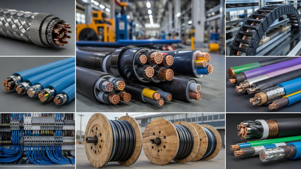
Manufacturing depth versus assembly. The first question to ask any cable supplier is where their process actually starts. A genuine manufacturer draws conductor from copper rod, compounds their own insulation blends, extrudes, strands, armors, and tests — all under one quality system. An assembler buys finished cores from third parties and re-reels or over-sheaths them. That distinction matters enormously for traceability when something fails at kilometer 47 of a subsea trench. Jinda operates five production bases across China totaling 470,000 m², covering the full chain from rod breakdown through finished cable testing. That’s not a marketing claim about floor space — it means process redundancy when one base has a maintenance outage or a regional logistics disruption.
Certification portfolio breadth. A supplier might hold IEC certification for low-voltage power cable and nothing else. That’s fine if that’s your entire scope, but EPC contractors working across Europe, the Gulf, Southeast Asia, and sub-Saharan Africa within a single project frame need a supplier whose certification portfolio actually maps to those destination markets and application classes. Verify that certificates are current, that the issuing body is accredited, and that the specific cable construction listed on the certificate matches what you’re ordering. Certificates for one conductor cross-section do not automatically extend to a different cross-section under the same type designation.
R&D and customization capability. Catalog products cover maybe 70–80% of industrial cable requirements. The remaining cases — a high-flex torsion cable for a wind turbine pitch drive, a combined power-and-fiber cable for a subsea ROV umbilical, a flame-retardant screened instrumentation cable rated for 130°C in a petrochemical heater area — require engineering. Jinda’s R&D center runs over 30 engineers whose work is specifically oriented toward non-standard applications rather than re-specifying existing product lines. That capacity matters when you’re six weeks from project commissioning and the catalog solution doesn’t quite fit.
Quality assurance infrastructure. In-house accredited laboratories, statistical process control on extrusion line parameters, and full material traceability from raw copper lot to finished drum serial number — these are the baseline. Ask for sample test reports before ordering, not after. If a supplier is reluctant to provide original test documentation, or if conductor resistance measurements on independently tested samples come back 8–12% above the declared value, walk away. Undersized conductors are one of the most consistently documented failure modes in substandard cable globally.
Conductor cross-sections on substandard industrial cables frequently measure below the declared nominal value on independent testing, increasing resistive losses and creating thermal hazards at rated current.True
This is a well-documented finding in multiple independent market surveillance studies and is one of the primary technical risks associated with low-cost cable procurement from unaudited sources.
Supply chain resilience. Volume project deliveries fail when a supplier has a single production site, thin raw material buffer stocks, and no established freight partnerships for drum shipments. For large-scale projects in Europe, the Middle East, or Africa, drum logistics alone require pre-arranged relationships with freight forwarders experienced in heavy industrial goods. Jinda maintains logistics partnerships covering these regions specifically, with consignment stock arrangements possible for fast-turnaround construction phases.
Red Flags in Low-Cost Supplier Evaluation
No original test reports. Reluctance to allow factory audits. Sheath print legend absent or citing incorrect standard references. Inconsistent sheath wall thickness across a drum length. These are not minor quality niggles — they are indicators of a systemic quality culture problem, and they show up exactly when project pressure is highest.
How Long-Term Framework Agreements Actually Work
Major EPC contractors and utilities typically structure cable supply around price indexing to LME copper (usually monthly or quarterly averaging), annual volume commitments that trigger capacity reservation on the manufacturer’s production schedule, and dedicated project engineers assigned to each framework customer. In practice, this means the customer gets price transparency without speculative margin, and the manufacturer plans production rationally rather than taking spot orders. For fast-turnaround project phases, consignment stock held at a regional logistics hub eliminates the 8–14 week lead time that otherwise derails installation schedules.
After-sales support is where the gap between a commodity vendor and a supply partner becomes visible. Joint commissioning assistance, TDR-based cable fault location support, and structured training for installation crews on bending radius limits, pulling tension, and correct termination technique — these services rarely appear in a price comparison spreadsheet, but they directly affect the cost of errors during installation.
Jinda’s project specification review service is a practical starting point for procurement teams evaluating a new supply relationship. Send a cable schedule or specification package; the technical team will respond with a detailed compliance review, proposed construction alternatives where relevant, and sample availability. For international procurement teams looking for a manufacturer with a verified 37-year track record, broad certification coverage, and genuine full-chain manufacturing depth, that’s the right first step.