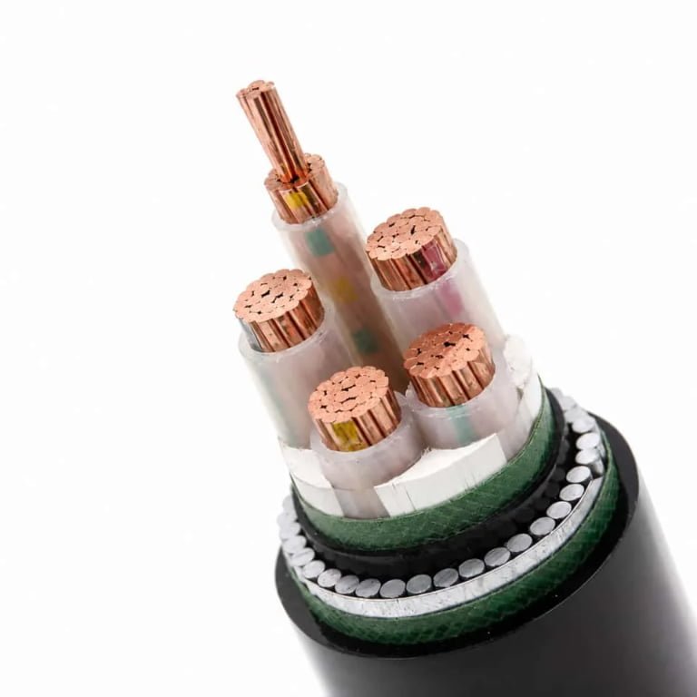
Pulling an unlabeled cable from a conduit and guessing its rating is one of those small decisions that can spiral fast — wrong insulation class means premature jacket failure, wrong conductor sizing means nuisance trips or, worse, a slow thermal fault that nobody catches until there’s smoke. Maintenance teams do it constantly, especially on aging installations where the original documentation has long since disappeared. The cost shows up later: unplanned downtime, a scrapped cable run, or a failed inspection that delays commissioning by weeks.
You identify a cable type by reading its outer jacket print, cross-referencing the conductor count and cross-section against IEC or AWG sizing standards, checking the insulation material and color coding, and confirming the voltage class marking — typically stamped as 0.6/1 kV, 3.6/6 kV, or higher. Together, these four elements tell you the cable’s application, temperature rating, and safe operating limits.
What makes this genuinely tricky is that the same physical cable can be acceptable in one installation and completely wrong in the next — a 0.75 mm² screened pair that’s fine for instrumentation in a mild environment has no business running near a furnace where jacket temperatures regularly hit 110 °C. The markings are there to prevent exactly that kind of mismatch, but only if you know how to read them.
Reading Cable Print Markings, Color Codes, and Surface Legends to Identify Type Instantly
The outer sheath of a cable is, in most cases, a data sheet you can hold in your hand. Manufacturers are required — under IEC, EN, NEC, and UL frameworks — to print the critical electrical and mechanical specs directly onto the jacket surface at regular intervals, typically every 500 mm to 1,000 mm depending on the standard and cable diameter. If you know how to read that print sequence, you can identify conductor cross-section, insulation material, voltage class, and applicable standard in under a minute without cutting anything open.
IEC and EN Surface Marking Conventions
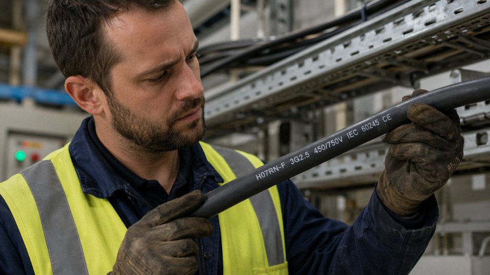
Under EN 50525 and the broader IEC harmonized cable system, the surface legend follows a structured sequence: manufacturer or brand identifier, the harmonic designation code, conductor cross-section in mm², and the relevant standard number. A typical legend might read something like H07RN-F 3G2.5 IEC 60245. Breaking that down: H = harmonized European designation, 07 = rated voltage 450/750 V, R = rubber insulation, N = chloroprene (neoprene) sheath, F = flexible stranded conductor, 3G = three conductors with one being the combined earth (the “G” tells you there’s a green-yellow ground core included), and 2.5 is the cross-section in mm².
The European designation codes are honestly more logical than they first appear. NYY is a PVC-insulated, PVC-sheathed power cable — N means German standard (VDE), Y is PVC insulation, the second Y is PVC outer sheath. NYMZ adds an intermediate metallic screen. ÖLFLEX is a brand name from Lapp that appears on flexible control cables; it’s not a generic designation, so don’t confuse the brand mark for a standard code.
The letter 'G' in an EN harmonic designation (e.g., 3G2.5) specifically indicates that one conductor serves as the protective earth conductor.True
In IEC/EN cable designation, 'G' means the stated number of conductors includes one green-yellow earth core, whereas 'X' would indicate no earth conductor is included in the count.
NEC and UL Marking Conventions in North America
North American cables follow a different logic. A THHN conductor jacket will be printed with the conductor gauge in AWG or kcmil, the insulation temperature rating (90°C dry in this case), voltage rating (typically 600 V), and the UL listing mark. USE-2 tells you it’s rated for underground service entrance at 90°C wet. MC cable — metal-clad — will show the circuit conductors, armor type, and whether it carries a separate equipment grounding conductor or relies on the armor itself.
When you need full specs, the UL White Book (UL’s General Information for Electrical Equipment Directory) is the reference. Cross-referencing a UL product category code, like XHHW or WTTC, against that directory gives you the full approved construction. In practice, most plant electricians don’t keep the White Book on the floor — but the product listing number on the cable jacket will pull it up on UL’s Product iQ database in about 90 seconds.
Color Codes: IEC, Regional Variants, and the Traps That Catch People
IEC 60446 specifies brown, black, and grey for L1, L2, and L3 phase conductors respectively, blue for neutral, and green-yellow for protective earth. That’s the current harmonized standard across most of Europe and adopted broadly in IEC-compliant plants worldwide.
The problem is legacy wiring. Older British installations used red/yellow/blue for phases and black for neutral — a scheme still common in facilities that haven’t been retro-fitted. Australian wiring historically used red for active, black for neutral, and green for earth, though AS/NZS 3000 has since harmonized closer to IEC. In China, the GB/T standard specifies yellow, green, and red for the three phases, with light blue for neutral and yellow-green for earth. In North American NEC work, black and red are common for ungrounded conductors, white or grey for neutral, and green or bare for ground.
Mixing these up when extending or connecting circuits is not a theoretical problem. It’s a source of real faults, particularly neutral-to-phase miswires that won’t trip a breaker but will destroy connected equipment.
When the Print Has Worn Off
Abrasion, UV exposure, chemical wash-down, or simply age will sometimes make the jacket legend unreadable. In that situation, photograph the cut cross-section end-on, next to a ruler or a coin for scale. The conductor count, their arrangement (bunched, sector-shaped, concentric), the insulation color sequence of each core, the presence and construction of any metallic screen or armor, and the sheath color together form a secondary identification fingerprint that’s usually enough to narrow the cable to one or two possible types. A sector-shaped conductor, for instance, immediately tells you you’re looking at a medium or large power cable — those shapes only appear above roughly 25 mm² or 35 mm² in most constructions, because there’s no manufacturing reason to sector-shape small conductors. Compare what you see against manufacturer cross-section drawings, which reputable suppliers publish in their technical catalogs.
One practical habit worth keeping: when a cable reel arrives on site, mark the cable type on the cut end with a paint pen before the jacket print gets obscured in conduit or tray. Takes five seconds and avoids a much longer troubleshooting session later.
Decoding Cable Construction Layer by Layer: Conductor, Insulation, Screen, Armor, and Sheath
Physical cross-section inspection is what you fall back on when the print legend is worn off, the drum tag is missing, or you’ve pulled an unlabeled cable from a conduit that’s been in the ground since the 1990s. Done methodically, it tells you almost everything — conductor material, flexibility class, voltage rating, environmental duty, and whether the cable was ever intended for the application it’s currently doing.
Conductor: Solid vs. Stranded, Copper vs. Aluminum, and Sizing by Measurement
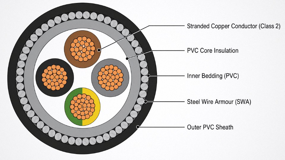
Start at the center. A solid conductor means IEC Class 1 — fixed wiring only, no repeated flexing. Stranded conductors range from Class 2 (a modest handful of wires, typical in fixed-installation power cables) up through Class 5 and Class 6, where you’re looking at very fine wire bundles that feel almost rope-like. Count the strands if you can; a 7-strand configuration is Class 2, while Class 6 flexible conductors often run 196 strands or more in larger cross-sections. This matters operationally — using a Class 2 cable on a trailing flex application will crack conductors within months.
Copper versus aluminum is usually obvious by color: copper is reddish-orange when freshly cut, aluminum is silver-white and noticeably lighter. Heft is a real tell — an aluminum conductor of the same cross-section weighs roughly 30% of an equivalent copper one. If the cross-section area isn’t labeled, measure the conductor diameter with a caliper and apply π×r²; for a stranded conductor, measure across the full bundle, then apply a lay factor correction of roughly 0.75–0.85 depending on how tightly the strands are packed.
Insulation: Material, Stiffness, and Thickness as a Voltage Proxy
PVC insulation is flexible, slightly glossy, and burns with dense black smoke — it’s the most common material you’ll encounter. XLPE is stiffer and off-white; you can’t easily deform it between your fingers the way you can PVC, and it handles sustained operating temperatures up to around 90°C for standard grades and higher for special compounds. EPR (ethylene propylene rubber) feels genuinely rubber-like and is typically darker in color, often used in mining cables and marine applications where flexibility at low temperatures matters. Silicone insulation is unmistakable — very soft, almost squishy, usually white or translucent, and capable of withstanding temperatures up to roughly 180–200°C.
Insulation thickness is a direct proxy for voltage class. Low-voltage cables (up to 1 kV) carry relatively thin insulation walls. As you move into medium-voltage territory (1–36 kV), the insulation becomes substantially thicker — sometimes dramatically so for the higher end of that range. If you’re measuring insulation wall thickness and it’s exceeding 5–6 mm on a single conductor, you’re almost certainly looking at medium-voltage or above construction.
Insulation wall thickness alone cannot confirm voltage class without also checking the cable standard it was built to.True
Wall thickness targets differ between IEC 60502, IEC 60228, ICEA, and other standards for the same nominal voltage, so a measurement must be cross-referenced against the applicable standard to be definitive.
Screening and Shielding Layers
A foil screen with a bare drain wire running alongside each insulated conductor is the signature of an instrumentation or data cable — the individual shielding tells you it was designed for signal integrity, not power. A collective copper tape wrapped around all cores together points toward a medium-voltage cable where the screen manages electric field distribution. Braided copper or tinned-copper screening over a flexible cable assembly is a different story: that’s industrial flex duty, prioritizing both EMI protection and mechanical resilience during continuous movement.
Armor Type and What It Reveals
Steel wire armor (SWA) with round wires is the standard for direct-burial single-core or multicore power cables — the round geometry handles tensile stress from installation and ground movement. Flat steel tape armor (STA) is more common on smaller multicore cables where radial crush resistance matters more than tensile strength. Aluminum wire armor (AWA) shows up where magnetic losses from steel armor would be unacceptable, particularly on large single-core AC cables. If you’re looking at a multicore cable with an oval cross-section and flat armor wires, that’s specifically engineered to keep the overall profile low — common in duct-installed instrumentation bundles.
Outer Sheath: Narrowing Down the Application
Standard black PVC (ST1 or ST2 grade) is everywhere. Polyurethane sheaths are tougher and more abrasion-resistant — if you’re looking at a trailing cable for a mobile machine or a drag chain assembly, polyurethane is the likely candidate. LSZH compounds are typically off-white, beige, or sometimes distinctively red depending on the manufacturer’s convention; they’re specified for tunnels, public buildings, and any enclosed space where halogen gas toxicity in a fire is a genuine concern. HDPE sheathing is harder and waxier to the touch than PVC and is almost exclusively a direct-burial or submarine service material. Each sheath material, taken together with what you found in the layers beneath it, builds a picture that usually narrows the cable’s identity down to a short list — sometimes just one.
Matching Voltage Class and Current-Carrying Capacity to Your Cable’s Physical Ratings
The printed legend on a cable sheath tells you a lot, but when that legend is worn off, the drum label is missing, or you’re auditing a legacy installation where documentation is patchy at best, you need to work backwards from physical evidence. Voltage class and current-carrying capacity can both be estimated — with reasonable confidence — from calipers, a reference table, and some knowledge of the IEC framework. This is the kind of verification that saves you from energizing the wrong cable.
Understanding the U0/U Voltage Designation
IEC cables carry a two-figure voltage designation that engineers sometimes misread. Take 0.6/1 kV: the first number, U0, is the rated voltage from any conductor to earth (or to the metallic screen), and the second, U, is the rated voltage conductor-to-conductor. So a 0.6/1 kV cable is designed for systems where the phase-to-earth voltage doesn’t exceed 600 V and phase-to-phase doesn’t exceed 1,000 V — your standard 400 V three-phase LV distribution network fits comfortably within that.
As you move up the voltage ladder, the designations are 3.6/6 kV, 6/10 kV, 12/20 kV, and 18/30 kV. Each step demands substantially thicker insulation and a different construction — screened cores become mandatory somewhere around the 6/10 kV class depending on the system earthing arrangement. Missing that distinction and installing a 0.6/1 kV cable in a 6/10 kV application is not a slow failure; it’s a rapid one.
Reading Voltage Class from Insulation Thickness
This is where calipers earn their place on the job. Insulation wall thickness is specified in IEC 60502 and related standards, and it scales predictably with voltage class. On a 2.5 mm² XLPE conductor, a 0.6/1 kV cable typically shows 0.7–0.9 mm of insulation per core. Measure 5.5 mm or more on a medium-voltage core and you’re almost certainly looking at 12/20 kV class. The relationship isn’t perfectly linear — it also depends on conductor cross-section, because larger conductors carry some electric stress relief inherently — but for a rough field classification, caliper measurements combined with the IEC 60502 insulation thickness tables give you a defensible answer.
In practice: strip back a short section of jacket carefully, expose a single insulated core, and use a micrometer or fine-tipped digital caliper. Measure at two or three points around the circumference; eccentricity in lower-quality cables can be surprisingly large.
IEC 60287 and What Actually Determines Ampacity
Current-carrying capacity is not a single number stamped on a cable — it’s a calculated result, and IEC 60287 is the methodology. The key inputs are conductor cross-section, the thermal resistivity of the insulation and surrounding medium, maximum allowable conductor temperature (90°C for XLPE, 70°C for standard PVC), ambient temperature, installation method, and grouping. Change any one of those and the rating shifts, sometimes dramatically.
As a working reference for copper XLPE cables at 90°C conductor temperature in free air, single-circuit installation:
| Conductor Cross-Section | Approximate Continuous Rating |
|---|---|
| 2.5 mm² | 25–30 A |
| 10 mm² | 63–72 A |
| 35 mm² | 125–145 A |
| 95 mm² | 235–255 A |
| 240 mm² | 420–475 A |
These figures assume free air, no bunching, and an ambient of around 30°C. Direct burial, grouped trefoil installation in a duct bank, or an ambient of 40°C+ — all of which are common in Middle Eastern and Southeast Asian projects — can reduce usable capacity by 20–40% depending on the specifics. Don’t use free-air ratings as your design basis without applying the IEC 60287 derating factors explicitly.
Aluminum conductors of the same cross-section carry roughly 78–80% of the current of equivalent copper conductors under identical installation conditions.True
This is consistent with the ratio of electrical conductivities — copper at approximately 58 MS/m versus aluminum at roughly 35 MS/m — and is reflected in IEC 60287 ampacity tables across the cross-section range.
Field Verification with a Clamp Meter or Thermal Camera
Calculating what a cable should carry is one thing. Confirming it during live operation is another, and the two checks together are far more reliable than either alone. A clamp meter on the live conductors tells you the actual load current; compare that against the rated capacity adjusted for your installation conditions. If a cable labeled as 35 mm² is running at 160 A in a grouped underground duct in a warm climate, something is wrong — either the rating calculation wasn’t derated properly or the cable cross-section is smaller than believed.
Thermal imaging adds a second layer. A cable running at or near its thermal limit will show elevated surface temperature along its length, and asymmetric heating between phases in a multicore cable often points to unbalanced loading or a connection problem rather than a cable sizing error. In my experience, a 10°C rise above neighboring cables in a tray is worth investigating before assuming the cable is simply “running warm.” It usually means something upstream in the identification or sizing process was wrong.
Using Cable Standards and Certification Marks to Confirm Application Suitability
A cable can pass every visual inspection and still be wrong for the job. The marking might be correct, the jacket color acceptable, the conductor size adequate — but if the certification doesn’t match the installation territory or application class, you’re looking at failed inspections, insurance voids, and in some jurisdictions, personal liability for the specifying engineer. This section is about closing that gap.
IEC and CENELEC Families: The Global Baseline
For most international projects, IEC standards form the starting point. IEC 60502 covers extruded solid dielectric power cables from 1 kV up to 30 kV — it’s the reference you’ll see cited on cables going into substations, industrial plants, and renewable energy projects across Europe, the Middle East, Southeast Asia, and Africa. IEC 60227 governs PVC-insulated cables for fixed wiring and flexible applications up to 450/750 V, while IEC 60245 covers the rubber-insulated equivalents — useful when you’re sorting out why two cables look similar but one is rated for higher mechanical abuse or elevated temperature.
Overhead aluminum conductors fall under IEC 61089, which specifies stranding, tensile properties, and conductor grades. Don’t confuse a bare overhead ACSR with a sheathed distribution cable just because both carry transmission voltages; the standards are entirely separate, and so are the testing regimes.
In Europe, the HAR mark (CENELEC harmonized) tells you the cable is approved under a harmonized European standard and accepted across all member states without re-testing. Absence of the HAR mark doesn’t automatically mean the cable is non-compliant, but it does mean you’ll need to verify national approval separately — something worth clarifying with your procurement team before a container of cable clears customs in Rotterdam.
North American Standards: UL, CSA, and NEC Article 310
The U.S. and Canadian markets run on a parallel system. UL 44 covers thermoset-insulated cables (XHHW-2, RHH, RHW-2), UL 83 covers thermoplastic types (THHN, THWN-2), and UL 1072 handles medium-voltage cables up to 35 kV. For Canada, CSA C22.2 is the relevant series, and dual UL/CSA listings are common for cables sold across both markets — look for the combined mark on the reel label.
NEC Article 310 doesn’t certify cables, but it controls how they’re sized in U.S. installations. The ampacity tables there tie conductor cross-section, insulation temperature rating, and installation method together. A cable certified to UL 83 but derated incorrectly under Article 310 conditions still creates a code violation. Procurement managers sometimes overlook this: certification and correct application are two separate questions.
GB/T Standards and Dual Certification for Export
Jinda’s manufacturing is based on Chinese national standards — primarily GB/T 12706 for medium and low-voltage power cables and GB/T 9330 for plastic-insulated control cables. These standards align closely with their IEC counterparts, but not identically; there are differences in conductor resistance tolerances, armor wire dimensions, and flame-test classification methods that matter when you’re writing a purchase specification.
For export projects, dual-certified products (IEC + GB/T) are tested against both sets of parameters, and the test certificate should explicitly state which standard each parameter was verified against. If a certificate only references GB/T on a project specified to IEC 60502, that’s a red flag worth raising before shipment — not after.
Cables carrying the HAR mark are accepted in all CENELEC member states without additional national re-testing for the harmonized characteristics.True
The HAR harmonization agreement between European national standards bodies allows cables tested and certified under the harmonized standard to be marketed across all member states; this is the explicit purpose of the CENELEC harmonization system.
Specialty Certifications: Marine, Mining, and Hazardous Areas
Some applications demand certifications that go beyond standard industrial ratings. KEMA (now part of DNV) and Lloyd’s Register both issue type approvals for marine cables, and a shipyard or offshore procurement spec will typically name one of them explicitly. DNV approval is particularly common on offshore oil and gas projects. If a cable is being specified for a vessel or floating platform and the certificate is missing marine type approval, no flag-state surveyor will accept the installation.
For mining applications in the U.S., look for MSHA approval (Mine Safety and Health Administration). Underground mining cables face mechanical abuse, explosive dust, and poor ventilation — a standard industrial flexible cable, even a good one, simply isn’t tested for those conditions.
ATEX (European) and IECEx (international) certifications cover cables intended for use in explosive atmospheres — Zone 1, Zone 2, and the mining-specific zones. These marks are issued at the cable level or at the system level depending on the hazardous area classification. In practice, many engineers check the terminal equipment’s ATEX cert and forget the cable feeding it; that’s a gap that shows up in audits.
Reading a FAT Certificate and Third-Party Test Report
The Factory Acceptance Test certificate is your last line of defense before cable leaves the factory. Know what to look for. Key parameters include:
| Test Parameter | What It Confirms | Typical Pass Criterion |
|---|---|---|
| Conductor DC resistance | Conductor cross-section and material purity | Per IEC 60228 or equivalent at 20°C |
| Insulation resistance | Dielectric integrity, absence of voids or contamination | Usually >100 MΩ·km minimum, often much higher |
| High-voltage withstand (AC or DC) | No breakdown at rated or elevated test voltage | Per rated voltage class, duration 5–15 min typically |
| Flame propagation | Self-extinguishing behavior | IEC 60332-1, -3, or equivalent |
The test report should state the standard tested against, the actual measured values (not just pass/fail), the test equipment calibration reference, and the witnessing lab or third-party inspector. A certificate that only shows “pass” without measured values is essentially useless for technical verification — push back and ask for the raw data sheet. Any reputable manufacturer supplies it without argument.
One practical caveat: third-party test reports from accredited labs (SGS, Bureau Veritas, TÜV, Intertek) carry more weight than in-house certificates, particularly for first-order procurement from a new supplier. For repeat orders with established quality history, FAT witnessed by your own inspector at the factory is usually sufficient. What matters is that somebody independent checked the numbers.
Identifying Specialty Cable Types: Fire-Resistant, Instrumentation, Marine, Mining, and Flexible Trailing
General-purpose power cable identification is relatively straightforward once you know how to read a surface legend. Specialty cables are a different story. They carry additional construction layers, application-specific color codes, and certification marks that follow entirely separate standards — and mistaking one category for another can mean a vessel fire suppression circuit failing during a drill, or a trailing cable on a shuttle car shredding itself within a shift.
Fire-Resistant Cables (IEC 60331, BS 6387)
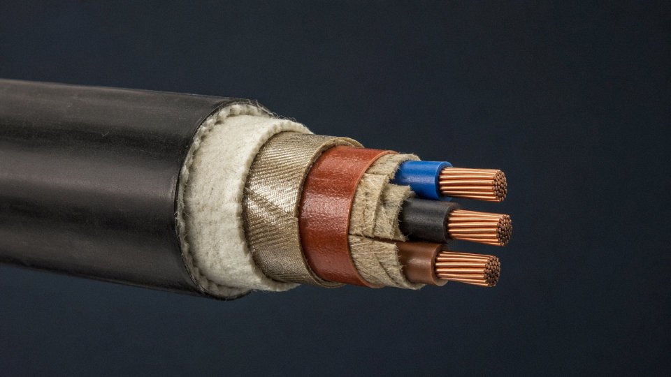
The defining feature of a fire-resistant cable is the mica tape wrapped around each individual conductor, sitting directly beneath the XLPE or low-smoke halogen-free (LSHF) insulation. Cut cleanly across the cable end with a sharp utility knife and look immediately at the conductor bundle: that shiny, silver-grey band — sometimes slightly flaky — is mica. It’s what maintains circuit integrity after the outer insulation has already burned away. You won’t see that layer on a standard XLPE power cable.
On the surface print, look for circuit integrity classification codes. BS 6387 uses a three-letter system: CWZ is the full classification (C = 950°C flame, W = water spray, Z = mechanical shock while burning). IEC 60331 cables may instead carry a time/temperature designation like 60331-21 or simply the legend FE180. If the print shows only LSHF or LSZH without any of these fire-integrity codes, that cable is low-smoke but not circuit-integrity rated — a crucial difference for escape route lighting or emergency pump circuits.
Instrumentation and Thermocouple Cables
Instrumentation cables reveal themselves almost immediately when you strip back the outer sheath: you’ll find individually screened pairs or triads, each wrapped in its own foil shield with a bare drain wire running alongside. The collective overall screen — usually a second foil layer or a tinned copper braid — wraps the whole assembly. That two-level screening architecture is the fingerprint.
Thermocouple extension cables add a color-coding dimension that trips people up constantly, because IEC 60584 and ANSI MC96.1 assign different colors to the same thermocouple type. Type K under IEC is green (positive) and white (negative), with a green overall jacket. Under ANSI, the same Type K is yellow (positive) and red (negative), yellow overall. If you’re on a plant that was built in phases by different contractors, you can easily have both conventions running in the same cable tray. Always cross-check the surface legend for the thermocouple type designation — don’t trust color alone.
Marine and Offshore Cables (IEC 60092 Series)
Marine cables often lack the steel wire armor you’d expect on a land-based medium-voltage cable. Weight matters on a vessel, so the armor is typically replaced by a tinned copper braid, which also provides some EMI screening. The outer sheath is CSP (chlorosulfonated polyethylene) or EPR — both oil-resistant and flame-retardant, noticeably stiffer and slightly rubbery compared to standard PVC. Look for the approval stamp on the reel label: Lloyd’s Register, Bureau Veritas, or DNV approval numbers confirm IEC 60092 compliance. No reel label, or a damaged one, means you need the original test certificates before that cable goes near a vessel installation.
Mining Cables (IEC 60502-1, MSHA, AS/NZS 2802)
Bright orange or red outer sheath, noticeably thick walls, and a heavier-than-expected cable for its conductor cross-section — those are the immediate field cues. Strip back the sheath and you’ll typically find an oversized earth conductor (often larger than a proportionate power circuit would require) meeting mine safety earth fault loop requirements, plus one or more smaller pilot cores color-coded for remote monitoring or earth continuity monitoring circuits. The sheath compound is usually chloroprene (neoprene) or a specialist EPR blend, chosen for resistance to oils, mechanical abuse, and the occasional dragging across rough ground. MSHA-approved cables carry a stamped approval number on the surface; AS/NZS 2802 cables will reference that standard directly in the print legend.
Flexible Trailing and Festoon Cables
Pick up a trailing cable and it feels different — more supple, almost alive compared to a fixed-installation cable of similar cross-section. That’s the Class 5 or Class 6 fine-stranded conductor construction: individual wire strands as fine as 0.1–0.2 mm, compared to the coarser strands in a Class 2 fixed-wiring conductor. The sheath is polyurethane or neoprene, both chosen for repeated mechanical flexing rather than UV or chemical resistance alone.
Surface markings on trailing cables sometimes include a maximum flex cycle rating or a minimum dynamic bending radius — something you never see on fixed-installation cable legends. A strain relief element, either a steel wire rope or a braided textile cord running through the cable center, is common on vertical festoon applications. If you’re looking at an unmarked cable and trying to determine whether it’s suitable for continuous flexing duty: check the conductor class first. A Class 2 stranded conductor in a festoon application will work fine initially and then fail by conductor fatigue in a matter of weeks, usually at the termination point.
Mica tape insulation under fire-resistant cable jackets maintains circuit integrity even after the outer insulation has fully burned away, which is why IEC 60331 and BS 6387 CWZ ratings are not interchangeable with LSHF or low-smoke ratings.True
Mica is a thermally stable mineral that retains its electrical insulating properties at temperatures above 1000°C. LSHF/LSZH compounds reduce toxic smoke but have no comparable fire-integrity performance — the two properties address different failure modes and are governed by entirely separate test standards.
Practical Field Identification Checklist: Seven Steps from Reel to Termination
You’ve pulled together everything from print legends to insulation chemistry. Now the question is what you actually do when a reel shows up on site with a faded sheath, a missing delivery note, or a drum label that’s been rained on. This workflow pulls it all together into a sequence you can hand to a QC inspector or run yourself.
Step 1 — Start With the Reel or Drum Label, Not the Cable
The drum label is the single most information-dense object on the delivery. It carries the full specification string, the applicable manufacturing standard, gross and net drum weight, cable length (typically stamped in meters), production batch or lot number, and — critically — whether the drum has passed factory acceptance testing. Photograph it immediately, before the drum moves, gets wet, or gets a forklift hook through it. In practice, labels are damaged more often than people expect. That photograph becomes your primary traceability record if anything goes wrong during installation.
Step 2 — Read the Sheath Print Legend Carefully
Work under good lighting; a head torch held at an angle works better than overhead fluorescents for reading embossed or worn print. If the ink is faded — common on cables that have sat in outdoor storage for a season or two — a UV lamp will often recover characters that appear completely gone under white light. Record every character in the exact sequence they appear. Don’t guess at a digit that’s rubbed off. Then decode the string against the relevant designation key: IEC 60502 for European-style LV/MV power cable, NEC/UL designations for North American projects, or GB/T standards for cables originating from Chinese production. A single transposed character — say, confusing “XLPE” with “PVC” insulation in the designation — changes the permissible temperature rating from roughly 90°C continuous up to 125°C or so, which matters enormously in engine rooms or industrial ovens.
Step 3 — Measure the Outer Diameter
A vernier caliper takes about ten seconds per measurement. Take readings at three points along a short cable section and average them. Cross-reference the result against the manufacturer’s published datasheet for your candidate specification. A measured diameter within roughly ±5% of the published value confirms you’re looking at the right cross-section and jacket build-up. A larger deviation usually means either the cross-section differs from what’s printed or the armor or bedding layer is non-standard — both worth investigating before you start pulling cable through conduit.
Step 4 — Make a Cross-Sectional Cut
Use a proper cable knife, not a utility blade you’re going to slip with. Cut cleanly, perpendicular to the axis. Count conductors. Identify any screen layer — whether it’s a copper tape, copper braid, or aluminum/polyester laminate — and check for armor (steel wire, steel tape, or aluminum wire). Then measure insulation wall thickness at three equidistant points around the core using a micrometer. Uneven walls, significantly thinner than the standard specifies, are a voltage class concern. For reference, a 0.6/1 kV XLPE cable typically carries an insulation wall in the range of 0.7 mm to 1.0 mm depending on conductor cross-section; medium voltage cables at 6/10 kV run considerably thicker, usually 3.4 mm to 4.5 mm.
Insulation wall thickness measured at a single point is sufficient to verify voltage class compliance.False
IEC 60502 and related standards require minimum wall thickness to be verified at multiple points around the circumference. A single measurement can miss localized thinning caused by manufacturing eccentricity, which represents a genuine dielectric risk under sustained service voltage.
Step 5 — Test Continuity and Insulation Resistance
A basic multimeter continuity check confirms conductor count and identifies drain wires or earth conductors that aren’t immediately obvious from the cut face. Follow that with a megohmmeter — 500 V DC for low-voltage cables, step up to 1,000 V DC for medium-voltage rated types. A healthy cable in good condition should read above 100 MΩ·km at this stage. Significantly lower readings on a brand-new drum suggest moisture ingress at a cut end, jacket damage from rough handling, or, occasionally, a manufacturing defect. Don’t install it and assume it’ll be fine.
Step 6 — Check Conductor Resistance Against IEC 60228
This step catches a problem that appears more often than it should: conductor cross-section that doesn’t match what’s claimed. Measure DC resistance with a bridge or precision multimeter and correct to 20°C using the standard temperature coefficient for copper (roughly 0.00393 per °C). A 2.5 mm² Class 2 stranded copper conductor per IEC 60228 should measure no more than 7.41 Ω/km. If your reading exceeds that by more than about 10%, the stated cross-section is likely wrong, or you’re looking at copper-clad aluminum — a material substitution that carries real consequences for ampacity calculations and termination hardware compatibility. CCA requires aluminum-rated lugs; standard copper compression terminals will cold-flow over time.
Step 7 — Reconcile With the Project Cable Schedule Before Installation
Map every finding — label data, measured OD, conductor count, insulation wall, IR, and resistance — against the project cable schedule or Bill of Materials line item. Any discrepancy, even a seemingly minor one like a conductor count that’s one off from spec, needs to go back to the supplier’s technical team before the cable goes in the ground or through a tray. Unlabeled or partially labeled cable is never compliant by assumption. The cost of a supplier query before installation is trivial. The cost of pulling out a misidentified MV cable from a buried duct, after energization, is not.
Common Cable Identification Mistakes That Cause Project Failures and How to Avoid Them
These errors show up repeatedly across industries — utilities, commercial construction, process plants, renewable energy sites. Most are avoidable. What makes them expensive is that they rarely cause an immediate, visible failure. They incubate.
Assuming Conductor Material from the Jacket
A cable with a grey or black PVC outer sheath gives you zero information about whether the conductor inside is copper or aluminum. None. You have to strip a tail, look at the conductor color (aluminum is silver-grey; copper is orange-pink when fresh), or check the print legend for an “A” prefix or the word “Al.” This matters enormously because aluminum’s conductivity runs around 61% that of copper, so an aluminum conductor needs roughly 1.5–1.6 times the cross-sectional area to carry equivalent current. Get this wrong in procurement and you may spec a 95 mm² aluminum cable thinking it performs like a 95 mm² copper cable. It doesn’t — it behaves closer to a 60 mm² copper equivalent. On a 400 A feeder, that’s a cable running hot, accelerating insulation aging, and eventually tripping breakers or worse.
THHN Is Not a Burial or Wet-Location Cable
THHN is everywhere in North American panel wiring and conduit runs because it’s cheap, widely stocked, and perfectly adequate in dry conduit. The problem starts when someone on a time-pressured job reaches for THHN because it’s rated 600 V and calls it done — using it for direct burial, underground conduit subject to water ingress, or outdoor wet locations. THHN’s thin PVC jacket absorbs moisture and begins breaking down within 12–24 months under those conditions. The insulation resistance drops gradually, long before any protection device trips. USE-2 or RHW-2 is the correct choice for those applications. The designations are printed on the cable; there’s no excuse to miss it if you look.
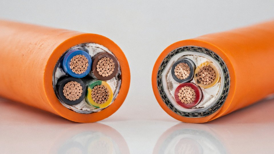
Orange Sheath ≠ Certified Solar Cable
Orange-jacketed DC cable is the de facto visual shorthand for PV wiring, and suppliers in several markets exploit that assumption. An orange jacket tells you nothing about UV stabilization, ozone resistance, or double insulation for DC systems. IEC 62930 and UL 4703 define what an actual solar cable must withstand. Non-certified cable on a rooftop installation degrades — the jacket chalks and cracks, insulation resistance falls, and in a worst case the cable becomes a fire ignition point. This degradation typically shows up within three to five years, which is well inside any reasonable module warranty period but often past the point where the installing contractor is still on the hook.
A standard orange PVC cable used in a rooftop PV installation without UV-stabilized compound or IEC 62930 certification will degrade significantly faster than a certified solar cable under continuous UV and thermal cycling.True
UV radiation and ozone attack non-stabilized PVC and PE compounds, causing jacket embrittlement and cracking. IEC 62930 (and its predecessor EN 50618) specifically tests for UV, ozone, and thermal aging resistance that standard building-wire compounds do not meet.
Correct Voltage Rating, Wrong Temperature Class
An engine room or industrial oven presents an ambient that can sit at 55–70°C continuously, before you add any self-heating from current load. A standard 70°C-rated cable in that environment is already operating near its ceiling at no load. Add conductor heating and you’re degrading insulation daily. Cables routed near steam lines or heat exchangers are a chronic source of this problem — often because the cable was correctly specified for the voltage, and nobody on the routing team checked the temperature column. The fix is straightforward: any location where ambient reliably exceeds 45°C should default to 90°C-rated insulation (XLPE or EPR), and above 100°C ambient, silicone-insulated types become necessary.
Ordering by Trade Name Instead of Full Designation
“SWA cable,” “armored cable,” “screened flex” — these terms mean different things in different countries and to different suppliers. Ordering ‘SWA’ without specifying BS 5467 or BS 6724 (the latter for LSZH sheath), conductor material, cross-section, voltage class, and insulation type is an open invitation to receive something that looks right on the reel but fails a compliance check. This happens more than procurement teams admit. The cable that arrives passes a quick visual: it has armor, it has a printed legend, it looks fine. But it may carry no recognized certification, use a thinner insulation wall, or have a conductor cross-section tolerance that pushes it to the low edge of what’s acceptable. Full IEC or UL designation in the purchase order is the only protection.
Unscreened Instrumentation Cable in VFD Circuits
Variable-frequency drives generate significant conducted EMI on the cable between drive output and motor, and also on any signal cable that shares a tray with those runs. Using unscreened instrumentation cable — even if the voltage and conductor size are correct — in that environment is asking for intermittent, difficult-to-reproduce sensor signal corruption. Analog 4–20 mA loops become noisy. PT100 readings drift. 0–10 V speed references produce erratic motor behavior. The insidious part is that this fault is extraordinarily hard to diagnose after installation because it’s not a wiring error, it’s a cable selection error, and the symptoms look like PLC programming issues or sensor faults. Screened, twisted-pair instrumentation cable with the screen grounded at one end only is the correct specification. Missing this detail on a VFD retrofit typically means pulling and replacing cable runs — expensive work that a correct spec prevents entirely.
Frequently Asked Questions About Cable Type Identification
How do I identify a cable with no visible markings?
Start with a steel rule and a calibrated micrometer. Measure the overall outer diameter, then carefully strip back the jacket to measure insulation wall thickness and count conductors. From the conductor diameter you can estimate the nominal cross-sectional area, then run a DC resistance test across a known length and back-calculate the actual CSA using IEC 60228 resistivity values. That test alone will tell you whether you’re dealing with a 16 mm² conductor or a 25 mm² — the two are frequently confused when outer diameters are similar.
The insulation material narrows things down further. PVC feels soft and slightly tacky at room temperature; XLPE is harder and springs back when you compress it. Rubber insulation has a distinctly elastic feel that neither of the others quite matches. None of this is lab-grade identification, but combined with the original purchase records or cable schedule for that installation batch, you can usually close the loop without destructive testing. If you genuinely have nothing to go on — no records, no markings, no recollection — treat the cable conservatively and assume the lower rating until you can confirm otherwise.
What is the difference between NYY and N2XY?
Both are IEC/VDE-convention low-voltage power cables rated 0.6/1 kV, and they look broadly similar on the outside. The difference lives in the insulation: NYY uses PVC on both the conductor insulation and the outer sheath, which limits the continuous conductor operating temperature to 70°C. N2XY substitutes XLPE insulation (that’s the “2X” in the designation) while keeping the PVC outer sheath, pushing the continuous temperature rating to 90°C. In practice, that temperature jump translates to roughly a 15–20% improvement in current-carrying capacity for the same conductor cross-section — meaningful when you’re sizing cable for a run that’s already marginal. If you’re procurement-side and someone offers you NYY as a direct drop-in replacement for N2XY, it is not. The ampacity tables are different and the thermal derating in a hot duct bank will compound the problem.
Can I tell copper from aluminum without cutting the cable?
A magnet won’t help — neither material is magnetic. What does work is a calibrated DC resistance measurement. Copper’s resistivity is roughly 1/58 S·m/mm² and aluminum’s is roughly 1/34 S·m/mm², so measuring resistance over a known length and dividing by the calculated CSA gives you a ratio that clearly points to one material or the other. The conductor will be noticeably lighter if it’s aluminum, and if you can access a termination lug or a visible cut end, aluminum is dull grey-silver whereas copper is the familiar reddish-brown — or greenish if it’s oxidized.
DC resistance measurement per IEC 60228 can differentiate copper from aluminum conductors without cutting or destructively testing the cable.True
IEC 60228 defines conductor resistance limits based on known resistivity values for copper and aluminum. Measuring resistance over a known length and cross-referencing against these values reliably identifies the conductor material from electrical data alone.
How do I verify a cable’s voltage rating without the original test certificate?
A high-voltage insulation tester — a hipot tester — is your field tool here. IEC 60502-1 specifies a proof test voltage of 3.5 kV AC for 5 minutes on a new 0.6/1 kV cable. For an in-service cable, use roughly 80% of that figure to avoid stressing aged insulation unnecessarily. A cable that holds this test without breakdown or significant leakage current confirms insulation integrity at the stated voltage class. This is not a substitute for the original factory test certificate in a formal handover, but for site verification or maintenance checks it’s a practical and widely accepted method.
What does LSZH mean on a cable jacket, and how do I recognize it?
LSZH stands for Low Smoke Zero Halogen. The compound typically feels slightly stiffer than standard PVC and is often light grey or off-white rather than the deep black or dark grey typical of PVC-jacketed cables. A brief, controlled flame exposure produces white smoke rather than the thick black smoke of burning PVC — though you probably don’t want to be doing flame tests on installed cable as a routine identification method. The reliable field identifiers are the surface print designations: “LSZH”, “LS0H”, or “LSNH”, often accompanied by a reference to IEC 60332-1 flame-test compliance or IEC 60754-1 for halogen acid gas content. If you need chemical confirmation, the IEC 60754-1 acid gas test is the standard. In tunnels, offshore platforms, and data centers this distinction genuinely matters — burning PVC in a confined space is a serious toxicity and corrosion hazard beyond the fire itself.
How do armor types indicate intended use?
Steel Wire Armor (SWA) uses round steel wires laid helically over the inner sheath — it’s the standard for direct-burial distribution cables and anywhere mechanical impact is a real risk. Steel Tape Armor (STA) uses flat overlapping steel tapes, which gives moderate crush resistance and suits indoor installation or duct-laid runs where the armor is mainly there for rodent protection or cable management. Aluminum Wire Armor (AWA) appears on single-core cables specifically because steel armor on a single-core AC cable would create a shorted turn in the magnetic field, generating eddy current heating that wastes energy and can damage the cable over time. So if you cut a single-core cable and see aluminum wire armor rather than steel, that’s a deliberate design choice, not a cost-cutting substitution.
Are conductor color codes globally standardized?
Partially, and the gaps cause real problems. IEC 60446 defines brown/black/grey for phases and blue for neutral in European harmonized systems, with green-yellow reserved for protective earth. North America uses black, red, and blue for phases in a three-phase system, white or grey for neutral, green for ground. China’s GB/T 6995 aligns broadly with IEC practice. The complication is legacy installations — UK sites wired before the 2004 harmonization used red, yellow, and blue for phases, and black for neutral, which directly conflicts with IEC 60446 where black is a phase color. On any installation more than roughly 20 years old, color alone is not enough. Cross-reference with the surface print legend and, if there’s any doubt, take a resistance measurement before you assume which conductor is which.
How Jinda’s Global Supply and Technical Support Infrastructure Helps You Specify the Right Cable Every Time
Getting the identification right is only half the job. The other half is sourcing a cable that actually matches what you’ve specified — and that comes with documentation solid enough to satisfy a project owner, a customs inspector, and your own QC team simultaneously. That’s where supply chain structure matters as much as technical knowledge.
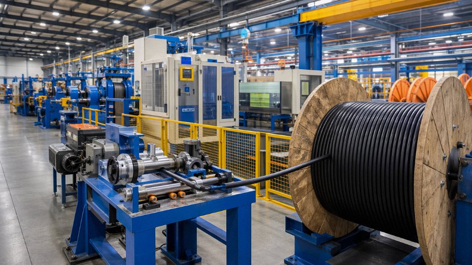
Jinda operates five production bases across China, and they’re not interchangeable facilities running the same product lines. Power cables up to 500 kV — the kind that require precisely controlled XLPE insulation extrusion under dry-cure nitrogen — come from dedicated high-voltage manufacturing lines with the footprint and process control that voltage class demands. Control and instrumentation cables, fire-resistant and LSZH types, and marine or offshore cables are produced on separate lines configured for the tighter dimensional tolerances, specialized compound recipes, and multi-core screening geometries those products require. Overhead bare conductors — ACSR, AAC, AAAC — run through stranding and tensioning equipment that simply isn’t part of a power cable plant. For a procurement manager putting together a bill of materials that spans, say, a substation build-out with HV feeders, instrumentation trays, fire-rated circuits in the control room, and an overhead distribution tie-line, having a single qualified supplier cover all of it cuts vendor qualification time considerably and eliminates the coordination friction between multiple delivery schedules.
Dual-Certification and Third-Party Test Documentation
Jinda's standard export products are produced under both IEC compliance and GB/T quality systems, with third-party test reports from accredited laboratories available per batch.True
This dual-certification approach is consistent with Jinda's stated manufacturing scope serving 50+ countries, where IEC compliance is required for international project approval while GB/T governs domestic Chinese production standards.
Most international project specifications demand IEC compliance, but Chinese factory audits and domestic trade documentation run on GB/T. Jinda produces to both simultaneously rather than treating them as separate certification tracks. Practically, this means you’re not waiting for a special production run or a separate test batch when your project owner asks for IEC 60502 compliance on a medium-voltage cable that’s also being supplied to a domestic end user. Third-party test reports from accredited laboratories are available per production batch — useful for customs clearance in markets that scrutinize cable imports, and essential when a project owner or EPC contractor requires independent test evidence rather than manufacturer declarations alone.
Pre-Shipment Identification and Traceability Packages
One thing that causes real problems on large cable projects is drums arriving on site with incomplete or ambiguous labeling — you’ve read about that risk throughout this article. Jinda’s standard pre-shipment documentation package addresses this directly. Each drum ships with a label carrying the full IEC designation, voltage class, conductor cross-section, insulation and sheath material codes, and the exact meter length on that drum. Individual reel test certificates travel with the shipment. The packing list breaks down meter lengths per drum, which matters when you’re allocating cable to specific circuits during installation. Every drum carries a traceability code linking it back to the production batch, the raw material certificates for conductor and compound, and the factory test records — so if a question arises six months into a project, you’re not hunting through paper files.
Technical Support That Reduces Specification Risk
Jinda’s technical support team works with international customers on cable schedule review, cross-referencing between IEC, UL, and GB standards, and site-specific derating calculations for burial depth, grouping, and ambient temperature — exactly the kind of analysis where specification errors tend to originate, as covered earlier in this guide. In practice, submitting a cable schedule for technical review before issuing a purchase order takes a few days and can prevent the kind of substitution or rating mismatch that costs far more to fix after installation.
If you’re working on a project that requires any combination of the cable types covered in this article, the straightforward path is to request product datasheets, submit your cable schedule for review, or contact Jinda’s export sales team for a project-specific quotation. With 37 years of manufacturing history, 470,000 m² of production capacity across five bases, and an active supply relationship with customers in more than 50 countries, Jinda is structured to support both immediate procurement needs and long-term supply partnerships — at the scale and documentation standard that international projects require.