Cutting into a wall blind is one of those jobs where the downside is wildly disproportionate to the few minutes it takes to do it properly. A drill bit through a live 230 V circuit means a tripped breaker at best, a burned-out tool or a flash burn at worst — and if you’re on a commercial site, you’re also looking at unplanned downtime, an incident report, and quite possibly a rework cost that dwarfs the original task. The frustration is that the cables are there, somewhere behind the plaster, and without the right method you’re essentially guessing.
To detect power cables in walls, use a non-contact AC voltage detector for quick live-wire checks within roughly 10–50 mm of drywall surfaces, a professional cable avoidance tool (CAT) operating at 50 or 60 Hz for positional accuracy to within about ±20 mm, or ground-penetrating radar for concrete and masonry where depth can reach 300 mm. Combining at least two methods significantly reduces false negatives.
What surprises most people — including experienced site supervisors — is how much the reliability of each method depends on factors that have nothing to do with the tool itself: whether the circuit is actually under load at the time of scanning, the wall construction type, even whether the cables are screened or run in steel conduit. The method that worked perfectly last week in a plasterboard partition may give you almost nothing in a reinforced concrete wall. Understanding why that happens is what separates a safe, confident scan from a lucky one.
Understanding What You Are Actually Detecting: Cable Construction, Shielding, and Signal Signatures
Before you pick up any detection tool, it helps to understand what that tool is actually responding to — because “detecting a cable” is not one single physical phenomenon. Depending on the tool and the cable, you might be sensing an electric field gradient, a low-frequency magnetic field, a ferromagnetic mass, or a radar reflection off a cylindrical object. Get the physics wrong and you will either miss cables entirely or chase ghost signals in the wall for twenty minutes.
The Electromagnetic Field a Live AC Cable Produces
A live AC cable radiates an alternating electric field at mains frequency — 50 Hz in most of the world, 60 Hz in North America and parts of Japan. The field strength at the wall surface depends heavily on how much current the cable is actually carrying at the moment of scanning. A lightly loaded 1.5 mm² lighting circuit pulling 2–3 A produces a noticeably weaker field than a 6 mm² ring main under full kitchen load. AC voltage detectors typically respond through drywall at distances of roughly 10–50 mm, but that upper end assumes a reasonably loaded circuit and a sensitive instrument — don’t count on 50 mm if the circuit is feeding a single standby lamp.
Voltage level matters less than you might expect. A 230 V domestic circuit and a 400 V three-phase feed both produce detectable fields, but the phase relationships in a three-phase cable tend to cause partial field cancellation between conductors, which reduces effective detection range somewhat.
Why Shielded and Armored Cables Are a Problem
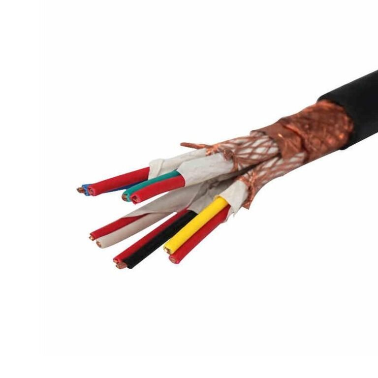
Steel-wire-armored (SWA) cable — the stuff you typically see in outdoor runs, underground feeds, and industrial plant sub-mains — creates a real detection headache. The steel wire layer acts as a partial Faraday shield. It does not completely suppress the EM field, but it attenuates it enough that an AC voltage detector may read nothing at all through a plastered wall, even on a fully loaded circuit.
Screened instrumentation cables with foil or braid shields behave similarly. In practice, SWA and screened cables are best located with a CAT tool operating in passive 50/60 Hz mode rather than a simple proximity detector, and even then you are partly relying on the magnetic signature of the steel armor itself — ferromagnetic metal scanning, not electric field sensing.
Conductor Material and Cross-Section
Copper and aluminum conduct differently, but from a detection standpoint the bigger variable is cross-sectional area. A 300 mm² aluminum busbar feeder has a physical mass that a metal-detection mode CAT tool reads clearly. A 1.5 mm² copper twin-and-earth, by contrast, produces a much smaller magnetic anomaly — close enough to background noise in some older lath-and-plaster walls that the signal gets buried. Professional cable avoidance tools running in active signal mode can locate live cables to within roughly ±20 mm in standard plasterboard, but that accuracy degrades in older, denser wall construction or where cable runs are congested.
Jacket and Insulation Materials
PVC, XLPE, and LSZH jackets are all essentially transparent to both electromagnetic field detectors and ground-penetrating radar. The jacket does not meaningfully attenuate the signal you care about. What it does affect is the outer diameter and physical profile of the cable — relevant for radar interpretation, less so for EM detection.
Flat twin-and-earth cables, which are standard in UK residential wiring, have an asymmetric cross-section that produces a slightly different radar reflection pattern compared to a round multicore. GPR units capable of resolving buried objects to around 5 mm in concrete can, in principle, distinguish profile shapes — useful when you are dealing with a congested wall and need to separate a data cable from a power circuit.
The De-Energized Cable Problem
Here is where people get into trouble. A de-energized cable — circuit breaker off, nothing drawing current — produces no electric field whatsoever. An AC voltage detector will not see it. Even a loaded-signal CAT tool will miss it unless the cable has ferromagnetic armor to generate a passive magnetic response.
A standard non-contact AC voltage detector will reliably locate a de-energized power cable in a wall.False
Non-contact voltage detectors respond to the electric field produced by an energized, alternating-current conductor. With the circuit breaker off and no current flowing, no usable field is present and the detector will show no response, regardless of cable proximity.
If you genuinely cannot energize the circuit — say, you are working on a decommissioned section of a building — you need either a CAT tool with a signal generator (apply a tracer frequency to the conductor directly) or a GPR scan. Relying solely on a voltage detector in that situation is how people drill through feeds they assumed were dead but were actually just lightly loaded and below the detector’s threshold. In practice, always combine tools on any job where the cable status is uncertain.
Non-Contact AC Voltage Detectors and Live-Wire Tracers: Best Use Cases and Correct Technique
How NCV Detectors Actually Work
A non-contact voltage (NCV) detector doesn’t touch anything — it senses the capacitive coupling between the AC electric field radiating from a live conductor and the probe tip’s internal electrode. That field exists even through drywall, plaster, or a thin layer of paint. The detector completes a tiny capacitive circuit: live wire to probe tip, through the internal circuit, out through your body to ground. No physical contact required.
Most pen-type detectors ship with at least two sensitivity settings. Low sensitivity is typically calibrated around 12–50 V — useful for confirming a wire is live at close range without false triggers from neighboring circuits. High sensitivity can respond to fields from conductors carrying mains voltage at distances of 10–50 mm through standard drywall, though that range depends heavily on the load on the circuit, the detector model, and whether the cable has any shielding braid. A lightly loaded circuit on a screened cable might barely register at 20 mm; a heavily loaded unshielded twin-and-earth cable might trip the alarm through 40 mm of plasterboard without any difficulty.
Scanning Technique: Slow Down More Than You Think
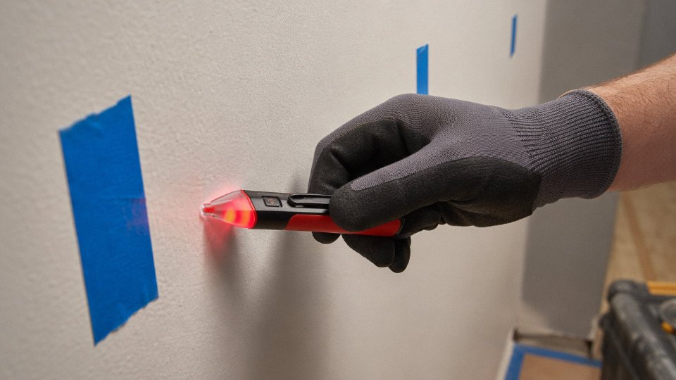
The single most common mistake is moving too fast. In practice, 25 mm per second is the right pace — that sounds painfully slow until you miss a cable at 50 mm per second and drill into it. Hold the probe tip flush against the wall surface or as close as the wall texture allows. Make horizontal passes first, spaced about 20–25 mm apart vertically. When you get a positive indication, mark the edge of the response with painter’s tape on both sides, then do a perpendicular pass to confirm. The centerline of those two tape marks is your best estimate of the cable run.
Overlapping your passes matters. The detector’s response zone isn’t a sharp line — it’s a gradient. You can miss a cable entirely if you space your sweeps too far apart, especially on higher sensitivity settings where the field bleeds out and the peak is harder to pinpoint.
Plug-In Circuit Tracers: Following a Specific Circuit
For tracing a known circuit — say, from a breaker through the wall to a run of outlets — a plug-in transmitter and receiver pair gives you much more control than a basic NCV pen. The transmitter plugs into any outlet on the target circuit and injects a specific signal frequency onto the wiring. The handheld receiver then picks up that frequency as you sweep the wall, letting you follow that circuit’s path rather than detecting every live wire in the building.
This is genuinely useful when you’re trying to map a wall before adding a new outlet box, or confirming which direction a circuit routes before a contractor cuts an opening. The receiver response is directional enough that you can trace a circuit run up a stud bay and across a ceiling cavity with reasonable confidence.
Signal Loss Through Different Wall Materials
Wall material has a significant effect on detection reliability.
| Wall Type | Typical Signal Attenuation | Practical Reliability |
|---|---|---|
| 12 mm plasterboard / drywall | Low | Good — NCV reliable on live circuits |
| 25 mm lime plaster over brick | Moderate | Usable, use high sensitivity |
| 100 mm solid brick | High | Marginal — confirm with second method |
| Reinforced concrete (150 mm+) | Very high | NCV usually ineffective; use GPR |
Metallic foil-backed insulation boards are a particular trap — the foil itself acts as a reflector and can cause a continuous alert across the whole surface even with no cable present. Fluorescent lighting ballasts and variable-speed motor drives both generate strong EMI that will light up a sensitive detector from a meter away. If you’re scanning near a switchboard, a fluorescent fitting, or any inverter-driven equipment, switch to low sensitivity and recheck.
NCV detectors can reliably locate de-energized cables in wallsFalse
NCV detectors work exclusively by sensing the AC electric field around a live, energized conductor. A cable with the breaker off, or any cable that is permanently de-energized, produces no electric field and will not trigger an NCV detector regardless of sensitivity setting.
What NCV Tools Cannot Tell You
Lateral position is approximate — expect ±20–30 mm at best from a basic pen detector, depending on wall depth and cable load. Depth is essentially unknown; the tool tells you a cable is there, not whether it’s 10 mm or 60 mm behind the surface. And as just noted, a dead circuit is completely invisible.
In practice, NCV and circuit tracer results should always be cross-checked with a second method — typically a combined stud/metal/live-wire scanner — before any drilling or cutting. Treat NCV detection as the first pass that rules out obvious hazards and narrows the search area, not as a clearance certificate on its own.
Stud Finders With Metal Detection Mode and Dedicated Cable Avoidance Tools (CAT): Performance Comparison
How Stud Finders Actually Work — and Why the AC Mode Is a Different Animal Entirely
Most people treat a multi-function stud finder as a single device that does several related things. In practice, the two core functions — stud detection and AC wire detection — operate on completely different physical principles and have almost nothing to do with each other.
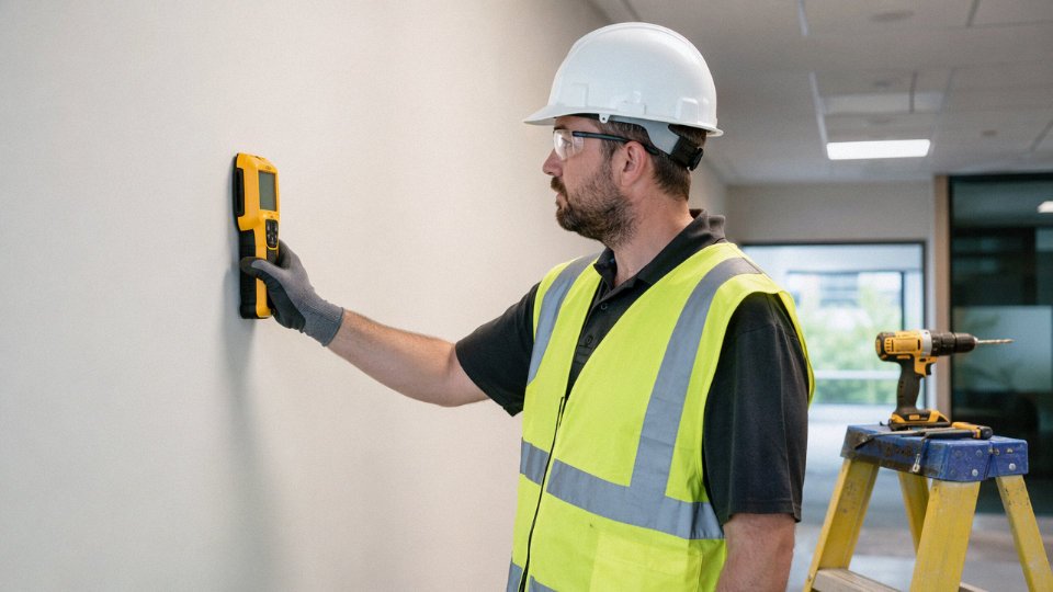
The stud-detection function is capacitive. The sensor measures the dielectric constant of the material directly behind the wall surface. A timber stud, a concrete block, or a metal channel all produce a measurable shift in that capacitance as you slide the tool across the wall. Depth penetration depends on sensor plate size and wall material, but most consumer units reliably find studs within roughly 20–40 mm of plasterboard or drywall. Beyond that, results get inconsistent — especially near moisture or dense insulation.
The AC wire detection mode is something else. It senses the electric field radiating from a live, energized conductor. No current flow required — just the voltage gradient that a live cable maintains continuously. That signal can penetrate 10–50 mm of standard drywall, depending on the cable’s load condition and the detector’s sensitivity threshold. The two modes share a housing, but they’re independent systems responding to independent phenomena.
That distinction matters operationally. A cable tucked between studs may trigger the AC mode but show nothing on stud detection. A metal pipe running parallel to a stud may confuse the density sensor without triggering the AC circuit. Always sweep both modes and treat each result separately.
What a Professional CAT Instrument Adds
A dedicated Cable Avoidance Tool — the kind used by groundworks contractors and electrical maintenance crews — goes considerably further than any consumer stud finder. The fundamental difference is frequency discrimination. A CAT tuned to 50 or 60 Hz filters aggressively for the exact power frequency being sought, which cuts false positives from rebar, conduit, and incidental metal. Consumer AC detectors don’t do this cleanly; they sense a broader field range and leave interpretation to the user.
Professional CATs offer depth estimation — not perfectly precise, but useful — typically reading cables in standard plasterboard or shallow concrete to within ±20 mm laterally, at depths from roughly 100 mm up to 300 mm depending on the instrument grade and wall composition. Signal-strength bar graphs or audio pitch changes let an experienced operator triangulate the cable centerline by walking a crossing path, not just a parallel one. Higher-end units log GPS or grid position data, which matters on large commercial or industrial sites where you’re handing results to a structural engineer or submitting a pre-work survey.
IP ratings vary. For open-air slab scanning on a construction site, you want at least IP54. Don’t skip that spec if the tool is going on a site where concrete dust or rain is routine.
The Signal Generator (Genny) — the Feature That Changes the Calculation on De-Energized Circuits
A CAT on its own only finds live cables. The signal generator accessory — often called a “genny” — solves the de-energized problem by injecting a known frequency signal directly onto a cable or conduit at a panel or junction point. The CAT then tracks that injected signal through the wall, locating the run even with the circuit switched off. This is the standard approach before any core drilling in commercial refurbishment, because you cannot safely assume every circuit is live during scanning.
Professional CAT instruments used with a signal generator can locate de-energized cable runs with lateral accuracy of ±20 mm in standard plasterboard wallsTrue
This is consistent with published specifications from major CAT manufacturers and aligns with BS EN 62335 test methodology for cable avoidance tools at standard operating frequencies.
Scanning a 150 mm Reinforced Concrete Wall — A Realistic Worked Scenario
Say you need to core-drill 100 mm penetrations through a 150 mm reinforced concrete wall to run new cable trays in a plant expansion. Standard procedure: mark a 200 mm grid on the face of the wall in chalk, then sweep the CAT in overlapping parallel passes both horizontally and vertically. Log each signal anomaly with a mark and a depth reading. Where the two sweep directions both show a response at the same point, that’s a probable cable or rebar intersection — and you stop. Rebar will produce a consistent metallic response across both modes; a power cable in conduit will show up in the genny-injected frequency sweep distinctly from the structural steel background. If the readings are ambiguous, GPR becomes the next step — not a replacement for the CAT sweep, but a confirmation layer.
Rushing this and drilling on assumption is how you get a severed medium-voltage cable, a production line shutdown, and a repair bill that runs several times the cost of a proper CAT rental.
Cost vs. Application: A Practical Decision Framework
| Application | Tool Type | Typical Cost | Notes |
|---|---|---|---|
| DIY home improvement | Multi-function stud finder with AC mode | USD 20–80 | Adequate for a single live circuit in drywall; limited depth |
| Light commercial / residential contractor | Mid-grade professional CAT | USD 500–1,200 | 50/60 Hz filtering, depth display; no data logging |
| Industrial or infrastructure work | Full-specification CAT with genny and logging | USD 1,500–3,000+ | Required for concrete walls, de-energized circuits, survey documentation |
| One-off core drilling project | CAT rental | USD 50–150/day typically | Widely available from tool hire companies; verify calibration date |
Rental is genuinely underused. A contractor drilling four or five penetrations per year doesn’t need to own a USD 2,500 instrument — but they absolutely should not use a USD 40 stud finder on a 200 mm concrete wall and call it a survey.
Ground-Penetrating Radar (GPR) and Thermal Imaging: When to Escalate to Advanced Detection Methods
At some point, standard detection tools hit a wall — literally. A 50 Hz NCV detector or a CAT tool works well enough through 12 mm plasterboard, but hand that same operator a 250 mm reinforced concrete floor with post-tensioned tendons and unknown conduit runs, and you’re asking a flashlight to do a floodlight’s job. That’s when GPR and infrared thermography become legitimate tools rather than overpriced luxuries.
How GPR Actually Works on a Construction Scan
A GPR unit fires a microwave pulse into the structure — antennas used in building surveys typically range from 400 MHz up to 2.6 GHz — and records the time it takes for reflected energy to bounce back from subsurface interfaces. Different materials (concrete matrix, air voids, steel, PVC conduit, cable copper) all have different dielectric properties, so each one returns a signal at a distinct amplitude and delay. The operator drags the antenna across the surface in a grid pattern, and the instrument builds a cross-sectional slice called a B-scan: a depth-versus-distance image that shows buried objects as they sit in the structure.
The signature you’re looking for with a cable or conduit is a hyperbola — that characteristic arch shape that appears whenever a cylindrical object passes under the scan line. The curve’s apex marks the object’s shallowest point; the spread of the arch gives you a rough sense of depth and diameter. Rebar produces the same hyperbolic shape, which is exactly why congested reinforcement layouts make interpretation genuinely difficult. Voids and delaminations look different — more like flat horizontal reflectors — but distinguishing a void from a loose conduit sleeve in a noisy scan requires a trained eye, not just the software’s automatic target marker.
Antenna Frequency, Resolution, and Depth: The Trade-Off You Cannot Avoid
Higher frequency buys you resolution but costs you depth penetration. A 1.6 GHz antenna can resolve objects down to roughly 10 mm diameter but realistically sees only 200–300 mm into dense concrete — useful for slab surfaces and screed layers, less so for anything buried deeper. Drop to 400 MHz and you can push past 800 mm to 1 m in good conditions, but you lose the ability to distinguish closely spaced targets or small-diameter cables. For most building renovation work, a 900 MHz to 1.6 GHz antenna hits the practical sweet spot, though what you actually need depends on slab thickness, aggregate type, moisture content, and how congested the reinforcement is.
A 400 MHz GPR antenna can detect cables buried up to 1 meter deep in concreteTrue
Lower frequency antennas sacrifice resolution for depth penetration; 400 MHz units routinely achieve 0.8–1 m depth in dry, low-moisture concrete, though performance degrades significantly in wet or chloride-contaminated slabs.
Thermal Imaging as a Complementary Method — Not a Standalone Answer
Infrared thermography works on a completely different principle. A loaded cable generates resistive heat, and if that cable sits close enough to a surface, a thermal camera sensitive enough to resolve differentials down to 0.1 °C NETD can detect the surface temperature signature. Under typical building conditions — 230 V or 400 V circuits carrying moderate load — you might see a 0.5 °C to 3 °C differential at the wall or floor surface, depending on cable depth, insulation thermal resistance, and ambient conditions.
The catch is that the cable has to be energized and actually carrying load at the time of the survey. A circuit that’s switched off or lightly loaded produces nothing useful. Surface emissivity matters too — bare concrete behaves differently from painted plasterboard or ceramic tile, and a thermographer who doesn’t compensate for that will misread the image. In practice, thermal imaging works best as a confirmation tool: GPR tells you something is there and roughly where, and a thermal scan under load helps confirm whether it’s a live cable versus a conduit sleeve or a reinforcement bar.
Project Scenarios That Justify the Cost
The rental or contractor cost for GPR survey work runs anywhere from a few hundred to several thousand dollars per day depending on location, operator experience, and reporting requirements. That sounds steep until you’re staring at the alternative.
Post-tensioned concrete floors are the scenario where there is genuinely no safe shortcut. Cut a PT tendon and you’re looking at structural remediation costs that dwarf any survey fee, plus the liability exposure. Data center raised floor installations — where cable trays, busbars, and coolant pipes share the same congested void — are another case where the congestion alone makes non-professional detection unreliable. Heritage masonry buildings, particularly Victorian or early twentieth-century commercial structures with decades of service additions, often have no accurate drawings at all. In those cases, GPR combined with thermal imaging isn’t gold-plating the project; it’s the only way to avoid cutting into something you cannot see and cannot predict.
The rough decision rule is straightforward: if you cannot confirm what’s in the structure with a tool that costs under a few hundred dollars, and the consequence of hitting something is structural damage, electrocution risk, or a building shutdown, escalate. The survey cost is small. The downtime is not.
Building Information Modeling (BIM), As-Built Drawings, and Digital Records as the First Line of Defense
Most people reach straight for a detector. That’s backwards. The right starting point is paperwork — and the quality of that paperwork will determine how long your physical scanning takes and how much trust you can place in the results.
Why As-Built Drawings Are the Mandatory First Step
An as-built electrical drawing tells you the circuit routing intent, the cable type specified (armored, XLPE, PVC twin-and-earth, whatever was called out in the specification), conduit sizing and material, and — critically — any zones flagged for deviation during construction. That last piece is often ignored. Qualified electricians routinely mark “field routed” zones on redlines when the original path was blocked by structural steel or ductwork. Those zones are exactly where your detector is going to produce confusing results, so knowing about them ahead of time saves real time on site.
Before anyone picks up a CAT scanner or an NCV pen, the site supervisor or project engineer should be holding a marked-up floor plan showing every distribution board, sub-panel feed, and ring circuit. Without that baseline, a physical scan is just guesswork with a beeping device.
How to Obtain Records — and What to Do When They’re Missing
For commercial buildings, the facilities manager is the first call. Most facilities teams with ISO 55001-compliant asset management keep O&M manuals that include electrical schematics, panel schedules, and often a conduit register. If the building changed hands, the local building authority or municipal permit office usually holds a copy of the original approved drawings — this varies significantly by jurisdiction, but in most of Europe, Australia, and urban North America, permit drawings are retained for 10–30 years.
Original installing contractors are worth contacting directly, especially for industrial sites. Many keep job files longer than statutory minimums. A brief, specific records request (“I need the single-line diagram and conduit routing drawings for the 2009 switchroom extension”) tends to get faster results than a vague inquiry.
When records genuinely don’t exist — and this is common in buildings from the 1960s through 1980s, or in owner-built structures — document the absence formally and increase your physical scanning intensity accordingly. Don’t try to reconstruct routes from memory or assumption.
BIM Models in Modern Commercial Construction
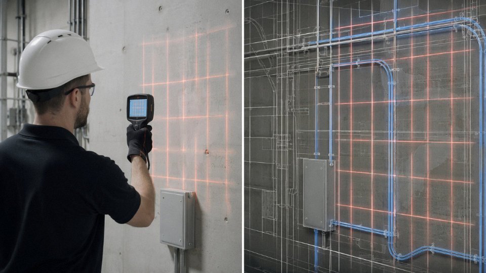
On projects designed after roughly 2015, IFC-format BIM models often contain dedicated cable tray, conduit, and containment layers that can be exported separately. Several field tools — including tablet-based apps compatible with Autodesk BIM 360 and Trimble Connect — can overlay those conduit layers onto a live camera view using the building’s structural reference points for registration. In practice, this augmented reality guidance is genuinely useful in congested ceiling voids or plant rooms where paper drawings become disorienting fast.
The caveat: BIM “design” models and BIM “as-built” models are not the same thing, and on many projects they diverge considerably.
Between 15% and 40% of installed cable routes deviate from original design drawings due to site modificationsTrue
Multiple utility mapping studies and post-installation surveys in commercial construction have documented this deviation range, which is driven by clashes with structure, late design changes, and field routing decisions made during installation without formal drawing updates.
That figure should make any contractor uncomfortable about relying on drawings alone. Physical scanning is non-negotiable even when you have good documentation.
Cross-Referencing Documents With Physical Reality: A Four-Step Protocol
A systematic approach looks like this:
Step 1 — Document review. Mark all known cable routes and circuits on a site plan. Note deviation zones and any circuits with unknown routing.
Step 2 — NCV scan. Walk the marked routes with a non-contact voltage detector to confirm which circuits are live and roughly where the field boundary sits. AC voltage detectors respond to electric fields at roughly 10–50 mm through standard drywall, depending on cable load and detector sensitivity — a useful first-pass confirmation.
Step 3 — CAT scan. Use a professional cable avoidance tool at 50/60 Hz to refine routing to ±20 mm or better in standard plasterboard. Mark deviations from the drawing directly on the wall or floor with removable marking tape.
Step 4 — Pilot hole. Before any core drill or chase cut, drill a small-diameter pilot hole — typically 6–8 mm — at the intended penetration point, angled to intercept the void before the cable zone. Visual inspection with a borescope takes about two minutes and has prevented more cable strikes than any amount of scanning confidence.
The protocol is not optional if the consequence of a strike is significant. In a live commercial kitchen, an office server room, or a manufacturing cell with 24/7 uptime requirements, skipping step four because the first three looked clean is exactly the kind of overconfidence that produces expensive failures.
Step-by-Step Safe Scanning Protocol for Five Common Wall and Floor Scenarios
No single method works everywhere. The five scenarios below cover the construction contexts you are most likely to face, and each one demands a slightly different tool combination and sweep discipline. Work through the relevant scenario before you pick up a drill.
Scenario 1 — Domestic Drywall Partition
Start with a plug-in circuit tracer or an NCV pen to confirm which circuits are live in the area. Then run the stud finder in metal-detection mode in horizontal passes at 300 mm, 900 mm, and 1,500 mm above floor level — the heights where electricians typically route cables between sockets and ceiling roses. Mark every response with low-tack tape, not pen, because you will often get ghost readings on the first pass and need to erase.
Once you have a consistent hit across two or three passes, treat the marked centre line as the cable’s nominal position and observe a minimum 50 mm clearance on both sides before drilling. In standard plasterboard this is conservative enough to account for the ±20 mm positional uncertainty a CAT tool carries in ideal conditions — and drywall is rarely ideal, especially if someone has added a skim coat or double-boarded for sound insulation.
Scenario 2 — Solid Brick or Block Wall
Plaster depth here typically runs 12–50 mm, which eats directly into your detection depth budget. A pen-type NCV detector may not respond reliably to a cable buried under 40 mm of dense sand-cement render, even with the circuit fully loaded.
Set a CAT instrument to sensitivity level 3 or 4 and sweep slowly — 150 mm per second or less. Mark the response envelope rather than just the peak. Before coring for a new service penetration, drill a single 6 mm pilot hole at the proposed centre to insert a borescope or a rigid wire probe. That five-minute check has saved more than a few coring contractors from a nasty surprise. If the borescope shows conduit or a cable sheath, abandon that location entirely.
Scenario 3 — Reinforced Concrete Floor or Ceiling Slab
GPR is not optional here. Map the rebar grid first — typically 150–200 mm centres in a two-way arrangement — and mark it on the slab surface with a chalk grid. Once rebar is plotted, re-scan specifically looking for anomalies that do not conform to the regular grid pattern: those outliers are usually conduits or embedded cables.
Set the depth stop on your rotary hammer to 20 mm shallower than the slab’s structural zone. Use a slow, consistent drilling speed and stop every 30 seconds to clear dust and re-check depth. Anti-vibration technique matters here: a hammer bouncing on aggregate can walk 10–15 mm off your marked centre.
Scenario 4 — Steel-Framed Commercial Partition
Steel studs generate constant false positives on any detector that reads ferromagnetic metal. The reliable method is to inject a signal generator at the distribution board onto the specific circuit you are concerned about, then sweep with the CAT receiver set to that signal frequency. The framing reads as a uniform background; the cable shows as a distinct anomaly superimposed on it. Takes an extra 20–30 minutes but eliminates the guesswork.
Scenario 5 — Outdoor Buried Cable in Soft Ground
Run a CAT/genny combination at 33 kHz and walk the line in overlapping passes 500 mm apart. Cross-check detected depth against any utility record depth markers — these are often unreliable after ground settlement or previous excavations, so treat them as a starting point only. Hand-dig trial holes within 500 mm either side of the detected centre line. Never use a mattock or powered auger directly over a suspected cable route.
Combining a signal generator with a CAT receiver at 33 kHz significantly improves cable discrimination accuracy in areas with metallic infrastructure compared to passive 50/60 Hz detection alone.True
Active signal injection gives the receiver a specific frequency to lock onto, reducing interference from background electromagnetic noise and structural metal, which is well established in utility location practice.
Universal Post-Scan Checklist
Before the job is signed off:
- Photograph every marked cable position with a tape measure in frame for scale
- Produce a dimensioned sketch referenced to fixed structural features — door frames, window reveals, floor level — not to furniture
- Log the tools used, sensitivity settings, and operator name; this matters for any future insurance or liability discussion
- Submit updated cable routing data to the building’s as-built drawing set or BIM model
That last step is the one most site teams skip, and it is exactly why the next trade through the wall is starting from scratch again.
How Cable Design and Installation Standards Affect Long-Term Detectability: Insights from a Cable Manufacturer
Most of the detection difficulty people encounter years after a building is finished comes down to decisions made at procurement and installation — not the limits of the scanning equipment. That’s a perspective you only really get from the manufacturing side.
Conduit and Trunking vs. Direct Burial in Walls
Cables pulled through PVC or steel conduit can be traced, re-identified, and often re-pulled without opening walls at all. Directly embedded cables — poured into screed or plastered over — give you no such option. The difference in future maintenance cost is enormous, and it almost never gets priced into the original installation budget.
Specifying conduit also means your cable route stays mechanically defined. A magnetic or CAT tool following a conduit gets a consistent, linear signal with predictable geometry. A direct-buried cable that has sagged, shifted during concrete pour, or been nudged by another trade runs at an irregular depth and angle. Locating it later is genuinely harder. If you’re writing procurement specs for a new build or major fit-out, mandating conduit in any wall or floor that might be modified within the building’s service life is one of the better maintainability decisions you can make.
Route Marking Tape and Tracer Wire — Often Skipped, Consistently Regretted
Properly installed cable route marking tape, placed roughly 300 mm above the cable during burial, gives the first locator before any electronic tool comes out. It’s cheap. It works. And in practice, probably half the direct-buried runs I’ve seen excavated in renovation work had no tape at all — or the tape was laid at inconsistent depth because it was treated as an afterthought rather than a specified installation step.
Tracer wire (a continuous metallic conductor running alongside a non-metallic cable) solves the signal problem for cables that produce weak electromagnetic signatures. Low-load circuits that aren’t energized at the time of scanning, or cables in plastic conduit with no ferrous content, can be nearly invisible to a standard CAT tool. A tracer wire changes that entirely — it gives the detector something to find regardless of load state.
XLPE vs. PVC Insulation and What It Changes for Detection
XLPE insulation's lower dielectric constant compared to PVC causes a marginally stronger electric field at the cable surface, making XLPE-insulated cables fractionally easier for NCV detectors to sense at equal depth.True
XLPE has a dielectric constant of roughly 2.3 versus PVC at 3.0–8.0 depending on plasticizer content; a lower dielectric constant means less attenuation of the electric field radiating outward from the conductor, which is the field an NCV detector responds to.
The practical difference is minor — don’t make insulation type your primary detection variable — but it’s worth knowing when you’re chasing a weak signal near the edge of a detector’s rated range.
Steel Wire Armoring: Strong Metal Signal, Screened Electric Field
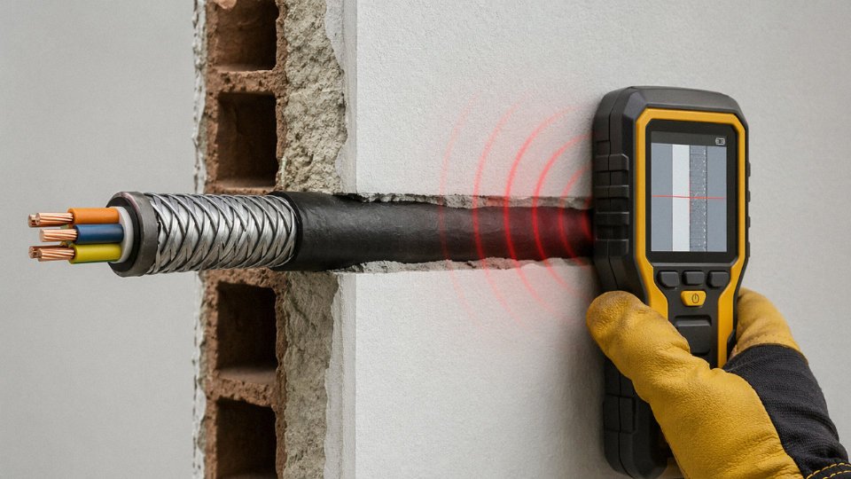
SWA and AWA cables are a specific case worth understanding. The metallic armor gives magnetic detectors an excellent ferromagnetic return — clean, strong, easy to trace. But that same armor acts as a partial Faraday cage around the inner conductors. An NCV detector relying on the electric field of the live conductors will get a weaker or absent response from an armored cable compared to an unarmored one at the same depth. If your wall scan is returning nothing on a voltage detector but you know a circuit is there, switching to a magnetic mode or a full CAT instrument is the right move.
Color Coding, Labeling, and Why Documentation Reduces Scanning Ambiguity
IEC 60446, BS 7671, and the NEC each define conductor color schemes for a reason: consistent identification reduces the risk of misidentifying a live conductor during maintenance. When cable color coding is paired with route documentation — actual as-built drawings, not the theoretical design drawings that frequently diverge from what was installed — the scanning task shifts from “find the cable” to “confirm the cable is where the drawing says.” That’s a fundamentally safer starting point.
Inconsistent color coding, which still appears in older installations or in regions where standards enforcement is loose, forces more reliance on electronic detection alone. That’s a higher-risk position.
Dimensional Consistency and Radar Reflection
From a manufacturing standpoint, dimensional accuracy matters for GPR-based wall scanning more than most people realize. GPR identifies buried objects partly by the consistency of the reflection — a cable with uniform outer diameter and concentrically centered conductors produces a clean hyperbolic reflection signature in GPR data. A cable with off-center conductors, irregular jacket thickness, or inconsistent armor lay produces a noisier return that’s harder to distinguish from rebar, conduit, or structural voids.
Dimensional tolerances of ±0.1 mm on cable outer diameter, achievable with modern extrusion control, produce noticeably more consistent GPR reflection signatures than cables with looser tolerances.True
GPR signal interpretation depends on dielectric contrast and geometric regularity; tighter dimensional tolerance means more predictable dielectric boundary geometry and a cleaner reflection hyperbola in processed GPR data.
Jinda’s production lines run spark testing at 6–15 kV (voltage depends on insulation thickness and voltage class) and conductor resistance verification per IEC 60228 as standard — not because detection performance is the primary driver, but because dimensional and electrical consistency is the baseline of a cable that performs predictably in service and in post-installation scanning alike. Cheap cable with poor dimensional control is a procurement decision that tends to cost more in maintenance than it saved at purchase.
Regulatory Requirements, Safety Standards, and Liability Considerations for Cable Detection Work
Most people scanning for cables before drilling are thinking about the cable. They should also be thinking about what happens legally if they get it wrong.
IEC 60364 and the International Baseline
IEC 60364 — Low Voltage Electrical Installations — is the reference framework that underpins national electrical codes across most of Europe, Asia, and large parts of the Middle East. Part 6 covers verification and inspection, and the underlying philosophy is clear: before any penetration work inside an electrical zone, the responsible party must be able to demonstrate that services have been identified and, where practicable, isolated or de-energized. “Where practicable” is doing a lot of work in that sentence. In practice, on occupied commercial premises, full de-energization before every drill hole is not always feasible — which is exactly why documented scanning becomes the compensating control. If a contractor cannot produce scan records showing due diligence, they cannot demonstrate compliance with the verification requirements, and that matters in any post-incident investigation.
UK Obligations: BS 7671, GS38, and the Health and Safety at Work Act
In the UK, the 18th Edition of the IET Wiring Regulations (BS 7671:2018, amended 2022) sets the technical standard. Regulation 522.6 specifically addresses cables concealed in walls, requiring that cables either follow prescribed safe zones or be mechanically protected — but critically, it also means the installer was supposed to leave a record of routing. If no record exists, the next contractor working on that wall is operating blind, and the obligation to survey before penetration shifts onto them.
HSE Guidance Note GS38 deals with test equipment and safe working near electrical systems. It is not just a recommendation document — the Health and Safety at Work Act 1974 creates a legal duty of care to employees and others who might be affected by work activity. Striking a live cable is a foreseeable harm. Failing to use available detection methods before drilling is very hard to defend as reasonable precaution under Section 2 or Section 3 of that Act.
In the UK, failing to detect and avoid a live concealed cable before drilling can constitute a criminal offense under the Health and Safety at Work Act 1974, not merely a civil liability.True
The Health and Safety at Work Act 1974 (Sections 2 and 3) imposes criminal liability on employers and self-employed persons who fail to take reasonably practicable steps to prevent foreseeable harm. Striking a live cable due to inadequate pre-work surveying has resulted in prosecutions by the HSE.
North America: NEC, OSHA Subpart K, and 811
NFPA 70 (the National Electrical Code) governs installation practice but does not directly mandate detection before drilling. The liability framework comes from OSHA 29 CFR 1926 Subpart K, which covers electrical safety in construction and requires that workers be protected from unrecognized electrical hazards — including concealed live conductors in walls and floors. “Unrecognized” is the operative word: if a hazard was identifiable with standard equipment and the employer did not use that equipment, Subpart K exposure is significant.
For outdoor buried utilities, every US state participates in the 811 call-before-you-dig system. Timelines vary — most states require 48 to 72 hours’ notice before excavation, though some allow shorter windows for emergency work. 811 covers utility-owned infrastructure; privately owned buried cables on a campus or industrial site are the owner’s responsibility to locate, which catches facility managers off guard more often than it should.
European Variations: EN 50110-1 and Fire-Rated Wall Penetrations
EN 50110-1 governs the operation of electrical installations across EU member states and is more operationally prescriptive than IEC 60364. It requires that work on or near live parts be authorized by a responsible person with documented competence. Germany, France, and the Netherlands each layer national building regulations on top of this — particularly relevant for penetrations through fire-rated walls, where drilling without proper reinstatement of fire stopping (and without knowing what services you have disturbed) can compromise compartmentalization in ways that only become visible during a fire investigation.
Insurance and Criminal Liability After a Cable Strike
This is the part contractors sometimes skip reading until it affects them directly. An undocumented cable strike — meaning no pre-work scan records, no permit-to-work, no isolation verification — can void a contractor’s liability insurance outright. Most commercial liability policies contain a reasonable precaution clause, and failure to use available detection technology can be characterized as failure to take reasonable precaution. Beyond civil exposure, where a worker is injured or killed, corporate manslaughter statutes in the UK, Australia, and several EU jurisdictions allow prosecution of the organization itself, not just an individual employee.
The practical consequence: scan records, calibration certificates for your equipment, and a signed permit-to-work are not bureaucratic overhead. They are your defense documentation.
Competency Requirements Vary Widely by Jurisdiction
In the UK, City & Guilds 2395 (Inspection, Testing, and Certification of Electrical Installations) is the recognized qualification for the person authorizing work near live electrical systems in commercial buildings. Not every person operating a cable detector needs this qualification, but the person signing off on the scan results and authorizing penetration typically should have it, or equivalent demonstrated competence.
Australia is more prescriptive. AS/NZS 3000 (the Wiring Rules) and state-level electrical licensing legislation in most jurisdictions require a licensed electrician to authorize, and often supervise, penetration work in proximity to live cables. New South Wales, Victoria, and Queensland all have licensing frameworks where unlicensed cable strike work carries fines and potential license implications for the principal contractor.
The honest operational summary: the required standard of care is higher than most people assume, and it varies enough between jurisdictions that assuming your home-market habits transfer automatically to an international project is a genuine risk.
Frequently Asked Questions About Detecting Power Cables in Walls
Can a cheap stud finder reliably detect live cables, or do I need a dedicated cable detector?
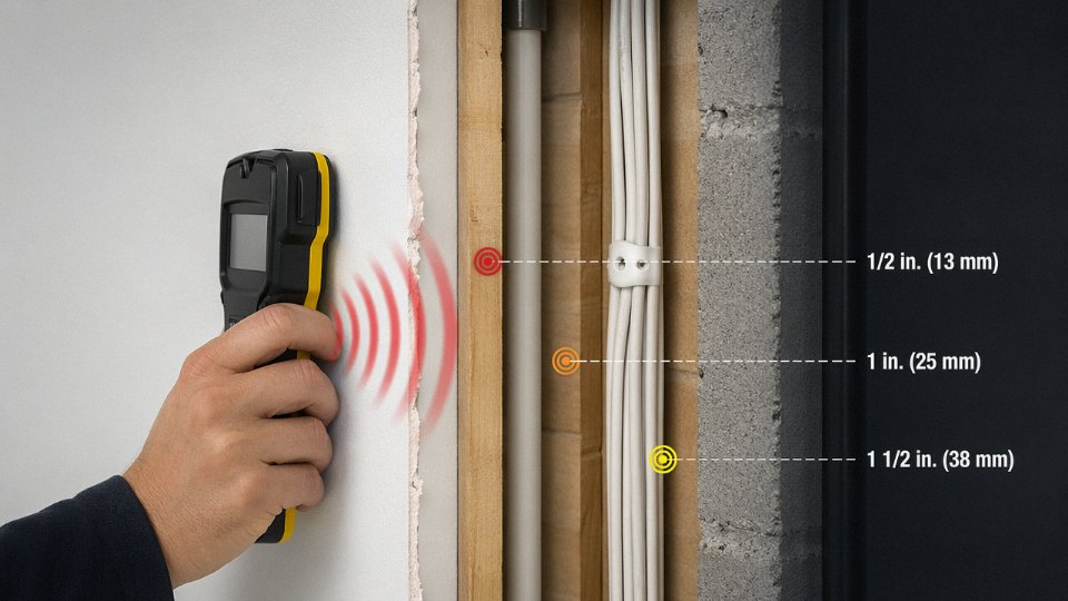
Budget stud finders — the kind that cost under $30 and are sold as “multi-function” — can pick up a heavily loaded 120V or 230V cable in shallow plasterboard if you are lucky. Reliable is a different word. Their NCV sensitivity is typically tuned coarse, and they produce both false positives near earthed metal and false negatives on lightly loaded circuits. For a single DIY shelf bracket into a known internal partition wall, an NCV-mode stud finder combined with slow, overlapping passes is a reasonable first step. For anything structural, commercial, or in a wall you cannot fully characterize — old concrete, a wall that has been skimmed multiple times, any surface near a consumer unit — you want a dedicated cable avoidance tool (CAT). The sensitivity difference is not marginal. It is the difference between a device designed to detect electrical fields and one that happens to have a detection mode bolted on.
How deep in a wall can a standard NCV detector find a cable?
Practical reliable range sits between 10 mm and roughly 50 mm through standard plasterboard or a single coat of plaster. Beyond 50 mm the signal usually falls below the alarm threshold unless the cable is running close to full load — think a ring main supplying several high-draw appliances simultaneously. Cable gauge matters too; a 4 mm² circuit radiates a stronger field than a 1 mm² lighting spur under equivalent load. In thick masonry or walls with a dense skim coat, never assume the detector’s silence means all-clear. It may simply mean the cable is too deep for the tool you are using.
Standard NCV pen detectors cannot reliably detect cables buried deeper than 50 mm in masonry wallsTrue
NCV detectors respond to the electric field radiated by a live conductor; field strength follows an inverse-square relationship with distance, and at depths beyond roughly 50 mm in dense material, signal strength typically drops below the detection threshold of consumer-grade devices.
Will a cable detector find a cable that is switched off or carrying no load?
An NCV detector will not — it senses an alternating electric field, and a de-energized cable produces none. A metal-detection mode on a stud finder may locate armored cable or steel conduit because it is sensing ferrous mass, not voltage. For an unarmored de-energized cable, your only solid options are a signal generator paired with a CAT receiver, or ground-penetrating radar. This is a genuine gap that catches people out during renovation work, where a previous owner may have left isolated circuits in the wall.
Is it safe to drill a small pilot hole to check for cables?
Only after scanning. Use a 3 mm wood bit, set a depth stop or wrap tape at 20–25 mm, and do not push through in one motion — drill a few mm, withdraw, check the tip. Once you are through the plaster face, stop. A borescope or even a phone camera with a flexible attachment will let you look into the cavity before committing to the full hole diameter. This approach is reasonable on internal stud partitions where the cable void is relatively predictable. On a solid masonry wall where a cable could sit at any depth, the pilot approach is much riskier and a CAT scan first is non-negotiable.
How do I find cables in a wall with no circuit drawings at all?
Start at the consumer unit. Label every breaker by switching circuits off one at a time while a colleague checks which outlets and fittings lose power — tedious but accurate. Then use a plug-in socket tracer to inject a signal and follow it with the CAT receiver, working from the consumer unit outward along the suspected route. Draw what you find by hand onto a rough sketch of the floor plan. It does not need to be pretty; it needs to exist so the next person is not starting from zero again.
Can thermal imaging replace a cable detector?
No. Thermal cameras only show loaded cables that have had enough time to warm their surrounding material — typically 30 minutes to an hour of moderate load under normal ambient conditions. They give you no reliable depth information at all, and they will miss any circuit that is energized but lightly loaded. Where thermal imaging genuinely earns its place is confirming that a route you have already detected with a CAT tool is live, and flagging insulation that is running hotter than expected — which is worth knowing for its own reasons.
What is the minimum safe drilling distance from a detected cable centerline?
Most practical guidance and code commentary lands at 50 mm clear distance from the detected centerline for a standard partition wall. In a load-bearing wall or anywhere near a structural element, 75 mm is a more defensible margin and you should be consulting a structural engineer about the hole itself anyway. Remember that detection accuracy for a professional CAT tool in standard plasterboard is roughly ±20 mm under good conditions — so that 50 mm clearance accounts for both the tool’s positional uncertainty and normal cable movement during installation.
Do IEC or BS standards specify cable routing to help future detection?
Yes, and this is worth understanding at procurement and installation stage, not just during renovation. IEC 60364-5-52 and BS 7671 both define prescribed cable zones — essentially vertical and horizontal corridors running from outlets, switches, and junction boxes. Cables must run within these zones, which means a future scanner who knows the standard can make educated predictions about where a cable is likely to be before the first sweep. Whether a given installation actually follows those routes is a separate question; in practice, many older installations and some rushed commercial fit-outs do not. But on any project where Jinda cables are specified and installed to current standards, following defined routing zones from day one costs nothing extra and materially reduces future detection difficulty and liability exposure.