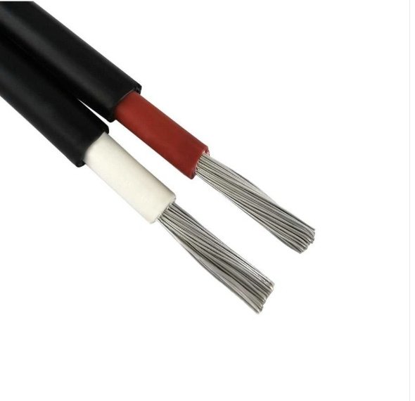
Grabbing the wrong wire from a mixed stockroom bin — or trusting a label someone scrawled on a conduit years ago — is the kind of mistake that shows up later as a nuisance breaker trip, a failed inspection, or in worse cases, insulation breakdown and a fire investigation. Wire identification looks like a housekeeping task. It isn’t. Misidentified conductors drive real costs: overloaded circuits, voided warranties on downstream equipment, rejected UL or CE audits, and emergency rewiring that costs five to ten times what a proper labeling system would have cost on day one.
You identify electrical wire type by reading the printing on the jacket or insulation (which states the conductor size, insulation class, voltage rating, and standard such as NEC or IEC), checking the conductor construction (solid vs. stranded and the strand count), measuring the cross-section with a caliper or wire gauge tool, and noting the jacket color — cross-referencing these against AWG tables or IEC 60228 conductor classes.
What makes this genuinely tricky is that wire from different eras, different sourcing regions, or different plant expansions rarely follows one standard. You might have AWG 12 THHN in the same panel as 2.5 mm² IEC-rated cable, both doing roughly the same job, both looking nearly identical on the spool — but they aren’t interchangeable, and the insulation temperature ratings, ampacity derating rules, and termination requirements differ in ways that matter when you’re at 80% load on a hot summer shift.
Reading the Print Line: Decoding Every Code Stamped on a Cable Jacket
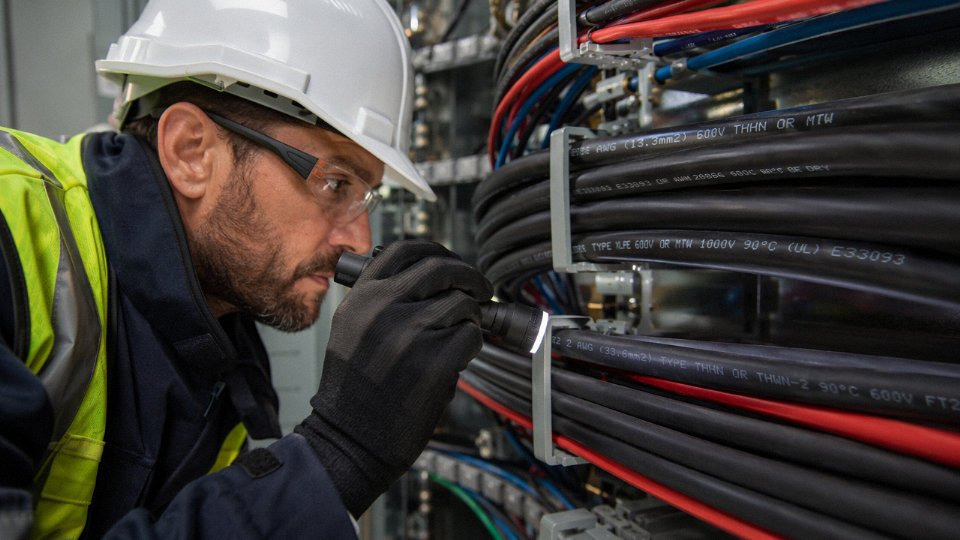
The fastest way to identify a cable is standing right in front of you — it’s the alphanumeric string printed along the jacket every few inches. Most people glance at it and move on. That’s a mistake. A trained eye can pull conductor size, insulation chemistry, voltage rating, temperature limits, listing authority, and intended environment off that single line in about ten seconds. Here’s how to read every field.
The North American Print Line Sequence
On UL-listed wire manufactured for the US and Canadian markets, the print line follows a fairly consistent order: manufacturer or brand name, trade name or product series, wire gauge (AWG), number of conductors, insulation type code, voltage rating, temperature rating, and finally the listing marks (UL, CSA, or both). A typical 12 AWG building wire might read something like: BRAND NAME / THHN / 12 AWG / 600V / 90°C / UL. Each field is load-bearing. Skip one and you may spec the wrong wire for a wet-location panel feed or a high-ambient motor connection.
The insulation type codes are where most confusion lives, so it’s worth breaking them down character by character.
T — thermoplastic insulation (the base material, usually PVC)
H — heat-resistant, rated to 75°C
HH — high heat, rated to 90°C
W — suitable for wet locations
N — nylon outer jacket (adds abrasion and chemical resistance)
-2 suffix — 90°C rating in wet environments specifically
So THHN is thermoplastic, 90°C dry, nylon-jacketed — the single most common building wire in North American commercial construction. THWN-2 adds wet-location approval at 90°C, which matters enormously if the conduit runs through a mechanical room that floods seasonally or an outdoor riser exposed to condensation. XHHW-2 swaps the thermoplastic for cross-linked polyethylene (XLPE), giving you 90°C wet with better long-term thermal stability — worth the small price premium on feeders that run near heat sources. USE-2 (Underground Service Entrance, -2 suffix) is rated for direct burial and 90°C wet; don’t confuse it with UF-B, which is a flat-sheathed cable with a different construction entirely. RHW uses rubber insulation — you still find it in older industrial plants, and the absence of a “2” suffix means it’s rated 75°C wet, not 90°C.
IEC and European Harmonized Codes
The European harmonized system works differently. A H prefix means the cable meets the CENELEC harmonized standard; a national code (like A for Austria, or no prefix for a manufacturer’s standard) means it’s national-only. Next comes the voltage class: 03 = 300/300V, 05 = 300/500V, 07 = 450/750V. Conductor material follows — blank means copper, A means aluminum. Insulation material: V = PVC, X = XLPE, R = rubber, S = silicone. The construction suffix at the end covers sheath and flexibility class.
H05VV-F is a flexible PVC-insulated, PVC-sheathed cord at 300/500V — your standard European appliance lead. H07RN-F is heavy-duty rubber-insulated, neoprene-sheathed, rated 450/750V — the one you want for portable equipment on a factory floor or outdoor temporary power. The -F suffix indicates flexible stranding (roughly IEC Class 5), which matters for anything that moves.
Chinese GB/T Marking Conventions
On project specifications sourced from Chinese manufacturers — including Jinda’s product range — the designations follow GB/T standards with a different logic. YJV means XLPE-insulated, PVC-sheathed power cable; VV is PVC-insulated and PVC-sheathed throughout. Prefix ZR (flame retardant) or NH (fire resistant, circuit integrity maintained under flame) gets prepended when the application demands it. A full designation like ZR-YJV-0.6/1kV tells you the cable is flame retardant, XLPE insulated, PVC sheathed, and rated for 0.6/1kV systems — the standard for most Chinese industrial distribution. NH-VV would be fire-resistant PVC cable, typically specified for emergency power circuits in high-rise buildings.
Chinese GB/T cable designations use the ZR prefix to indicate flame-retardant performance and NH to indicate fire-resistant (circuit-integrity) performance — these are distinct properties and the codes are not interchangeable.True
Under GB/T 19666 and related standards, ZR (阻燃, flame retardant) means the cable resists flame propagation but does not guarantee circuit continuity under fire. NH (耐火, fire resistant) means the cable maintains circuit function for a defined period under direct flame — a much stricter requirement used for emergency systems.
Cross-Reference Table: 12 Common Cable Codes
| Code | Insulation | Voltage Rating | Typical Application | Standard |
|---|---|---|---|---|
| THHN | PVC + nylon | 600V | Commercial building wiring, conduit | UL 83 |
| THWN-2 | PVC + nylon | 600V | Wet conduit, outdoor risers | UL 83 |
| XHHW-2 | XLPE | 600V | Feeders, high-ambient environments | UL 44 |
| USE-2 | XLPE or rubber | 600V | Direct burial, service entrance | UL 854 |
| RHW | Rubber | 600V | Older industrial, switchgear | UL 44 |
| NM-B | PVC (flat sheath) | 600V | Residential branch circuits | UL 719 |
| H05VV-F | PVC/PVC flexible | 300/500V | Appliance cords, light equipment | IEC 60227 |
| H07RN-F | Rubber/neoprene | 450/750V | Portable industrial, outdoor | IEC 60245 |
| H07V-U | PVC solid | 450/750V | Fixed building wiring (EU) | IEC 60227 |
| YJV | XLPE/PVC | 0.6/1kV typical | Chinese industrial power distribution | GB/T 12706 |
| ZR-YJV | XLPE/PVC (FR) | 0.6/1kV typical | Flame-retardant power cable | GB/T 19666 |
| NH-VV | PVC/PVC (FP) | 0.6/1kV typical | Emergency circuits, fire systems | GB/T 19666 |
When the Print Line Is Gone
Aged cables — particularly anything installed before the mid-1980s — often have worn, faded, or thermally degraded print lines. On cables that have run hot for years, the ink disappears entirely. Conduit fill and tight J-hooks accelerate abrasion. In those cases, you cannot rely on the jacket alone and need to move to physical inspection: jacket color conventions, conductor color coding, and where necessary, direct measurement of conductor cross-section. Those methods are covered in the sections that follow.
Don’t guess at an illegible print line. An undersized or wrong-rated wire identified incorrectly is how nuisance trips become arc faults.
Color Coding by Region and Application: What Each Conductor Color Actually Means
Color coding looks like a shortcut. In practice, it’s a starting point — and a dangerous one if you’re working across national borders or in a building that’s been rewired piecemeal over forty years.

North American NEC Conventions
Under NEC practice, black, red, and blue identify ungrounded (hot) conductors in single- and three-phase systems. White or gray is the grounded conductor — what most people call neutral. Green or bare copper is the equipment grounding conductor. That much is consistent.
What surprises a lot of engineers moving from residential to commercial work is that hot conductor colors beyond black are not standardized in the NEC the way neutral and ground are. You’ll find installations using orange, yellow, or even brown for the second and third phase legs, especially in older industrial plants. Some facilities adopt an internal color standard and document it in the panel schedule; others don’t. Never assume that because a conductor isn’t white or green it’s automatically a phase wire with a known voltage relationship to another conductor you’re holding.
IEC 60446 and the Post-2004 European Shift
Europe harmonized under IEC 60446 in 2004, and the result is now the baseline for most of the world outside North America. Brown is line (L), blue is neutral (N), and green-yellow stripe is protective earth (PE). Three-phase systems run brown, black, and gray for L1, L2, and L3.
The problem you’ll encounter on retrofit and expansion projects is pre-2004 UK wiring, which used red for live, black for neutral, and green (or green-yellow in later versions) for earth. That old UK red wiring is still live in countless commercial buildings — sometimes right next to a newer IEC-harmonized circuit someone added during a refurbishment. A black conductor in a pre-2004 UK installation is neutral. A black conductor in a post-2004 IEC installation is a live phase. Same color, opposite function. That’s the kind of thing that sends people to hospital.
Australian AS/NZS 3000 — The Reverse Neutral Problem
Australia uses red for the active conductor and green-yellow for earth — straightforward enough. The trap is neutral: it’s black under AS/NZS 3000. For any engineer trained in North American practice, black means hot. Wiring imported equipment or interfacing with Australian-built machinery without knowing this convention is genuinely dangerous, not just a compliance issue.
In Australia, the neutral conductor is black under AS/NZS 3000, which is the opposite of North American NEC convention where black indicates a hot conductor.True
AS/NZS 3000:2018 specifies black for the neutral (return) conductor in Australian fixed wiring, while NEC Article 200 reserves white or gray for the grounded (neutral) conductor and permits black as an ungrounded (hot) conductor.
Industrial Control and Machine Tool Wiring
NFPA 79 governs machine tool and industrial control wiring in North American facilities, and it runs a completely separate color logic from the NEC’s power wiring conventions. Orange identifies ungrounded control wiring — circuits that remain live even when the main disconnect is open, which matters enormously for lockout/tagout procedures. Yellow marks interlock circuits. Blue is DC positive; white covers DC negative and AC control neutral.
Walk into a complex automated cell and you’ll often see all four of these plus standard NEC power colors within the same enclosure. Mixing them up during a modification isn’t just an electrical code violation — it can defeat a safety interlock silently, with no immediate indication until a machine cycles unexpectedly.
Thermocouple and Instrumentation Cable
This one catches process plant engineers repeatedly. Type K thermocouple cable — chromel-alumel, the most common type in industrial temperature measurement — is yellow with a red negative lead under ANSI/ASTM E230. Under IEC 60584-3, the same Type K pair is green overall with a white negative. If you’re commissioning a skid built to IEC standards inside a plant that uses ANSI wiring conventions, you’re looking at two incompatible color schemes on what appears to be identical cable. Reversed thermocouple polarity doesn’t blow a fuse or trip a breaker; it just gives you a temperature reading that drifts in the wrong direction, which can go unnoticed until a process excursion happens.
Color Is a Screening Tool, Not a Verdict
Aged wiring loses color saturation — a green wire that’s been baking at 80°C for fifteen years can look brown under bad lighting. Field re-taping, non-compliant installations, and color-coded heat shrink applied by a previous contractor are all common. The color you see gets you oriented. It does not replace reading the jacket print line and doing a physical check with a meter.
Photograph everything before you disconnect anything, especially on international equipment retrofits. Note the country of manufacture, find the applicable national standard, and cross-reference both before you trust what the color is telling you. It takes two minutes and it’s saved more than a few retrofits from a very expensive fault.
Solid, Stranded, and Flexible: Identifying Wire Construction by Physical Inspection
Strip back the jacket on an unknown cable and the conductor itself tells you a great deal — if you know what to look for. Construction class determines where a wire can legally go, how it terminates, and whether it survives the mechanical environment it’s about to live in.
The Three Broad Classes (and What IEC 60228 Actually Says)
IEC 60228 defines conductor classes 1 through 6. Class 1 is solid — one single cylindrical conductor, no stranding at all. Class 2 is the stranded-but-stiff category most people think of as “standard building wire,” and it covers the majority of fixed installation cable worldwide. Classes 3 and 4 step up the strand count for better flexibility, while Classes 5 and 6 are the genuinely flexible conductors: fine wire counts, soft feel, designed for movement. In North America, the AWG system doesn’t map perfectly onto these classes by name, but the physical logic is identical.
Identifying Solid Wire in the Field
At a stripped end, solid wire looks like a single polished rod — perfectly circular, catches light evenly, no gaps between strands because there aren’t any. You’ll feel the stiffness immediately when you try to bend it; AWG 12 solid copper resists bending with noticeable force, AWG 10 even more so. Solid conductors dominate residential branch circuits (AWG 14 for 15 A circuits, AWG 12 for 20 A), conduit runs in commercial buildings, and any fixed wiring where the cable never moves after installation. The rigidity that makes it awkward to pull through a tight conduit bend is also what makes it dimensionally stable in a screw terminal — the wire doesn’t spring back or splay.
One practical note: pushing solid wire into a backstab connector repeatedly will cold-work the copper at the notch and eventually crack it. That failure mode is almost invisible until you have a loose connection causing arcing. Worth keeping in mind.
Reading Strand Count to Estimate Class
Count the individual wires at a stripped end. Seven strands arranged as a central wire surrounded by six is the classic Class 2 geometry — this is your standard NM-B, THHN, or similar fixed wiring product. Nineteen strands suggests Class 3 or Class 4, noticeably more pliable. When you get to 49 or more very fine strands — so fine they’re almost hair-like — you’re looking at Class 5 flexible conductor, used in cables like H05VV-F or flexible cords meant for appliances and light portability.
This matters enormously at termination points. A 7-strand Class 2 conductor seats cleanly under a bolt lug. A 49-strand Class 5 conductor pushed bare into the same lug will have fine wires escaping the clamping zone, increasing resistance and creating a potential hot spot over time. Class 5 and 6 conductors need ferrules, compression terminals, or ring lugs crimped with a ratcheting tool — not optional on equipment rated for it.
Fine-stranded Class 5 conductors require ferrules or compression terminations when connected to standard screw or bolt lugsTrue
Fine strands can escape the clamping area of a screw lug, increasing contact resistance and creating localized heating. IEC 60999-1 and most equipment manufacturers specify ferrule termination for flexible conductors in this class.
Concentric, Compressed, and Compact Stranding
These three variants are easy to confuse because they’re all “stranded,” but the cross-section geometry differs and it has real consequences for conduit fill calculations.
Concentric stranding is the textbook arrangement: layers of wires wound in alternating directions, perfectly round cross-section, air gaps between strands. Compressed stranding uses the same layered geometry but the layers are slightly rolled together, reducing the OD by roughly 3–5% compared to concentric. Compact stranding goes further — the stranded conductor is drawn through a die after stranding, closing most of the interstitial voids and producing a conductor closer in diameter to solid, often 10–15% smaller OD than concentric stranded equivalents at the same cross-sectional area.
On a large commercial project where you’re pulling multiple conductors through a common conduit, compact stranded XLPE cables can make the difference between fitting a 4-inch conduit or having to upsize to a 5-inch — a meaningful cost and labor difference. Manufacturers producing cables to IEC 60228 Class 2 compact stranding, including products from Jinda’s medium-voltage XLPE lines, document the compact OD explicitly in their datasheets precisely because engineers need it for fill calculations.
Rope-Lay and Bunch-Stranded: The Welding Cable Feel
Pick up a welding cable or a SOOW portable cord and the difference is immediate — it feels almost fabric-like, bends in any direction with minimal force, and the individual strand wires are often so fine you can barely see them without magnification. Rope-lay construction groups fine strands into small bundles (“ropes”), then lays those bundles together. Bunch stranding simply twists all the fine wires together without geometric order. Neither is designed for fixed installation; both are built for repeated flexing, dragging across floors, and coiling.
The H07RN-F designation (common in Europe for rubber-jacketed flexible cords) and SOOW (North America, oil-resistant thermoplastic) are your signpost markings for these constructions. If you find a cable with these designations running as fixed building wiring inside conduit, that’s a code violation in most jurisdictions — flexible cords aren’t rated for that application regardless of how tempting it is to use what’s on hand.
Specialty Constructions Worth Recognizing
Concentric neutral cables, used for underground residential distribution (URD), have a stranded center conductor surrounded by insulation, then by copper neutral wires helically wound around the outside. Peel back the outer jacket — if there’s a layer of individual copper wires spiraling around the insulation, you have concentric neutral cable, not a shielded instrumentation cable.
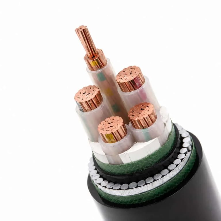
Drain-wire shielded cable for instrumentation looks superficially similar: a foil or braided shield, but with a single bare or tinned copper wire lying alongside the conductors inside the shield — the drain wire. Its purpose is termination convenience for the shield. Sector-shaped conductors appear in multi-core power cables, typically 3- or 4-core designs where each conductor is shaped like a pie wedge rather than a circle, reducing the overall cable OD. You’ll only see the sector shape clearly if you cut the cable cleanly across its cross-section; a slightly angled cut distorts the geometry.
Field Tools That Actually Help
A wire stripper with gauge markings on the jaw gets you a rough AWG estimate without needing anything else. For strand counting, a jeweler’s loupe in the 10× range or simply your phone’s macro camera mode works well — zoom in on the stripped end and count. A digital caliper measuring the overall conductor OD, then cross-referenced against the manufacturer’s datasheet, will confirm the exact cross-sectional area more reliably than strand-counting alone, especially on compact or compressed stranding where the geometry isn’t standard.
Copper vs. Aluminum vs. Specialty Alloys: Identifying Conductor Material Without a Lab
Getting this wrong is not a minor paperwork issue. Aluminum and copper terminate differently, expand and contract at different rates, and require entirely different hardware torque specifications. Connecting an aluminum conductor to a copper-rated terminal — no lug, no antioxidant compound, wrong torque — is one of the most reliably documented causes of connection-point fires in residential and light commercial wiring. So here is how you tell them apart on the floor, without a spectrometer.
Visual Color: The First and Fastest Check
Freshly stripped copper is a warm reddish-orange, close to the color of a new penny. If the conductor has been exposed to air for more than a few minutes it starts oxidizing toward brown, and left long enough it goes nearly black. That dark surface is copper oxide — conductive enough that it rarely causes immediate problems, but the color shift confuses people who expect copper to look bright.
Aluminum is silver-white when freshly cut, roughly the color of the inside of a soda can. Within seconds of exposure it develops a thin, dull gray-white aluminum oxide film. That oxide layer is electrically resistant, which is exactly why it matters at terminations. The visual difference between the two materials when freshly scratched is unambiguous — you should not need a second opinion.
Weight: Harder to Fake Than Color
Pick up a meter of cable. Aluminum runs about one-third the density of copper — 2.7 g/cm³ versus 8.96 g/cm³. In practical terms, a 95 mm² aluminum conductor cable weighs roughly 0.26 kg/m, while the copper equivalent is closer to 0.85 kg/m. That difference is immediately obvious when you’re pulling cable off a reel. If a 35 mm² cable feels surprisingly light for its diameter, start suspecting aluminum before you even strip it.
Bend and Flex Behavior
Copper is forgiving. You can work it back and forth repeatedly and it stays ductile. Aluminum work-hardens. Bend a large-gauge aluminum conductor at the same spot five or six times and it will crack — not gradually weaken, actually crack. For smaller gauges the failure comes even faster. On a job site, if a conductor snaps or develops visible surface cracking after modest handling, aluminum is the probable explanation.
The Magnet Test — and What It Actually Proves
Both copper and aluminum are non-magnetic. A magnet will not stick to either. If your conductor does attract a magnet, you’re looking at steel — most likely steel-core strand from an ACSR overhead conductor, or copper-clad steel used in messenger wire or some communication cables. The magnet test rules steel in, but it cannot distinguish copper from aluminum. Use it as a screening step only.
The Scratch Test: Most Reliable Field Method
Take a pocket knife and lightly scratch the conductor surface, just enough to break through the oxide layer. Bright orange-red underneath means copper. Bright silver-white means aluminum. This takes three seconds and is more reliable than color alone, especially on aged, dirty, or heavily oxidized conductors.
Aluminum Alloy (AA-8000 Series): Looks the Same, Terminates Differently
AA-8000 series aluminum alloy conductors, specified under ASTM B800, are visually identical to standard 1350-series aluminum. You cannot tell them apart by eye, scratch test, or weight. The only reliable identification is the cable print line — look for markings like AA-8000 or Al Alloy. Why it matters: AA-8000 alloy has better creep resistance and improved termination performance, but listed connectors and torque values are specific to the alloy designation. Using a connector listed only for 1350 aluminum on an AA-8000 conductor, or applying the wrong torque, voids the listing and creates a latent failure point.
AA-8000 series aluminum alloy conductors are visually indistinguishable from standard 1350 aluminum and can only be reliably identified by the cable jacket print line marking.True
Both alloys share the same silver-white appearance and similar density. ASTM B800 governs the AA-8000 series composition, and conductor identification must come from the manufacturer's jacket markings or certified test documentation — not physical inspection alone.
Copper-Clad Aluminum (CCA): The Import Problem
CCA has become increasingly common in lower-cost cable imported into markets with less rigorous incoming inspection. The outer conductor layer is copper; the core is aluminum. At a clean cross-section cut you can see the difference clearly — a bright orange ring around a silver-white core. The boundary is usually visible with good lighting and a hand lens, though on small gauges it takes a sharp, flat cut to see it.
CCA conductivity runs around 61% of solid copper on an IACS basis, versus 100% for pure copper. That means a CCA conductor needs a larger cross-section to carry the same current safely. Using it as a direct substitute for copper at the same gauge creates a chronic overheating condition that may not trip a breaker until something has already been burning for a while. The NEC and several other national codes restrict or outright prohibit CCA in building wiring branch circuits. If you’re sourcing cable internationally in volume, incoming inspection should include cross-section verification — a $15 wire stripper and ten seconds per sample is enough to catch it.
| Material | Freshly Cut Color | Magnet Reaction | Weight (95 mm², ~1 m) | Key Risk at Termination |
|---|---|---|---|---|
| Copper | Orange-red | None | ~0.85 kg | Wrong lug alloy rating |
| Aluminum (1350) | Silver-white | None | ~0.26 kg | Creep, oxide, wrong torque |
| Aluminum Alloy (AA-8000) | Silver-white | None | ~0.26 kg | Wrong listed connector |
| Copper-Clad Aluminum | Orange ring / silver core | None | Intermediate | Under-rated ampacity |
| Steel-core (ACSR) | Silver-gray | Attracted | Heavier | Wrong termination hardware entirely |
Weight figures depend on stranding class and jacket thickness; treat these as field estimates, not engineering design values.
Insulation and Jacket Material Identification: PVC, XLPE, Rubber, LSZH, and Beyond
Knowing the conductor material and gauge gets you halfway there. The insulation compound completes the picture — it determines voltage rating, temperature ceiling, chemical resistance, and how the cable behaves in a fire. Mixing up PVC and LSZH in a tunnel installation, or mistaking EPR for standard PVC in a mining application, isn’t a paperwork problem. It’s a failure mode waiting to happen.
PVC — The Default You’ll Encounter Most Often
Polyvinyl chloride covers probably 60–70% of the building wire you’ll ever handle, depending on region and application. It has a smooth, slightly glossy surface and bends easily at room temperature without cracking. Cut through a PVC jacket with a utility knife and you’ll catch a faint chemical smell — mild but distinct, nothing like rubber or polyethylene. Standard PVC insulation is rated 70°C; heat-stabilized grades reach 90°C and are increasingly common in modern installations. On the print line, IEC-standard cables stamp a V for PVC, while North American cables use T (thermoplastic) or TW for wet-location rated variants.
One practical caution: PVC stiffens noticeably in cold weather, sometimes below 0°C. On a winter job site pulling cable through conduit, flexible-at-room-temperature PVC can become brittle enough to crack at the bend radius. Worth knowing before you blame the installer.
XLPE — The Harder, Tougher Upgrade
Cross-linked polyethylene feels noticeably different from PVC. The surface is less glossy, slightly waxy to the touch, and the material has elastic memory — bend it sharply, release it, and it springs back toward its original shape rather than holding the kink. That’s the cross-linking at work. It also has no real smell when cut.
XLPE carries a 90°C continuous rating and withstands 250°C under short-circuit conditions, which is why it dominates medium-voltage power cable and any installation where thermal cycling is a serious concern. Chemical resistance is substantially better than PVC as well — relevant in petrochemical plants and water treatment facilities where the jacket might see oils, acids, or cleaning agents. IEC cables mark it X; North American designations include XLP or XHH. Jinda’s YJV and YJLV series both use XLPE insulation as standard.
EPR — When Flexibility at Low Temperature Is Non-Negotiable
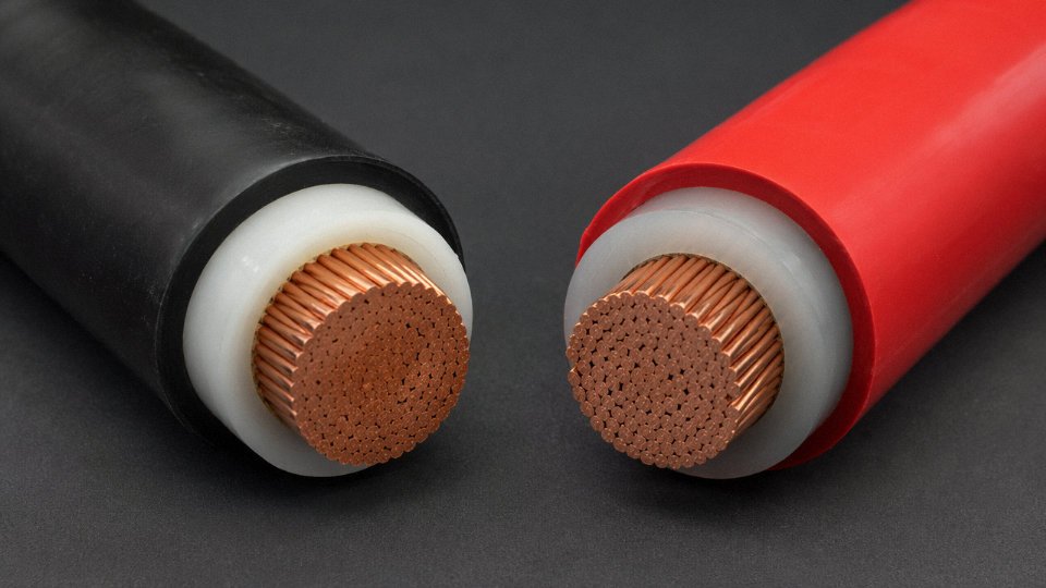
Ethylene propylene rubber has a matte, slightly tacky surface — almost like a firm rubber eraser — and stays flexible down to roughly -40°C. That’s why you find it in mining cables, shipboard wiring, and portable industrial equipment that gets dragged around in cold environments. The IEC print code is R; North American equivalents often appear as EP. EPR doesn’t have the same chemical resistance as XLPE against hydrocarbon oils, so confirm the specific compound grade before specifying it in refinery applications.
LSZH/LSOH — Looks Like PVC, Behaves Completely Differently in a Fire
Low smoke zero halogen insulation is the one material where visual inspection alone will get you into trouble. The surface looks similar to PVC — slightly matte rather than glossy, but not dramatically different unless you’re comparing samples side by side. The identification method that actually works is the burn test.
Burning PVC insulation releases hydrogen chloride (HCl) gas and dense black smoke, while LSZH compounds produce minimal, primarily white smoke and no halogen acid gases.True
This is well-documented combustion chemistry. PVC contains chlorine by composition; thermal decomposition releases HCl, which is both toxic and corrosive to electronics and metal infrastructure. LSZH compounds use halogen-free base polymers — typically polyolefin blends — to eliminate this. This difference underpins fire classification standards including IEC 60332 and EN 50575.
Take a small cut sample — maybe 25–30 mm — outdoors or in a genuinely well-ventilated space, away from the cable run, never on anything live. Hold a flame to the cut end for a few seconds, then remove it. LSZH burns with minimal smoke and self-extinguishes quickly. Burning PVC produces thick, acrid black smoke and a sharp, unmistakable HCl smell. If you see blue-green flame color, you almost certainly have a chlorinated compound — standard PVC or CPVC. Char residue on LSZH tends to be dry and powdery; PVC leaves a stickier, darker residue.
LSZH is mandatory in tunnels, rail rolling stock, marine vessel interiors, and data centers under IEC 60332 and EN 50575 C classifications. Installing standard PVC in these locations isn’t just a specification deviation — in some jurisdictions it fails the commissioning inspection outright.
Silicone, Neoprene, and CPE — The Specialty Outer Layer Materials
Silicone rubber is visually distinctive: milky white or translucent, exceptionally soft, almost gel-like in feel. It operates from roughly -60°C to +180°C continuously, which is why you find it on furnace wiring, inside industrial ovens, and in some medical equipment. The trade-off is mechanical fragility — silicone tears relatively easily compared to XLPE or neoprene, and it should not be pulled through conduit with the same force you’d use on standard building wire.
Neoprene (polychloroprene) and CPE (chlorinated polyethylene) appear as black, matte outer jackets on heavy-duty flexible cords and mining cables. Neoprene has a characteristic rubbery resilience — compress it with your thumbnail and it pushes back firmly. The cord designations to look for are SO, SOW, or SJO in North American systems, or H07RN-F under the EU harmonized standard. These jackets resist oil, abrasion, and outdoor weathering in ways that standard PVC simply cannot match.
The burn and smoke test is a useful supplementary tool, but it stays supplementary. Always start with the print line. The test resolves ambiguity when the jacket is unmarked, heavily abraded, or when you genuinely need to confirm LSZH compliance on a cable of uncertain origin — which happens more often than it should on international projects where cable gets sourced from multiple suppliers mid-job.
5-Step Field Identification Checklist for Any Unknown Cable
Pull out an unknown cable on a retrofit job and you’re making decisions that cascade — wrong termination hardware, undersized breaker, insulation incompatible with the environment. This checklist runs in sequence for a reason: each step narrows the possibilities before the next one. Budget roughly 10 minutes per cable end. Bring a utility knife, digital caliper, permanent marker, and your phone camera.
Step 1 — Read the Jacket Print Line First
The print line is the fastest path to a definitive answer. Find the repeating alphanumeric stamp running along the outer jacket — on most cables it repeats every 300–600 mm. Photograph it before you do anything else, because abrasion or cutting can destroy it.
Decode it left to right: manufacturer name or mark, then conductor count and cross-section (e.g., “3×4mm²” or “12 AWG”), then the insulation/jacket code (THHN, XLPE, LSZH), then voltage class (300/500 V or 0.6/1 kV are the two you’ll see most), then temperature rating (the “90°C” or “75°C” stamp), then any listing marks — UL, CSA, CE, KEMA. If the cable carries a CCA or aluminum-conductor designation, it’ll be here. Cross-reference against the decode framework in Section 2.
No print line? That happens — sun-bleached outdoor cable, rewound unmarked stock from a dubious supplier, or simply old cable installed before modern marking requirements. Note the absence, flag it, and work through Steps 2–5 entirely from physical evidence.
Step 2 — Map the Conductor Colors to Their Function
Before you trust a color, establish which standard applies. An installation in Germany runs IEC 60446 — brown for line, blue for neutral, green/yellow for earth. The same cable on a North American panel means something completely different. Industrial machinery imported from one region and installed in another is where this gets genuinely dangerous.
Check every conductor. Flag any color that doesn’t fit the applicable standard — red used as neutral, black where you’d expect earth — and treat the whole cable as suspect until you’ve traced it end-to-end. In practice, non-standard colors usually mean field modification, not factory error, and those modifications are rarely documented.
Step 3 — Inspect Physical Construction at a Stripped End
Strip back 40–50 mm of jacket and insulation on at least one conductor. Solid or stranded? Stranded — count the wires or estimate the layer arrangement. A 7-strand construction is Class 2, suitable for fixed wiring. Finely stranded with 19, 37, or more wires indicates Class 5 or 6 flexible cable — it has no business being terminated in a rigid conduit run as a permanent circuit conductor.
Measure the conductor diameter with the caliper and convert to cross-section: area = π × (d/2)². Compare to AWG or IEC mm² tables. A conductor measuring roughly 2.05 mm diameter is 12 AWG / 3.3 mm². Close enough in most field contexts; if the project is safety-critical, verify against the print line.
Step 4 — Identify the Conductor Material
Scratch a small area of the conductor with a knife tip. Copper shows a bright reddish-gold surface immediately. Aluminum shows dull silver-grey. Copper-clad aluminum (CCA) is the one that fools people — the surface looks copper until you scratch through the cladding and expose grey underneath. CCA is not rated for direct substitution of solid copper in terminations.
CCA conductors are acceptable substitutes for copper in standard residential terminations without hardware modificationFalse
CCA has lower conductivity and different thermal expansion characteristics than solid copper. Using standard copper-rated connectors and terminals with CCA is a recognized cause of loose connections, arcing, and fire. Terminations must be specifically rated for CCA or aluminum conductors.
Weight is a useful secondary check — aluminum runs roughly 30% of copper’s weight for the same cross-section. If a large cable feels surprisingly light, confirm the material before proceeding. Also verify that installed connectors, lugs, and breaker terminals are rated for the conductor material you’ve identified. AL-rated hardware is marked; if it isn’t marked, assume copper-only.
Step 5 — Assess Insulation and Jacket Type
Flex the insulation between your fingers. PVC is stiff in cold, slightly waxy to the touch. XLPE has better elastic memory — it springs back after deformation rather than staying creased. LSZH tends to feel denser and less glossy than standard PVC, and the jacket surface is often matte. Silicone is immediately obvious: soft, almost rubbery, usually rated up to 150°C and used near heat sources or in industrial ovens.
If the installation is in a wet location, chemical environment, or fire-sensitive area like a hospital corridor, cross-reference the identified insulation type against the application requirement. PVC off-gasses HCl under fire conditions — inappropriate for enclosed spaces with evacuation concerns. XLPE handles continuous 90°C service where PVC starts degrading over time.
A controlled burn test on a trimmed sample (in open air, away from the installation, never on live cable) gives additional signal: PVC burns with black smoke and a sharp acidic smell; XLPE burns more cleanly with less smoke; LSZH produces minimal smoke and a whitish flame; rubber chars rather than melts.
Decision Gate — When Field Methods Aren’t Enough
Conflicting results across Steps 1–5 mean you escalate. DSC (differential scanning calorimetry) identifies polymer type definitively. ICP-OES resolves conductor alloy composition, including aluminum alloy series — relevant if you’re trying to confirm AA-8000 versus standard 1350-series aluminum. Use a testing lab accredited to ISO/IEC 17025; the accreditation matters for any compliance documentation.
Turnaround from most accredited labs runs 5–15 business days depending on test scope and backlog. Budget for it on any project where the cable provenance is genuinely unknown.
Documentation — The Step Most People Skip
Record your findings immediately: cable ID or tag number, physical route, identification date, identified cable type, applicable standard, and inspector name. Attach a durable cable ID tag at both ends of the run. Update the facility’s cable schedule or single-line diagram — even a rough markup on a PDF is better than nothing.
NEC 310.15 and IEC 60364 both assume you can demonstrate that installed conductors are appropriate for their service conditions. A handwritten tag and a dated photo on file is real compliance evidence. An undocumented assumption isn’t.
Common Cable Types You Will Encounter on Real Projects: A Visual Reference Guide
Once you know how to read a print line and interpret conductor construction, the next step is matching what you’re holding to a real cable family. These ten types cover the vast majority of what shows up in residential panels, commercial conduit runs, industrial process plants, and medium-voltage distribution systems.
NM-B (Romex-style nonmetallic sheathed cable)
Flat or oval profile, PVC outer jacket, and a color that tells you the ampacity before you even strip it: white for 15 A circuits (AWG 14), yellow for 20 A (AWG 12), orange for 30 A (AWG 10). Inside you’ll find two or three solid copper insulated conductors plus a bare copper ground. It’s exclusively a dry interior residential product — no wet locations, no conduit fishing, no commercial panels. The giveaway on-site is the flat profile and the thin plastic ripcord running lengthwise under the jacket that lets you split it cleanly. If a cable looks like NM-B but you’re in a basement with ground moisture or an industrial utility room, stop and verify the location rating before proceeding.
THHN/THWN-2 Single Conductor
The workhorse of North American commercial construction. Smooth, thin nylon outer jacket over PVC insulation, available in AWG 14 down through large feeder sizes, installed in conduit — never run exposed without protection. The print line will say THHN or THWN-2 along with voltage (usually 600 V) and conductor size. Color indicates function by convention, not by standard, so always verify with the print line and local drawings rather than trusting color alone.
MC Cable (Type Metal-Clad)
Spiral interlocked steel or aluminum armor over THHN conductors. You’ll feel the corrugation immediately and see the metallic spiral when you look at the cut end or the jacket. MC print appears on the visible inner jacket tape. Common in commercial ceilings where conduit is too labor-intensive but exposed conductors aren’t permitted.
XLPE/PVC Power Cable (YJV, YJLV)
Cut through the outer PVC jacket of a medium-voltage cable on an international project and you’ll see the semi-conductive layers — a black semiconducting screen sitting between the XLPE insulation and the copper tape screen. That’s the signature of an MV cable. YJV means copper conductor; YJLV means aluminum. Rated from 1 kV up to 35 kV and beyond. Jinda manufactures this range with IEC 60502 compliance across all five production bases, and it’s what you’ll encounter on the majority of Chinese-built and export infrastructure projects.
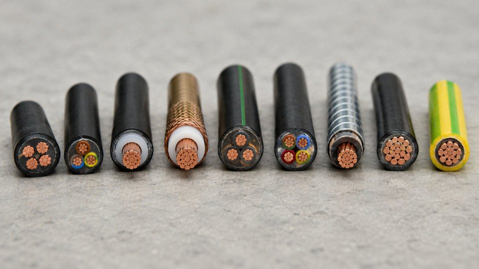
SWA/AWA Armored Cable
Round steel wires (SWA) or aluminum wires (AWA) visible under the outer PVC sheath — not a spiral braid, but individual round wires laid helically. This is the standard for UK direct burial and international plant cabling where mechanical damage is a real concern. AWA is specified where stray current corrosion or magnetic effects are a concern on single-core runs.
VFD Cable
Three-phase power cable with a symmetrical arrangement of ground conductors and either 100% braid or foil-plus-braid shield. Strip the outer jacket and the shield is immediately obvious. The print line will say VFD, drive, or variable frequency. Using standard THHN in a VFD application without proper shielding is a fast path to nuisance trips and bearing failures — the common-mode noise from an inverter output is genuinely destructive over time.
Using unshielded cable on VFD outputs longer than roughly 10–15 meters significantly increases common-mode current and accelerates motor bearing wear.True
Inverter switching generates high-frequency common-mode voltage that travels the cable shield back to the drive rather than through the motor frame and bearings when a proper shielded VFD cable with low-impedance ground conductors is used. Without shielding, that current path runs through the bearings.
Instrumentation Cable (Multipair Shielded)
Strip the jacket and you’ll see individual foil-shielded twisted pairs, each with a drain wire. The twist pitch is tight — typically 25–50 mm per turn depending on the frequency of the signal it’s carrying. Used for 4–20 mA analog loops and thermocouple extension. In practice, the biggest field error is cutting the drain wire short during termination; that defeats the shield at exactly the point where interference enters.
High-Temperature Silicone Wire
Unmistakable by feel — almost spongy, very soft, matte surface. Usually red or white. Rated 150–200°C. The print line will show SiR, silicone, or similar. Found inside motor junction boxes, oven wiring, and HVAC equipment. Don’t substitute PVC insulated wire in these applications; you’ll see insulation breakdown within weeks under sustained heat.
Welding Cable (Class K/M)
Remarkable flexibility from extremely fine bare copper strands — under magnification the cut end looks almost like a bundle of hair. Neoprene or EPDM jacket, rated for high cyclic current and rough physical abuse. Class K is the finer strand class; Class M is even finer. The print line calls it out explicitly. Using welding cable as a permanent building wire is a code violation in most jurisdictions, even though its flexibility makes it tempting.
Coaxial Cable (RG Series)
A clean cross-section cut reveals the concentric structure immediately: center conductor, dielectric foam, braid or foil shield, outer jacket. RG-6 is the standard for cable TV and broadband; RG-11 for longer runs where attenuation matters; RG-58 for legacy RF and some instrumentation. Impedance — 75 Ω for video/broadband, 50 Ω for RF — is printed on the jacket and is not interchangeable without signal loss consequences.
Knowing which family you’re dealing with before you touch a cable isn’t just good practice. It determines what tools, termination hardware, and downstream equipment are even compatible with what’s in your hand.
Frequently Asked Questions About Identifying Electrical Wire Types
Can I identify wire gauge without stripping the insulation?
Yes, and you should do this before stripping anything — especially on energized or potentially energized circuits. Measure the overall outer diameter with a digital caliper at a point where the jacket isn’t deformed. For THHN/THWN, the insulation wall at AWG 12 runs roughly 0.76 mm per side, so subtract about 1.52 mm total from your measurement to get the bare conductor diameter, then cross-reference against an AWG table. At AWG 12, the bare conductor sits around 2.05 mm; AWG 14 is closer to 1.63 mm. Those differences are real enough to catch with a decent $15–20 caliper — no need for anything precision-grade. Jacketed multiconductor cables add another layer, so you’ll need to know the jacket wall thickness as well, which is usually stamped on the print line or available in the manufacturer’s datasheet. The method isn’t perfectly precise, but it’s usually close enough to confirm a gauge before you commit to a termination.
My wire has no markings at all — is it safe to use?
Treat it as unverified until proven otherwise. NEC 110.3 and IEC 60364-5-52 both require that installed wiring be listed or approved; an unmarked cable satisfies neither requirement on its face.
Unmarked cable found on a job site is automatically non-compliant and must be replaced.False
Unmarked cable is unverified and potentially non-compliant, but it is not automatically condemned. However, it cannot be accepted into a permanent installation without laboratory verification of its ratings and construction. The burden of proof is on whoever is installing it.
Unmarked wire may be counterfeit, substandard, or salvaged from an application it was never rated for. Send a sample to an accredited testing laboratory — in North America, UL, CSA, or an OSHA-recognized NRTL; in Europe, a UKAS- or DAkkS-accredited lab. Do not use it in a permanent installation while you wait for results.
How do I tell the difference between aluminum wiring and copper-clad aluminum (CCA)?
Make a clean, perpendicular cut with a sharp utility knife or cable cutter and look at the cross-section under a loupe or magnifying glass. CCA shows a visible orange-red copper ring wrapped around a silver aluminum core — usually a few hundred microns of copper, enough to see clearly at 5–10× magnification. Solid aluminum is uniformly silver-gray all the way through. This matters enormously: CCA is prohibited for branch circuit building wiring in many jurisdictions, and its current-carrying capacity is lower than its copper-looking color implies. Terminating CCA conductors with hardware rated only for copper is a fire risk.
What is the safest way to test old wiring in a house built before 1980?
Assume aluminum wiring is present until you confirm otherwise. Look for CO/ALR-rated devices at outlets and switches — that marking indicates hardware designed for aluminum termination. At the panel, check for discoloration, char marks, or melted insulation around breaker lugs, which are classic signs of overheating at improperly torqued aluminum connections. The CPSC has documented roughly 55 times higher fire risk with improperly terminated aluminum branch circuit wiring compared to copper. Have a licensed electrician verify the full installation, and apply an identification and inspection sticker system after any remediation so the next person in the panel knows what they’re looking at.
Does wire color always mean the same thing?
No. Color conventions diverge significantly between NEC (North America), IEC 60446 (Europe), AS/NZS 3000 (Australia), and DC wiring systems. Color can also fade over decades, get re-taped by a previous installer, or simply be wrong in older or amateur work. Never rely on color alone. Cross-check against the print line and any available circuit documentation. On international projects — a container-built skid assembled in one country and installed in another, for instance — color conflicts are genuinely common and worth a dedicated review before commissioning.
How do I identify the voltage rating of an unmarked cable?
Insulation wall thickness gives a rough starting point. IEC 60502 specifies minimum insulation thickness by voltage class: for XLPE at 16 mm², a 0.6/1 kV cable requires roughly 1 mm minimum insulation wall. Thicker walls generally indicate higher voltage ratings, but don’t extrapolate too aggressively — some cables use thick insulation for mechanical protection, not voltage class. A dielectric withstand test (hipot test), performed by a qualified technician with properly rated equipment, can verify voltage rating directly. That’s the only reliable method when markings are absent. Don’t guess and install.
When ordering replacement cable internationally, how do I specify what I need from only an old sample?
Measure conductor cross-section in mm², count the conductors, identify conductor material (copper or aluminum), insulation compound (PVC, XLPE, rubber, LSZH), jacket type, voltage rating, temperature rating, and note any armoring or shielding. Then identify the applicable standard — IEC, NEC, BS, or GB/T. That full specification is what a supplier actually needs; “same as the old cable” is not workable across borders. Jinda’s technical support team can cross-reference a sample description against IEC, GB/T, and other standards to recommend the correct equivalent from their product range, which is genuinely useful when you’re working from a worn cable with a half-legible print line and a project deadline.
Sourcing Verified, Correctly Marked Cable for International Projects: What to Demand from Your Supplier
Knowing how to identify a cable is only half the job. The other half is making sure the cable you’re ordering actually is what the supplier says it is — before it’s installed in a building, buried underground, or shipped to a site where returning it costs more than accepting the problem. This is where identification knowledge becomes procurement discipline.
Mandatory Marking Requirements: What Should Be on the Jacket
Any cable destined for a serious commercial or industrial project should carry continuous jacket printing that never repeats at intervals longer than roughly 500 mm. That print line needs to include the manufacturer’s name, cable type designation (e.g., NYY-J, THWN-2, N2XY), rated voltage, conductor cross-section and number of cores, temperature rating, and year of manufacture. IEC 60702 and UL 83 both specify what that information must include — and a supplier who can’t tell you which standard governs their print line probably isn’t meeting either one.
One quick test: wipe the jacket print with a cloth dampened with acetone or MEK. Legitimate embedded printing stays intact. Ink-stamped counterfeits wipe clean. It takes about 10 seconds and has saved more than a few project managers from a container full of substandard material.
Test Reports and Certifications: What to Actually Request
A certificate of conformity from the factory itself means relatively little without third-party backing. For IEC-market projects, request IEC 60228 conductor class verification (this tells you the conductor actually meets dimensional and resistance tolerances, not just weight), and IEC 60332 flame test results categorized per EN 50575 — Cca or B2ca for commercial buildings in EU countries. If the cable is LSZH-jacketed, IEC 61034 smoke density data should accompany it.
For North America–destined cable, UL listing is non-negotiable. For China-domestic supply, CCC certification applies. ISO 9001 factory certification is a baseline indicator of process control, though it doesn’t substitute for product-specific test reports. Always check that test report lab accreditation numbers are real and traceable — a photocopy with no issuing lab, no accreditation body reference, and no date is a red flag, not documentation.
IEC 60228 specifies minimum conductor cross-section tolerances and DC resistance limits for conductor classes 1 through 6, allowing buyers to independently verify whether a delivered conductor matches its stated size.True
IEC 60228:2004 Table 1 and Table 2 provide maximum DC resistance values at 20°C for each cross-section and conductor class, which a buyer can verify using a four-wire resistance measurement on a sample length without any specialized lab equipment.
Traceability: From Drum Label to Production Record
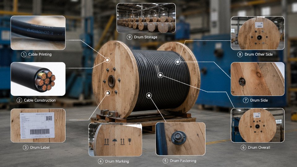
Every cable drum should ship with a label showing production batch number, cable length (measured length, not nominal), net and gross weight, and manufacturing date. That batch number should cross-reference to the factory’s internal quality control records — conductor material COA, extrusion line parameters, spark tester log. On larger contracts, ask whether those records are available for audit. Reputable manufacturers keep them. Others get evasive.
What a Factory Audit Actually Reveals
If you’re placing a contract above roughly $200,000–300,000 USD, a factory audit is worth the cost. Look for in-house conductor drawing equipment, which means the manufacturer controls alloy composition and temper rather than buying whatever rod the spot market offers that week. Dedicated extrusion lines per insulation compound type prevent cross-contamination between PVC, XLPE, and LSZH — mixing compounds even accidentally produces cables that pass visual inspection and fail in service. Calibrated spark testers on every insulation line are standard practice at any serious plant; their absence is a serious concern.
Jinda’s five production bases across China, covering 470,000 m² of manufacturing space with over 1,000 employees, run integrated R&D, production, and after-sales operations — the kind of infrastructure that supports consistent documentation and marking compliance across large, multi-shipment international contracts. Exporting to 50+ countries since 1987 means the quality system has been tested against real international project requirements repeatedly, not just on paper.
Pre-Shipment Inspection for Bulk Orders
For any cable procurement above roughly $100,000 USD, commission an independent pre-shipment inspection through SGS, Bureau Veritas, or Intertek. A proper PSI covers dimensional checks against IEC tolerances, four-wire conductor resistance measurement per IEC 60228, a voltage withstand test, and marking verification. It typically costs $800–2,500 USD depending on quantity and scope — a fraction of the cost of a failed installation or a regulatory rejection at the border.
Counterfeit and substandard cable is a real market problem, particularly on price-driven tenders. The conductor diameter on a nominal 2.5 mm² cable can be undersized by 8–12% and still look correct to the eye. Insulation walls below IEC minimums pass casual inspection but fail dielectric testing. The documentation practices described here aren’t bureaucratic overhead — they’re the only reliable way to confirm that the wire you’re identifying in the field actually matches the specification you approved in procurement.