Misidentifying the type of electrical conductor running through or above your site is the kind of mistake that compounds fast. A maintenance crew that treats a shielded medium-voltage cable as though it behaves like a bare overhead line will use the wrong test equipment, apply the wrong clearance distances, and potentially schedule the wrong outage window — all before anyone touches a tool. The procurement side is just as unforgiving: ordering ACSR conductors when your project specifies armored underground cable, or vice versa, can stall a construction schedule by weeks and leave you holding material that won’t pass the spec review.
Power lines are typically bare or lightly weatherproofed conductors strung on towers or poles, operating anywhere from 4 kV distribution up to 765 kV transmission, with no meaningful insulation resistance by design. Cable lines run underground or inside structures, are fully insulated and often armored, and generally operate in the 0.6/1 kV to 35 kV range for distribution networks. The physical structure, installation environment, weight, and test behavior are all fundamentally different.
What makes this genuinely tricky in the field is that the two systems increasingly share the same corridors — overhead lines transitioning to underground cable at substation entry points, hybrid rural-to-urban feeders, and retrofit projects where old overhead routes get buried in stages. You can be looking at both on the same job without a clear handoff marker. Understanding what each system actually looks like, weighs, tests like, and is designed to do is the only reliable way to tell them apart.
Physical Construction: What Each Type Looks Like Up Close
Pick up a bare ACSR conductor and an armored MV cable side by side and there is no confusion — they are almost comically different objects. The problem is that most people never hold them together, and in the field or during a rushed goods-in inspection, one glance is all you get.
Bare Overhead Conductors (ACSR, AAC, AAAC)
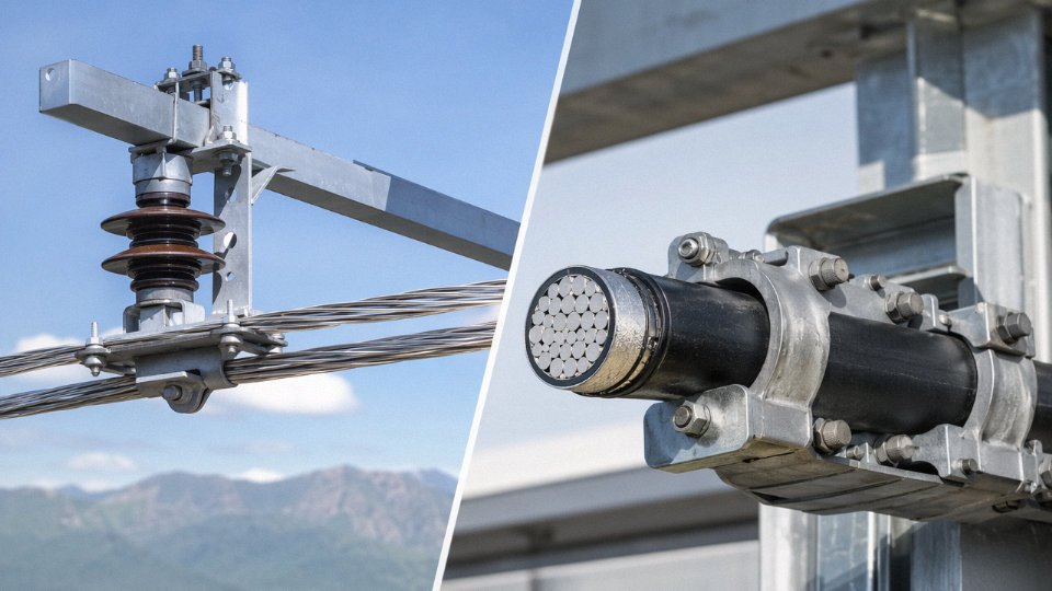
A standard ACSR conductor is exactly what it looks like from the ground: exposed metal, nothing else. The central core is galvanized steel wire — typically 1, 7, or 19 strands depending on the conductor size — wrapped concentrically by layers of hard-drawn aluminum strands. There is no insulation layer, no jacket, no sheath. The design is intentional; air is the insulating medium, and the tower or pole geometry maintains clearance.
On a 150 mm² ACSR, you are looking at roughly 394 kg per km. That weight figure is almost entirely structural metal. The surface weathers to a dull silver-grey with a faint oxide patina — aluminum oxide, which forms within days of exposure and actually protects the conductor from further corrosion. Under polarized light or close inspection, the individual wire strands spiral visibly around the core. No color coding, no markings that matter for identification purposes. What you see is what it is.
AAC (all-aluminum) and AAAC (all-aluminum alloy) conductors follow the same principle — stranded, bare, metallic — just without the steel core. Slightly lighter, slightly less sag-resistant, but visually near-identical from any practical distance.
Aerial Bundled Cable — The One People Get Wrong
ABC cable is the most frequently misidentified product in procurement and in the field. It hangs on poles like overhead line, it uses pole-mounted hardware, and it sits in the same general category in many utility specifications. But it is not bare overhead line.
Each conductor core in an ABC assembly is individually insulated — typically with black XLPE or HDPE rated for UV and weather resistance — and the cores are twisted together into a bundle. The outer surface is black, slightly waxy-looking, and you cannot see any bare metal without cutting into it. In LV ABC configurations (commonly 0.6/1 kV), you will usually see three phase conductors twisted around a bare or insulated neutral messenger. The neutral messenger is sometimes the only bare element in the whole assembly, which adds to the confusion.
If it is black, bundled, and on a pole but clearly has a plastic outer surface rather than exposed metal, it is almost certainly ABC. Treat it as insulated cable for safety purposes — which it is.
Underground Power Cable Construction, Layer by Layer
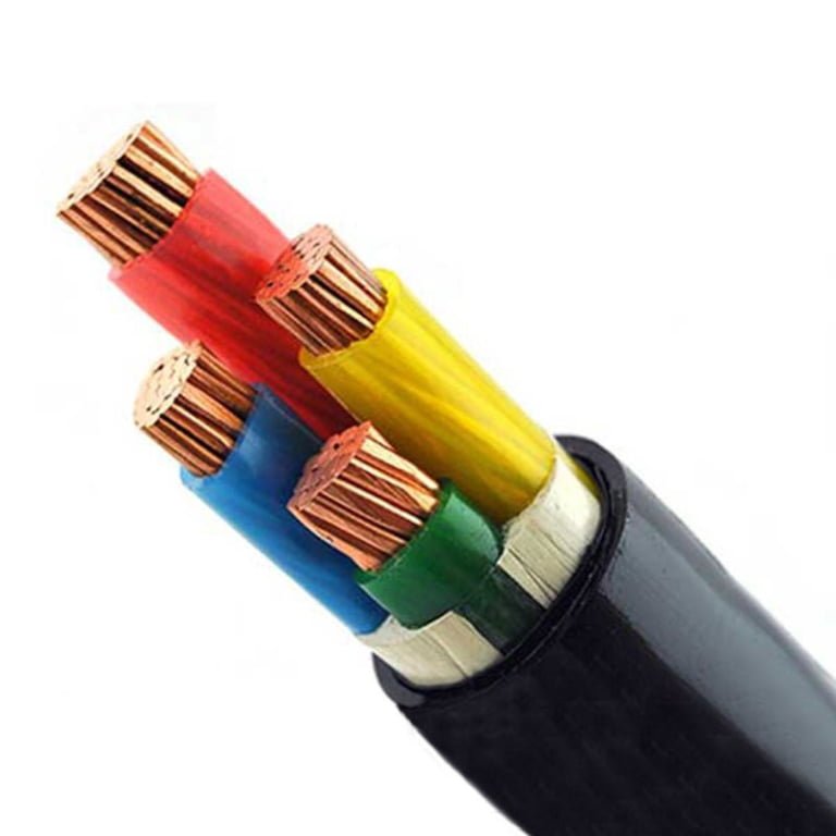
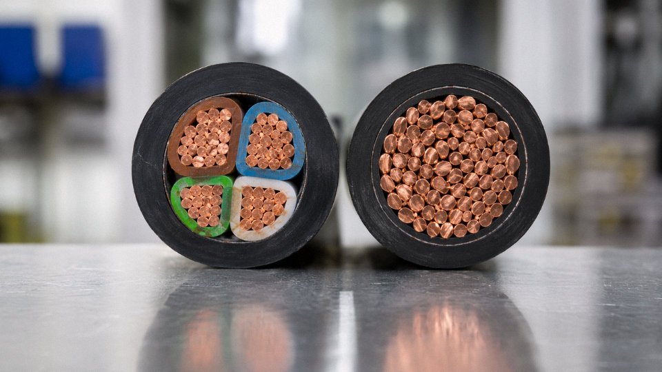
A medium-voltage XLPE armored cable — say, an 8.7/15 kV three-core design — is a completely different object in cross-section. From the center outward: the conductor itself (stranded copper or aluminum), then a semi-conductive conductor screen that smooths the electric field gradient, then the XLPE insulation (this is the primary voltage-withstanding layer), then a semi-conductive insulation screen, then a metallic screen of copper tape or copper wires that provides fault current return and electrostatic shielding, then an inner polymeric sheath, then steel wire or steel tape armor for mechanical protection, and finally an outer jacket — usually black PVC or HDPE.
Each layer earns its place. Strip one out and you have a failure mode. The XLPE insulation alone on a 15 kV cable is typically 4.5–5.5 mm thick; the whole cable assembly for a 150 mm² three-core armored MV cable will weigh somewhere in the range of 1,800–2,200 kg per km, depending on conductor material, armor type, and jacket specification. Compare that to the 394 kg/km of a bare ACSR at the same conductor cross-section and you understand immediately why cable installation costs, pulling tensions, and civil work are so much heavier.
Color Coding: Useful Clue, Not a Definitive Test
IEC standards and most national derivatives use jacket and core colors as identification aids, not absolute identifiers. Black is the dominant outer jacket color for UV-exposed and direct-buried cables. Orange outer jackets appear on some medium-voltage distribution cables in European utility specifications and on certain mining cables. Red sometimes indicates fire-resistant or fire-retardant cables. In practice, jacket color tells you something about the application category but does not confirm voltage class or construction type without a marking check or datasheet.
Core insulation colors — brown/black/grey for phases and blue for neutral in IEC systems, or black/red/blue/white in some national variants — matter more for internal identification during jointing and termination than for product-level identification at goods-in.
Jacket color alone reliably identifies a cable's voltage classFalse
Color conventions vary by national standard, utility specification, and manufacturer practice. A black outer jacket appears on both 1 kV LV cables and 33 kV HV cables. Voltage class must be confirmed from cable markings, datasheets, or drum labels.
Quick-Reference Construction Comparison
| Product Type | Insulation Present | Armor Present | Typical Outer Color | Typical Environment | Approx. Weight (150 mm² equiv.) |
|---|---|---|---|---|---|
| ACSR overhead conductor | No | No | Silver-grey (metallic) | Overhead, open air | ~390–400 kg/km |
| ABC aerial bundled cable | Yes (per core) | No | Black (XLPE/HDPE) | Overhead on poles | ~400–700 kg/km (varies by config) |
| LV underground cable (0.6/1 kV) | Yes | Usually yes | Black or grey | Direct buried / duct | ~700–1,200 kg/km |
| MV underground cable (6–35 kV) | Yes | Yes | Black or orange | Direct buried / duct | ~1,800–2,200 kg/km |
| HV underground cable (66–220 kV) | Yes | Yes (lead/wire) | Black | Buried / tunnel | ~5,000–15,000+ kg/km |
Weight ranges depend on conductor material (copper vs. aluminum), number of cores, armor type, and jacket thickness. Treat these as order-of-magnitude planning figures, not procurement specs.
Visual and Environmental Context Clues You Can Use Without Touching Anything
The safest identification happens before your hands get anywhere near the conductor. Train yourself to read the environment first — the hardware, the terrain, the markings — and you’ll usually have a confident classification before you’ve taken a single measurement.
Overhead Power Line Indicators
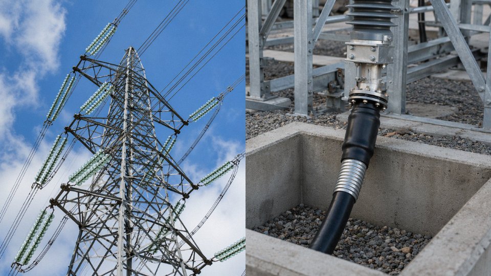
The most obvious sign is the support structure. Steel lattice towers, H-frame structures, or wooden poles with cross-arms all tell you the conductors are hanging in open air. Look at the attachment points: glass disc insulators, brown glazed ceramic strings, or grey composite polymer insulators are the mechanical and electrical interface between conductor and structure. No insulator means no bare overhead line — it’s that simple. The number of insulator discs in a string loosely indicates voltage class; a single disc handles roughly 10–15 kV of impulse withstand, so count them if you’re trying to estimate system voltage from a distance.
Conductor sag is another reliable indicator. Bare ACSR and AAAC conductors hang in a visible catenary curve between spans. Span lengths on distribution lines typically run 50–150 m; transmission lines can stretch 300–500 m or more between towers, with sag that looks almost lazy in hot weather — thermal expansion is real, and a 150 mm² ACSR conductor can elongate enough over a 400 m span to drop the mid-span clearance by 0.5–1.0 m between a cold winter morning and a summer afternoon peak load. You’re not going to see that kind of sag on a cable.
At extra-high-voltage levels (roughly 330 kV and above), a faint audible hum or crackling near the line on humid days is corona discharge. It’s not always present, but when you hear it, you’re standing near a bare EHV overhead conductor, full stop. Bird guards (plastic spiral deflectors) and Stockbridge vibration dampers — those dumbbell-shaped weights clamped near the suspension clamps — are also exclusively an overhead line feature.
No ground-level conduit, duct bank, or trench markers? Overhead. It’s a useful negative check.
Underground Cable Indicators
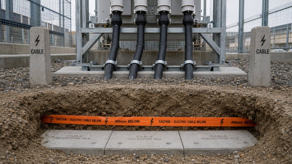
Surface-level route markers are the first thing to look for — small concrete or plastic posts stamped “CABLE” or marked with a lightning bolt symbol, spaced at intervals along the route. At excavation sites, if you see orange or red warning tape appearing roughly 300–500 mm below grade (IEC practice; local standards vary — some utilities in the Middle East go shallower, some European transmission owners go deeper), there’s a cable below it. Concrete cable tiles serve the same protective and warning function on higher-voltage circuits.
Hand-holes, cable pits, and joint bays at grade level are strong indicators. Sealing ends or stress cones emerging from the ground into the base of a transformer or ring main unit — those tapered, sometimes heat-shrunk or porcelain terminations — confirm underground cable beyond any doubt.
Aerial Bundled Cable (ABC) — Easy to Misread
ABC hangs between poles like an overhead line but it’s insulated. The bundle is typically black (UV-stabilized HDPE or XLPE jacket), relatively low to the ground on LV distribution — usually 4–8 m — and service drops curve off toward buildings where a weatherhead fitting marks the entry point. ABC either uses a bare messenger wire as the mechanical support with insulated phase conductors bundled around it, or it’s a self-supporting design with the neutral core doing double duty.
Here’s the caution: a weathered or mechanically damaged ABC jacket can split and curl back, exposing bare aluminum beneath. From twenty metres away on a grey day, that section looks exactly like bare overhead conductor. Treat any unknown aerial conductor as energized bare wire until you’ve confirmed otherwise with a hot-stick voltage detector. This isn’t overcautious — it’s the reason linemen still get burned on what they assumed was “just the bundled cable.”
Pre-Site Classification Using Available Records
Do this before you leave the office. Google Earth’s satellite and Street View layers will show you towers, poles, visible conductor sag, and ground-level markers clearly enough to make a preliminary call on most urban and suburban circuits. Utility GIS portals — where accessible — carry layer-separated overhead and underground data with voltage class attributes.
On single-line diagrams following IEC 60617, overhead lines are shown with the standard “fence” symbol (a line with short diagonal hatching below), while underground cables use a line with a solid rectangle or filled segment. These symbols are not universally consistent across older as-built drawings, so always cross-check the legend on the specific drawing set you’re reading. Drawings from the 1970s and 1980s especially can be idiosyncratic.
IEC 60617 uses distinct graphical symbols to differentiate overhead lines from underground cables on single-line diagramsTrue
IEC 60617 is the international standard for graphical symbols used in electrotechnical diagrams, and it does define separate symbols for overhead lines and underground cables, though actual application in as-built drawings varies by contractor and era.
Get the as-built drawings, check the GIS, note the surface markers — then confirm on site with non-contact voltage detection. That sequence keeps the identification process systematic and, more importantly, keeps people from touching something before they know what it is.
Reading Cable Drum Markings, Data Plates, and Product Codes
Walk into most warehouses receiving a mixed shipment of conductors and cables and you’ll find someone squinting at a drum label trying to figure out what they’ve actually got. Electrical testing isn’t always practical at goods-in, and the physical product might still be fully reeled. The markings on the drum and the product code printed on the outer sheath are, in practice, the fastest and most reliable identification tools available — if you know how to read them.
IEC 60228 Conductor Class and What It Tells You Immediately
The conductor class designation — Class 1, Class 2, Class 5, and so on under IEC 60228 — appears on the drum data plate and is sometimes printed directly on the cable sheath at regular intervals. Class 1 is solid conductor, Class 2 is stranded but still a fixed installation conductor, and Class 5 is flexible stranded. Here’s the practical point: if you see Class 1 or Class 2 in a cable’s data plate, you are almost certainly looking at an insulated power cable intended for fixed installation. Bare overhead conductors like ACSR or AAC don’t carry an IEC 60228 class designation in their product labeling — they reference conductor standards like IEC 61089 instead. The presence of a conductor class number is a strong signal that insulation layers exist.
Decoding an IEC-Style Cable Designation String
Take a designation like YJV22-8.7/15 kV 3×150 mm². Each segment carries specific meaning and together they make misidentification very difficult.
- YJ — cross-linked polyethylene (XLPE) insulation
- V — PVC inner sheath
- 22 — double steel tape armor with PVC outer sheath
- 8.7/15 kV — rated voltage: 8.7 kV phase-to-earth, 15 kV phase-to-phase, placing this squarely in medium-voltage underground distribution territory
- 3×150 mm² — three conductors, each 150 mm² cross-section
That string alone tells you it is an armored, medium-voltage underground cable. No ambiguity. The voltage designator, the armor code, and the insulation material codes are all present. Contrast that with an overhead conductor designation: ACSR 150/25. There is no insulation code, no voltage rating, no sheath reference. The two numbers are aluminum cross-section and steel core cross-section, full stop. The naming convention for bare overhead conductors simply has no place to put a voltage rating — because the conductor carries no insulation and the operating voltage is determined entirely by the tower and clearance design, not the conductor itself.
What a Properly Marked Drum Should Show
Under IEC 60500 drum marking practice, a compliant reel should carry: reel identification number, gross weight and net cable weight (separately — don’t confuse them), drum dimensions (flange diameter, traverse width), cable length in meters, direction-of-pull arrow, voltage rating, applicable standard (IEC, GB, BS, ASTM as applicable), conductor cross-section, and the manufacturer’s batch or heat code. The batch code matters for procurement traceability — it links back to the conductor material certificate and the production test records. Missing fields on arrival are worth querying before the drum leaves the loading dock.
Two Misreads That Cause Real Problems
A 0.6/1 kV rating printed on a low-voltage cable drum does not mean the cable is safe to approach or handle while energized. That marking describes the insulation’s rated voltage class, not a permission to work live. Plenty of incidents have happened because site workers assumed a “low voltage” label meant no serious hazard.
Going the other direction: the absence of any voltage marking on an ACSR or AAC conductor reel does not indicate low voltage. It indicates no insulation at all. That conductor could be strung at 110 kV or 400 kV depending on the network it’s destined for.
The absence of a voltage rating on an overhead conductor drum label indicates it is safe or low-voltage.False
Bare overhead conductors carry no voltage marking because they have no insulation — operating voltage is set by the network design, not the conductor itself. An unmarked ACSR drum could be destined for a 400 kV transmission line.
One more practical habit: the sheath print legend — that repeating text stamped along the cable jacket every meter or so — often contains the full designation string. If the drum label is damaged or missing, check the sheath. It’s usually enough to reconstruct the full specification.
Electrical Testing Methods That Confirm Cable vs. Overhead Line Classification
When visual inspection and drum markings leave any doubt, electrical testing gives you a definitive answer — provided you know which tests to run and what the numbers actually mean.
All of the following applies strictly to de-energized, isolated, and fully earthed conductors tested by licensed electrical personnel. This is not a DIY guide. If you are not qualified to perform HV insulation testing, stop at the identification stage and bring in someone who is.
Insulation Resistance Testing: The Fastest Discriminator
A Megger or digital insulation tester at 1,000 V DC is usually the first tool you reach for. The logic here is blunt: a bare overhead conductor — ACSR, AAC, AAAC, whatever the alloy — has no insulation medium at all. Touch the probes between conductor and any grounded reference point and you will read resistance values in the low kilohm range or outright zero, depending on surface contamination and ambient humidity. That is by design; the conductor relies on air clearance, not wrap.
A properly manufactured medium-voltage XLPE cable tells a completely different story. IEC 60502-1 sets minimum insulation resistance values scaled by conductor cross-section and temperature, but in practice a new or well-maintained 10 kV XLPE cable on a dry drum should read somewhere in the hundreds to low thousands of MΩ — often 500 MΩ to well over 2,000 MΩ per km at 20°C, depending on cable age, insulation grade, and moisture history. Anything below roughly 100 MΩ on a new reel deserves a hard look before acceptance.
A bare ACSR overhead conductor will show near-zero insulation resistance to a grounded reference because it has no insulation medium, while a new MV XLPE cable should read hundreds to thousands of MΩ under IEC 60502-1 criteria.True
Bare overhead conductors are designed to operate through air clearance, not dielectric insulation. IEC 60502-1 specifies minimum insulation resistance values for insulated cables, confirming the fundamental difference in measured IR between the two conductor types.
Tan Delta Testing: If Someone Asks for This, You Already Have a Cable
Tan delta, or dissipation factor testing, measures the ratio of resistive to capacitive current through the insulation — essentially how lossy the dielectric is. The test is physically meaningless on a bare conductor. There is no dielectric to characterize. So if a maintenance spec or a test certificate references tan delta, that document is describing a cable, full stop.
For new XLPE insulation, expect dissipation factor values well below 0.001 at 20°C and test frequency. Aged or moisture-contaminated insulation climbs above that threshold, sometimes sharply. The test won’t tell you conductor type, but its existence in a test requirement confirms insulated cable without any further argument.
TDR: Useful for Both, But the Signatures Differ
Time-domain reflectometry sends a fast voltage pulse down a conductor and reads back reflections from impedance discontinuities — joints, terminations, faults, and the far end. It works on both overhead lines and underground cables, which makes it less useful as a pure classification tool. What differs is the waveform character: a bare overhead conductor has relatively high characteristic impedance, typically 300–450 Ω depending on geometry, and a propagation velocity close to the speed of light in free space. A screened, armored XLPE cable sits much lower — characteristic impedance in the 30–60 Ω range is common — and propagation velocity drops to roughly 50–70% of c due to the dielectric constant of the XLPE insulation. If you pull up a TDR trace and the propagation velocity is noticeably slower than free-space, and the characteristic impedance is low, you are almost certainly looking at an insulated cable. The multiple impedance layers in a cable with separate screen and armor can produce secondary reflections that a bare conductor simply won’t generate.
DC Hi-Pot Testing: Applied Only to Insulated Cables, Never Bare Lines
DC high-potential testing applies a sustained elevated DC voltage — for a 6/10 kV cable, IEC 60502-2 specifies a test voltage on the order of 3U₀ (approximately 3 × 6 kV = 18 kV) held for 15 minutes during acceptance testing — to verify insulation integrity without destructive breakdown. The test protocol assumes a complete, continuous insulation system. Attempting this on a bare overhead conductor achieves nothing except an arc to the nearest grounded structure or equipment. The test voltage selection itself encodes the assumption of full insulation; the standard was never written with bare conductors in mind.
In practice, DC hi-pot is increasingly being replaced by VLF (very low frequency) AC testing on longer cable runs because DC testing can leave residual charge distribution in aged XLPE that creates localized stress, but that is a cable aging topic. The point here is narrower: if a commissioning checklist specifies hi-pot testing with a defined voltage and hold time against IEC 60502-2 or a similar cable standard, you are dealing with an insulated cable. No equivalent test exists for bare overhead conductors.
The pattern across all four methods is consistent. Bare conductors have no insulation to measure, characterize, or stress-test. Any test that targets insulation — whether it measures resistance, loss angle, dielectric response, or breakdown voltage — is, by definition, a cable test. If the conductor in question survives that test battery and returns valid numbers, it is insulated cable. That alone is sometimes the clearest confirmation a procurement or commissioning team can get.
Installation Environment and Route Evidence: Reading the Landscape
Before anyone picks up a shovel or a test instrument, the surrounding infrastructure will usually tell you what you’re dealing with — if you know what to read. This is especially true on brownfield sites, road crossings, and agricultural land where buried cables share corridors with other services and the only documentation is a decade-old PDF someone emailed from the utility company.
Underground Route Indicators in Urban Environments
In built-up areas, buried power cable routes are marked by a fairly consistent set of physical signatures. Cable route signs — small yellow or orange posts, sometimes flat flush markers — appear at 50–100 m intervals along the route centerline, consistent with IEC and EN marking practice. Don’t assume they’re always upright or visible; in practice, construction traffic buries them or contractors relocate them without updating drawings.
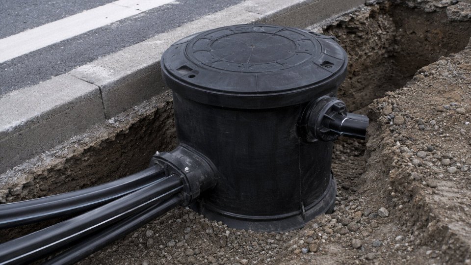
More reliable are joint bay covers: rectangular cast iron or precast concrete lids, typically 600 × 900 mm or larger, set flush with road or pavement level. These mark splice pits where cable drum lengths are joined — usually every 500–800 m depending on drum capacity and cable weight. A 150 mm² XLPE armored cable runs around 1,800–2,200 kg/km (varying with armor type and jacket material), which limits practical drum lengths and forces more joints than an overhead line of equivalent route length would ever need.
Industrial facilities often have cable trench covers running in rows between switchgear buildings and transformers — steel or GRP grating over concrete trenches. Substation buildings with low-level louvered vents near ground level usually indicate a cable cellar below. If you see duct bank marker posts along a site road edge, there’s almost certainly a multicore or multi-circuit underground installation running below.
Underground Route Indicators in Rural and Agricultural Land
Rural routes are messier to read. The first real clue often comes during topsoil stripping — warning tiles (usually red or orange clay tiles, or plastic strips reading “ELECTRIC CABLE BELOW”) appear roughly 300 mm above cable centerline, which itself sits at 0.7–1.2 m depth for medium-voltage cables under agricultural land per IEC 60364 guidance. Shallower burial is common under private land with no road loading; deeper installation is used under roads, rail crossings, or where freeze-thaw cycles are severe.
Sometimes it’s just a layer of sharp sand that stops the excavator operator — that’s a low-cost protection method used in older UK and European installations. If your team hits sand in a trench profile where the soil changes abruptly, stop and hand-dig.
Plastic warning tape 300 mm above the cable is now standard but was inconsistently applied in installations before the mid-1990s. Don’t rely on its absence to conclude there’s no cable.
Overhead Line Route Indicators
Overhead routes announce themselves. The most obvious sign is a right-of-way clearance corridor — a strip of land kept clear of tall vegetation, typically 10–30 m wide depending on voltage and national grid operator requirements. Tower or pole foundations appear at regular intervals: roughly 200–400 m spans for transmission towers, 50–80 m for distribution poles, though terrain forces variation. Anti-climbing guards (barbed or spiked plates) fitted to tower leg faces at 3–4 m height are a visual confirmation you’re looking at a high-voltage structure.
Transition Points: Where Both Types Meet
The sealing end location — where an underground cable rises to connect to an overhead line at a pole or compact substation — is one of the most information-rich spots on any route. You’ll see the cable armor grounded at the base, the stress cone and sealing end housing at the top of the riser, and surge arresters mounted adjacent to handle the switching transients that overhead lines generate and underground cables cannot shed as easily.
Surge arresters at cable-to-overhead transition points are installed primarily to protect the underground cable insulation, not the overhead conductorTrue
Overhead bare conductors tolerate transient overvoltages that would puncture XLPE or PILC cable insulation; arresters clamp the incoming surge voltage before it reaches the cable termination
Using Official Records Before Ground Disturbance
No amount of field observation substitutes for authoritative data. The UK’s LSBUD (Lines and Streets Below Underground Data) system, Australia’s Dial Before You Dig, and the US 811 one-call service all provide utility-confirmed route and type information before excavation begins. GIS layers from the local distribution network operator will typically show cable voltage, approximate depth, and route alignment — though as-built accuracy varies and should be cross-referenced against site survey data.
In my experience, the most dangerous situations arise when a contractor trusts a single source. Use the one-call system, pull the utility company GIS data, and walk the route looking for the physical markers described above. When those three sources agree, you can excavate with reasonable confidence. When they conflict, hand-dig trial pits.
Key Performance and Application Differences That Guide Specification Decisions
If you have already confirmed construction details and markings but still have doubt — or if you are writing a specification from scratch and need to back-verify that the product being quoted matches the intended duty — then looking at rated electrical performance is the most reliable final check. The numbers are not interchangeable between product families, and a mismatch here usually surfaces as a thermal or protection problem rather than an obvious visual defect.
Ampacity: The Heat Dissipation Argument
For the same nominal conductor cross-section, an overhead ACSR conductor in free air will carry noticeably more continuous current than a directly buried XLPE cable. The physics is straightforward: an overhead conductor radiates and convects heat in all directions; a buried cable is insulated from its surroundings by soil that may have a thermal resistivity anywhere from 0.7 K·m/W in moist sandy ground to well above 2.5 K·m/W in dry compacted clay. A 150 mm² ACSR in open air, under standard conditions (roughly 40 °C ambient, 0.5 m/s wind, 900 W/m² solar load), typically carries 340–400 A continuously. The same 150 mm² XLPE cable, direct-buried at 0.8 m depth in standard soil, gets derated to around 260–310 A depending on soil conditions, depth, grouping, and whether it is in conduit. That gap — sometimes 25–30% — is not a safety margin; it is a fundamental design difference. If someone quotes you a 150 mm² product and claims full overhead-line ampacity for a buried installation, that is a red flag worth querying immediately.
Inductance, Capacitance, and What They Tell You
Overhead lines have wide phase-to-phase spacing, typically 1–5 m at distribution voltages, which gives them relatively high inductive reactance — usually 0.35–0.40 Ω/km at 50 Hz. Underground cables pack all three phases close together inside the same trench, sometimes within centimetres of each other, so their inductive reactance drops to roughly 0.10–0.15 Ω/km. The flip side is that cable capacitance is substantially higher, often 0.2–0.4 µF/km for medium-voltage XLPE versus 0.008–0.015 µF/km for a comparable overhead line. If you have access to historical impedance measurements or power quality records on a circuit, those characteristic signatures can confirm product type. A circuit showing very low reactive voltage drop but drawing significant charging current at light load is almost certainly an underground cable, not an overhead line.
Short-Circuit Withstand and Metallic Screen Sizing
Underground cables are designed with a copper or aluminum screen that must be sized to carry the maximum prospective earth fault current for the fault clearance time expected from upstream protection — this is a mandatory design parameter under IEC 60502-1. Bare overhead conductors carry no such screen; fault current in an overhead network is handled by reclosers, expulsion fuses, and distance relays. The presence of a continuous metallic screen is therefore a physical differentiator that also has a rated electrical function. Stripping back a sample and finding no screen when you expected one — or finding a screen sized for only a fraction of the system fault level — suggests either the wrong product or a seriously under-specified cable.
Underground cables tested to IEC 60502 are required to pass water immersion testing; overhead conductors tested to IEC 61089 or ASTM B232 are not.True
IEC 60502-1 covers power cables up to and including 30 kV and includes water penetration and immersion tests. IEC 61089 and ASTM B232 govern round wire concentric lay overhead conductors and specify mechanical and electrical resistance requirements, not water immersion, since bare conductors are not designed for burial.
Requesting the wrong test certificate is a practical way to catch a misclassified product during incoming inspection. A supplier presenting an IEC 61089 mechanical test report in response to a request for an IEC 60502 cable qualification should prompt an immediate query about what they actually shipped.
Environmental Ratings and Lifecycle Maintenance
Underground cables carry IP ratings and are qualified for continuous water immersion because groundwater infiltration is a given over a 30–40 year service life. Overhead conductors are designed for sustained mechanical tension, UV exposure, wind and ice loading, and thermal cycling — none of which are the primary concerns for a buried cable.
The maintenance implications also differ in ways that can help you confirm what you have in the field. Overhead lines are visually inspectable by drone patrol, and most utilities run annual inspections that generate photographic records. A circuit with documented drone or helicopter patrol history is almost certainly overhead. Underground cables, by contrast, require time-domain reflectometry (TDR) for fault location and periodic partial discharge monitoring for insulation health assessment — neither of which makes any sense on a bare overhead conductor. If the client’s maintenance team is running TDR, you already have your answer. If they are asking about sag tables and galloping conductor clearances, that is an overhead line.
Common Misidentification Scenarios and How to Resolve Each One
Misidentification rarely announces itself. It shows up as a near-miss on a scaffold, a rejected goods delivery, or an excavator bucket through an energized cable. Each of the following scenarios is drawn from situations that come up regularly across distribution networks, construction sites, and procurement desks. The resolution steps are sequential for a reason — skipping ahead is where mistakes happen.
Scenario 1: The Weathered Aerial Cable That Looks Bare
ABC (Aerial Bundled Cable) insulation doesn’t last forever. UV exposure, ozone, and thermal cycling degrade polyethylene and XLPE jackets over 15–25 years, depending on climate and original compound quality. Once the outer jacket has cracked and shed in sections, the metallic strands beneath look almost identical to a bare ACSR conductor hanging on the same pole line.
Never assume it’s bare just because it looks bare. The remnant insulation between those visible strands may still be holding voltage. Standard practice: use a non-contact voltage tester (a good Fluke 1AC-A1 or similar) from a safe working distance before you do anything else — and if there’s any doubt about reach, a phase indicator on an insulated hot stick is safer still. Simultaneously, contact the network operator’s asset records team and request the line inventory for that pole run. Most utilities in developed networks have GIS records tied to pole numbers; even in markets where record-keeping is inconsistent, a distribution line supervisor can usually confirm cable type from installation records within a day. Do not climb, do not touch, do not lean equipment against that conductor until you have written confirmation.
Scenario 2: The Warehouse Receiving Dock With an Unlabeled Drum
Drum stencils get painted over, washed off in transit, or were never applied correctly to begin with. You receive a stranded conductor on a wooden reel and the paperwork is vague. Start with a calibrated digital vernier caliper on the cut end: measure individual strand diameter and count strands to back-calculate conductor cross-section, then compare against IEC 60228 Class 2 tables. Then look at the end face under a 10× loupe or a basic USB microscope. Insulated cable will show concentric layers — conductor, semiconducting screen, insulation (usually XLPE for anything above 1 kV), outer screen, bedding, armor, jacket. Bare conductor is just metal, all the way out.
If the end face is ambiguous or has been cut back too far, request the mill certificate and the factory test report from your supplier, citing IEC 60228 for conductor construction and IEC 60502-1 or -2 for the cable design. Any reputable manufacturer can produce these within 48 hours. Reject the delivery or quarantine the drum until documentation is in hand.
Scenario 3: The Renovation Excavation That Uncovers an Uncharted Conductor
Stop all mechanical excavation immediately. This is not a suggestion. An uncharted conductor could be a decommissioned service, a live 11 kV feeder, or a telecom cable — you genuinely cannot tell from visual inspection alone while it’s still buried.
Contact the local utility’s one-call center (811 in North America, equivalents elsewhere) and report the find. While waiting for their response, deploy a Cable Avoidance Tool set to power frequency (50 or 60 Hz) and the radio mode. A CAT will detect the electromagnetic field around an energized conductor without contact. If the instrument gives a signal, treat it as live HV until a utility technician confirms otherwise.
Cutting or moving an uncharted buried conductor before utility confirmation is required by law in most jurisdictions, not just best practice.True
In the UK, the Health and Safety at Work Act and the HSG47 guidance document legally require utilities confirmation before disturbing unidentified buried services. Similar statutory requirements exist in the US (OSHA 29 CFR 1926.956) and most EU member states under their respective excavation safety regulations.
Scenario 4: The Single-Line Diagram Showing Mixed Overhead and Underground Sections
This one trips up engineers ordering replacement product. A typical distribution feeder in a semi-urban environment might run as overhead ACSR from the substation to a riser pole, then transition to XLPE armored cable underground through a built-up area, then return to overhead at the far end. If the SLD doesn’t clearly mark that transition — or if you’re working from an outdated schematic — you can easily specify overhead conductor for a section that’s actually buried cable.
Locate the transition point symbols on the SLD (usually shown as a cable sealing end or riser symbol). Cross-reference with the physical route survey and the substation’s cable cellar records, which will document each cable’s type, cross-section, and circuit number at the point of termination. If those records conflict or are missing, a walkover survey of the pole run combined with a CAT scan of the route will resolve it. Confirm voltage class and installation method before writing any replacement specification — getting the voltage class wrong is a procurement error that can take weeks to unwind.
Scenario 5: The International Bid Where Overhead Conductor Is Priced as Insulated Cable
This happens more than it should, particularly in competitive tenders where a supplier substitutes a cheaper product hoping the buyer won’t look closely. The tell is almost always weight.
A 150 mm² ACSR conductor weighs roughly 394 kg/km. A 150 mm² XLPE armored underground cable — with insulation, semiconducting screens, copper tape screen, bedding, steel wire armor, and outer jacket — typically runs somewhere between 1,800 and 2,200 kg/km, depending on armor configuration and sheath material. That’s a 4-to-5× difference. Request the factory’s IEC 60502-1 or IEC 60502-2 type test certificate, which must include dimensional checks and conductor resistance at 20°C. Arrange a third-party inspection at the factory before shipment — a recognized inspection body can verify the cable drum weight against the certified design in a single visit. If the supplier resists third-party access, that resistance is itself informative.
Frequently Asked Questions
Can a power line ever be insulated?
Yes — aerial bundled cable (ABC) is a fully insulated overhead conductor, and the confusion it creates is completely understandable. ABC uses XLPE or HDPE insulation rated for outdoor UV exposure, moisture, and mechanical contact, so it looks and behaves like a cable product. In infrastructure terms, it is still classified as an overhead power line because it runs on poles through air. In product terms, it is a cable. The distinction matters for procurement: you order it to a cable standard (IEC 60502 or equivalent national specs), it ships on a drum, but your civil works budget carries essentially zero trenching cost. ABC is widely deployed in urban LV distribution and increasingly in MV networks in humid or heavily forested regions where bare conductors cause too many fault clearance headaches.
Is the black coating on overhead wires actually insulation?
This is one of the more dangerous assumptions on site. Many ACSR and ACSS transmission and sub-transmission conductors have a darkened surface — sometimes a thin anodized layer, sometimes a weatherproof grease treatment, occasionally just oxidation. None of it provides dielectric insulation. The rated withstand voltage is zero. Treat any overhead conductor as live and bare unless the product documentation explicitly states a rated insulation voltage and you can physically confirm it is ABC or an equivalent fully insulated product. In practice, if the conductor is strung at sub-transmission or transmission voltage (roughly 33 kV and above), assume bare.
A dark or coated surface on an overhead conductor does not indicate it is electrically insulated or safe to contact.True
Standard ACSR and ACSS conductors use only surface treatments for weather resistance; these have no rated dielectric strength and provide no protection against electric shock.
How deep is a buried power cable, and how do I find it?
Typical burial depths in standard soil run 0.5–0.7 m for LV cables, 0.7–1.0 m for MV, and 1.0–1.5 m for HV — though rocky ground, road crossings, and ducted installations change all of those figures considerably. Frost-line requirements push depths deeper in northern climates. For detection, use electromagnetic cable locators (which pick up the 50/60 Hz field from energized cables) combined with ground-penetrating radar, and always cross-reference against as-built drawings before any excavation starts. One method alone is not enough. A locator can miss a de-energized cable; GPR can misread in saturated clay.
What separates a power cable from a communications cable underground?
Power cables carry voltage and current. A cable locator will typically give a strong, clean signal from an energized power cable. Communication cables — coaxial, twisted pair — usually give a weaker signal and can be traced by injecting a signal into the metallic elements. Modern fiber optic cables present a completely different challenge: no metallic content at all in all-dielectric builds, so an electromagnetic locator will not find them. GPR is your tool there, though interpretation requires some experience. If you hit an unmarked underground route and your locator shows nothing, do not assume it is clear.
How do I find the voltage class of a cable?
The voltage designation is printed on the outer jacket at regular intervals — something like 0.6/1 kV or 8.7/15 kV. The first figure is conductor-to-screen (or earth), the second is conductor-to-conductor. You will also find it on the drum label and in the type test certificate. Never infer voltage class from jacket color or wall thickness alone; those vary by manufacturer, country standard, and production year. If the jacket markings are worn or absent, go to the drum data plate first, then the purchase order documentation.
Why does specifying the wrong product type cause real project damage?
Beyond the obvious — an overhead conductor in a trench has no armoring, no moisture barrier, and will fail within months — the procurement error cascades fast. Civil works are priced wrong from the start. Protection relay coordination, which is set up around cable impedance characteristics, will be incorrect. Grid code submissions may be rejected. Insurance cover for the installation can be voided. In competitive tenders, a specification error found at type inspection stage kills the bid or forces expensive substitution under time pressure.
Does Jinda manufacture both overhead conductors and underground cables?
Jinda’s product range covers both sides of the overhead-to-underground boundary: bare overhead conductors including ACSR, AAC, AAAC, and ACAR; LV and MV aerial bundled cable; low-voltage power cables; medium-voltage XLPE cables up to 35 kV; and high-voltage cables for utility-scale projects. That breadth is genuinely useful on transition projects — a rural electrification scheme, for instance, might need overhead ACSR on the long rural spans and then transition to armored underground cable for the final distribution run through a township. Sourcing both from one manufacturer simplifies type-test documentation, conductor sizing consistency, and logistics. Jinda’s engineering team can advise on product classification at the specification stage, which is the point where these decisions are cheapest to get right.
Specifying and Sourcing the Correct Product: A Practical Checklist for Buyers
By the time you reach this point in a project, you should have a clear read on whether you’re dealing with an overhead conductor or an insulated cable. The next problem is translating that understanding into a purchase order that doesn’t come back to haunt you during commissioning. Procurement errors at this stage — wrong armor type, wrong voltage designation, wrong conductor material — can mean months of delay and significant rework cost. The checklist below is sequenced deliberately; each step narrows the specification before the next one begins.
Step 1: Lock Down the Installation Environment Before Everything Else
Aerial open-air, aerial bundled, direct buried, ducted underground, submarine, or indoor — this single decision eliminates an entire product family before you’ve written a single other parameter. Specifying an XLPE armored cable when the route is entirely aerial on lattice towers wastes budget on armor and insulation you don’t need. Going the other way — specifying bare ACSR for a route that turns out to require 200 m of direct-buried crossing under a road — is genuinely dangerous. Get the route survey signed off first. Everything else follows from it.
Step 2: Define Voltage Class and System Earthing Properly
The U0/U designation matters more than most buyers realize. A cable rated 6/10 kV is not interchangeable with one rated 8.7/15 kV, even if the physical size looks similar on the drum. System neutral earthing method — solidly earthed, resistance earthed, or isolated neutral — directly determines U0, which in turn drives insulation thickness under IEC 60502-1. Isolated neutral systems can sustain a phase-to-earth fault for extended periods, so the cable insulation must be sized for that full phase-to-phase voltage continuously. Specify maximum fault duration alongside voltage class; omitting it forces the manufacturer to assume worst-case, which may oversize the cable and inflate cost unnecessarily, or lead to an underspecified product if the assumption goes the other way.
Step 3: Conductor Material and Cross-Section — Size It Properly
Aluminum costs roughly 40–60% less per kg than copper (depending on commodity pricing at time of order), but it runs about 1.6× the resistivity, so cross-sections increase. Neither is universally better. Copper suits tight conduit routes or high short-circuit duty; aluminum suits long rural distribution runs where weight and cost matter. Cross-section must satisfy both continuous load current — with derating applied for installation method, soil thermal resistivity (typically 1.0–2.5 K·m/W depending on soil type and moisture), and ambient temperature — and the short-circuit current per IEC 60949. Skipping the short-circuit check is a common oversight on procurement teams that work primarily from load schedules.
Step 4: Select the Right Mechanical Protection Level
| Armor Type | Typical Application | Watch Point |
|---|---|---|
| Unarmored | Indoor, open tray, fully ducted | No burial, no mechanical stress |
| Steel tape armor | Direct buried, light vehicle loading | Not for vertical drops or tensile load |
| Steel wire armor | Direct buried heavy stress, submarine approach, vertical risers | Single-core AC: use aluminum wire armor instead |
| Aluminum wire armor | Single-core AC cables, moderate mechanical duty | Avoids eddy-current losses from steel in AC single-core |
The eddy-current point on single-core cables is one that bites occasionally — a steel wire armored single-core cable on a 33 kV circuit can see measurable armor heating losses that add up over a cable run of any length.
Step 5: Request the Full Documentation Package
Don’t accept a cable without IEC 60502-1/-2 type test reports (for MV insulated cable) or IEC 61089 test records (for overhead conductor). Routine test records — conductor resistance, insulation resistance, voltage test — should accompany every drum. Ask for the mill certificate for the copper or aluminum rod used; traceability to raw material is the difference between a supplier who controls quality and one who doesn’t. Third-party certification (ISO 9001 at minimum, CE marking or local equivalent where the destination market requires it) and full drum labels with length, drum number, and manufacturing date should be treated as non-negotiable, not nice-to-have.
Jinda's cable products are manufactured across five production bases covering 470,000 m² and exported to more than 50 countries.True
This matches the company's published manufacturing and export profile and is a verifiable operational fact, not a marketing claim.
Step 6: Send Jinda a Complete Project Datasheet
A vague enquiry gets a vague quotation. Send project location, voltage class with U0/U designation, maximum load current, short-circuit level and duration, installation method, soil temperature and ambient temperature, UV exposure if aerial, required standards (IEC, BS, or local equivalent), delivery schedule, and quantity per drum length. Jinda’s engineering team targets a formal technical proposal within five business days for standard product families — faster if the specification is clean.
With five manufacturing bases, 470,000 m² of production capacity, and export experience built up since 1987 across more than 50 countries, Jinda carries both overhead conductor and insulated cable product families under one roof. That matters for projects with mixed routes — you’re not coordinating two separate supply chains. Technical support extends from initial specification through delivery, on-site installation guidance, and after-sales service, which in practice means a real engineer you can call when something doesn’t look right on arrival at site.