Mislabeling a signal cable as a control cable — or just grabbing whatever’s on the shelf because “it’ll carry the signal fine” — is one of those mistakes that doesn’t announce itself immediately. The system commissioning goes fine. Then, six months in, you’re chasing intermittent faults on a 4–20 mA loop, your PLC is throwing spurious trips, and nobody can figure out why because the wiring looked correct on paper. Ground loops, induced noise from a nearby 480 V run, degraded shielding that was never rated for the job in the first place — these aren’t exotic failure modes. They’re what happens when signal and control cable get treated as interchangeable. The downstream cost isn’t just a replacement cable; it’s technician hours, unplanned downtime, and in process industries, potential batch scrap.
Signal cables and control cables are not the same thing. Signal cables carry low-level electrical signals — typically below 1 V to 5 V DC at currents under 100 mA — and are engineered primarily for noise rejection and signal integrity. Control cables are built to handle 300 V to 600 V AC/DC at currents up to 20 A or more, prioritizing insulation robustness, mechanical durability, and safe power switching. Using one where the other is required causes either noise corruption, insulation failure, or both.
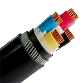
What makes this genuinely tricky is that the two cable types can look nearly identical on a reel — similar jacket colors, similar outer diameters, similar conductor counts. The differences that actually matter live in the conductor cross-section, the shielding architecture, the dielectric properties, and how the cable handles its specific electrical environment. Understanding those differences isn’t an academic exercise; it’s what determines whether your instrumentation reads true or drifts, whether your control circuit trips cleanly or arcs.
Core Definitions and Functional Roles: What Each Cable Type Is Actually Built to Do
Start with the basics, because the terminology gets blurry fast on real projects — especially when a purchasing manager is working from a BOM that just says “instrumentation cable” without further specification.
What a Signal Cable Actually Does
A signal cable is designed to carry low-energy electrical signals — not power — between a field device and a controller, recorder, or monitoring system. The operative word is information. You’re transmitting a 4–20 mA loop from a pressure transmitter, a thermocouple’s millivolt output (which might be 10 mV to 60 mV depending on type and temperature range), an RTD resistance reading, a pulse train from a shaft encoder, or a fieldbus frame from a PROFIBUS or HART device.
The voltages involved are typically below 1 V up to around 5 V DC in most analog instrumentation circuits, though some digital fieldbus lines run slightly higher. Currents are well under 100 mA — often in the microamp range for thermocouple circuits. That’s why signal cable construction prioritizes electrical integrity above everything else: tight impedance control, careful twist geometries on each pair, and shielding that actually works at the frequencies in play. A conductor cross-section of 0.2 mm² to 1.5 mm² is typical; you’re not trying to carry real current, you’re trying to preserve a signal that represents, say, a tank level reading accurate to ±0.1%.
The engineering failure mode here isn’t overheating or insulation breakdown. It’s noise — induced interference from nearby power cables that shifts a 4 mA reading to 4.3 mA, or corrupts a PROFIBUS frame enough to trigger a fault. In practice, a poorly specified signal cable in a motor control center environment can cause intermittent PLC faults that take weeks to diagnose.
What a Control Cable Actually Does
Control cable carries switched or continuous electrical power to devices that do something physical: solenoid valves, motor starters, contactor coils, pilot lights, electric actuators, relay coils, and similar loads. The cable isn’t conveying data — it’s delivering energy sufficient to move iron.
Rated voltages typically run from 300 V up to 600 V AC or DC, with conductor cross-sections commonly in the 0.5 mm² to 10 mm² range, depending on the load. A 110 V AC contactor coil drawing 1–2 A, a 24 V DC solenoid valve at 0.5 A, a panel indicator at 50 mA — all of these are control cable territory. Currents can reach 20 A or more on multi-motor control circuits. The design priority is reliable power delivery and mechanical durability: adequate insulation for the voltage class, enough copper to handle continuous or intermittent load without excessive voltage drop, and jacket materials suited for the installation environment (tray, conduit, or direct burial).
The Functional Boundary That Matters
Here’s the core distinction worth internalizing: signal cables preserve information, control cables deliver energy. A millivolt-level thermocouple output corrupted by noise gives you a wrong reading — and a wrong reading can mean a wrong control decision. A control cable that’s undersized for its load gives you a voltage drop, excess heat, or tripped breaker — and that means your actuator doesn’t fully open, or your contactor chatters.
Different failure modes, different design philosophies, different installation rules.
Hybrid and Instrumentation Cables — When One Jacket Makes Sense
Some projects use composite instrumentation cables that bundle signal pairs and control conductors under a single outer jacket. This is common in machine-tool wiring and packaged equipment where the OEM wants to minimize the number of cable runs between a control cabinet and a remote junction box.
Used correctly — usually in applications where the control conductors are low-voltage (24 V DC logic-level) and physically separated from the signal pairs within the cable — hybrid cable is a legitimate space-saver. Used incorrectly — say, pairing a 120 V AC motor starter circuit with a thermocouple pair in the same cable — and you’ve built your noise problem directly into the cable. Separate cables are almost always the right answer when control voltages exceed 50 V AC or when signal accuracy is genuinely critical.
Signal cables and control cables can be used interchangeably in most industrial installations as long as the conductor size is appropriate.False
They serve fundamentally different functions with different shielding, voltage ratings, and construction standards. Substituting one for the other risks signal corruption, insulation failure, or non-compliance with installation codes such as IEC 60332 and NEC Article 800.
Quick-Reference Comparison
| Characteristic | Signal Cable | Control Cable |
|---|---|---|
| Primary function | Transmit low-energy data/measurement signals | Deliver switched or continuous power to actuators and control devices |
| Typical voltage range | Below 1 V to ~5 V DC | 300 V to 600 V AC/DC |
| Typical current range | Under 100 mA; often microamp-level | Up to 20 A or more depending on load |
| Conductor size range | 0.2 mm² to 1.5 mm² (typical) | 0.5 mm² to 10 mm² (typical) |
| Example end-use devices | Thermocouples, RTDs, pressure transmitters, encoders, fieldbus nodes | Solenoid valves, motor starters, contactor coils, pilot lights, relay circuits |
The ranges above shift depending on the specific application — a heavy-duty multi-motor control panel pushes toward the upper end of conductor size, while a delicate strain-gauge circuit stays at the very bottom of the signal cable voltage range. These aren’t hard walls, they’re typical zones.
Internal Construction Compared: Conductors, Insulation, Shielding, and Jacket Materials
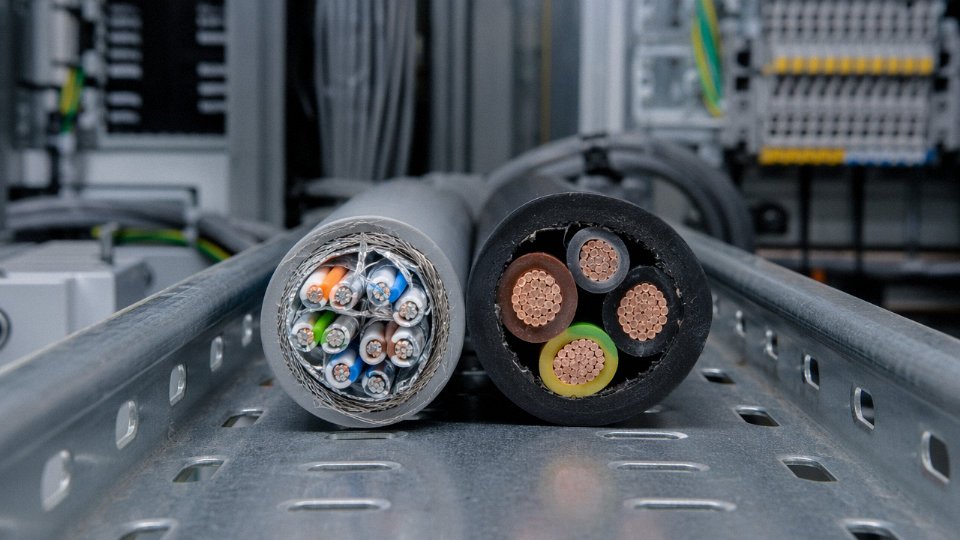
Pull a signal cable and a control cable from a cable tray side by side and cut them open — even a quick cross-section tells you they were designed for completely different jobs.
Conductors
Signal cable conductors are typically fine-stranded or solid tinned copper, cross-sections running 0.2 mm² to 1.5 mm², depending on the loop length and the instrument’s input impedance. The tin coating isn’t decorative; it stabilizes contact resistance over years of oxidation and the occasional soldering repair. Fine stranding keeps the bending radius tight, which matters when you’re dressing cables through an instrument marshalling cabinet where routing is genuinely cramped.
Control cable conductors are a different animal. Stranded copper from 0.5 mm² up to 10 mm² — sometimes higher for motor starter or solenoid valve circuits — because these conductors have to carry real load current, not just a few milliamps of sensor signal. The cross-section is chosen by voltage drop and thermal rating, not by signal integrity. Running a control cable conductor too small causes resistive heating and voltage drop under inrush; running a signal cable where a control cable belongs risks insulation breakdown the moment a relay coil fires.
Insulation
For signal cables, the insulation material actually changes the electrical behavior of the cable, not just its mechanical protection. XLPE, FEP, and high-purity PVC are common choices precisely because their dielectric constant is predictable and tightly controlled — capacitance per meter typically falls somewhere between 50 and 120 pF/m depending on conductor geometry and insulation wall thickness. High capacitance attenuates fast-rising signals and creates crosstalk between adjacent pairs. In a thermocouple loop running at millivolt levels, that matters immediately.
Control cable insulation is selected for voltage class and temperature rating, full stop. Standard PVC for 300 V or 600 V service works fine. Nobody is calculating dielectric constant for a 24 V DC digital output to a valve actuator.
Shielding Layers
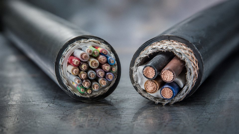
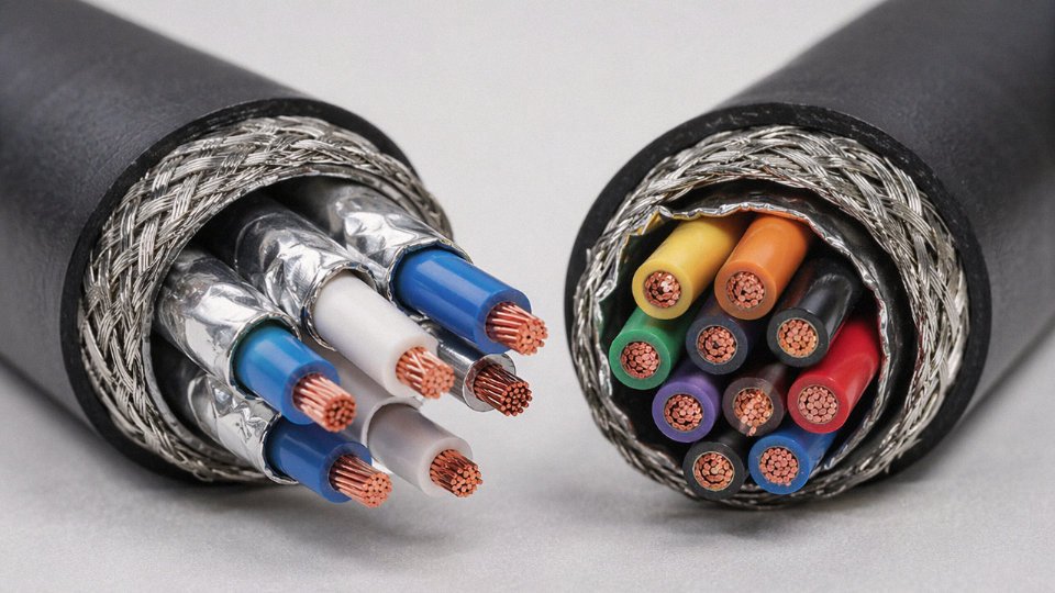
This is where signal cables get genuinely complex. Three distinct shield configurations show up in practice: individual pair foil shields, an overall foil shield, and braided copper shields, sometimes in combination.
Individual pair foils isolate channels from each other — critical when you have a 4–20 mA current loop running alongside a thermocouple circuit in the same cable. Without individual shields, the current loop induces noise directly into the millivolt-level thermocouple pairs. Overall foil or braid blocks external EMI from variable-frequency drives, welding equipment, radio transmitters, and whatever else is generating interference nearby.
Many control cables are unshielded, or carry only a simple overall foil intended for modest noise environments. That’s usually fine — a 120 V AC control signal to a contactor coil can tolerate far more interference than a 10 mV RTD signal.
Individual pair foil shielding in multi-pair signal cables is specifically designed to reduce crosstalk between channels, not just block external EMI.True
Each foil-shielded pair creates an isolated ground plane around that conductor pair, preventing capacitive and inductive coupling from adjacent pairs — a function that a single overall shield cannot provide.
Drain Wires and Shield Termination
Signal cables include a dedicated drain wire — bare or tinned copper — running in contact with the inner face of the foil. This gives you a reliable, low-resistance path to ground the shield without having to make contact with the foil itself, which tears if you look at it wrong. Ground this drain wire at one end only. Grounding both ends creates a ground loop that turns the shield into an antenna rather than a barrier. In practice, ground at the control room end; leave the field end floating. It’s one of those rules that gets violated during rushed commissioning and shows up three months later as an intermittent noise fault nobody can trace.
Outer Jackets
Indoor instrumentation environments often specify low-smoke zero-halogen (LSZH) or polyurethane (PUR) jackets on signal cables — LSZH because burning cable in a control room or platform should not generate toxic chlorine gas, PUR because it resists oil, abrasion, and repeated flexing in areas where the cable actually moves. Control cables in outdoor or underground routes more commonly use PVC, XLPE, or armored variants such as steel wire armour (SWA) or aluminum wire armour (AWA) where mechanical protection and moisture resistance dominate the specification.
Pair, Triad, and Multi-Conductor Construction
Signal cables are configured as twisted pairs or triads — the triad pairing makes sense for 3-wire RTD circuits where you need a sense conductor alongside the measurement pair. The twist pitch is a deliberate design parameter, typically specified in turns per meter, tightened to cancel electromagnetic interference through balanced coupling. A shorter lay length provides better noise rejection; manufacturers control this as a quality parameter, not an afterthought.
Control cables stack conductors in concentric layers without any precision twist-pitch requirement. The geometry serves pulling tension and fill factor in conduit, not signal integrity. That’s the right tradeoff for what control cables are asked to do.
Electrical Performance Parameters: Voltage Rating, Capacitance, Impedance, and Signal Integrity
The construction differences between signal and control cables aren’t academic — they translate directly into measurable electrical parameters that appear on data sheets, IEC certificates, and FAT test records. Getting these numbers wrong at the specification stage creates problems that are genuinely hard to trace once the cable is buried in conduit or tied into a tray.
Voltage Rating
Control cables are rated at 300/500 V or 450/750 V under IEC 60227, and 600 V under UL 508. Those ratings exist because control cables switch solenoids, starters, and auxiliary relays — real inductive loads with transient spikes. Signal cables are typically rated at 150 V or 300 V, which is adequate for instrumentation loops where the actual working voltage is rarely above 24 V DC. Some procurement engineers reflexively specify the higher-rated control cable “just to be safe,” but that’s usually wasted money — thicker insulation wall, higher cost per meter, and in some cases a stiffer, harder-to-route cable in densely packed marshalling cabinets.
Conductor Resistance and Loop Accuracy
For a 4–20 mA loop, conductor resistance is not a minor footnote. IEC 60228 Class 1 (solid) conductors at 1.5 mm² must stay at or below roughly 12.1 Ω/km at 20 °C; Class 2 (stranded) at the same cross-section is ≤13.3 Ω/km. Those tolerances matter because a 4–20 mA transmitter with a 250 Ω burden resistor at the receiver — a completely standard setup — will show a voltage drop across the cable resistance that the instrument cannot distinguish from signal. On a 500 m run with undersized or out-of-spec conductors, you can lose enough loop voltage to push the transmitter out of its compliance range altogether. Control cable conductors are held to reasonable resistance limits too, but the tolerance bands are wider because a few extra ohms don’t affect whether a relay coil pulls in.
Capacitance and RC Roll-Off
Low inter-conductor capacitance is probably the parameter that gets ignored most often in procurement, until it causes a problem.
For 4–20 mA analog loops beyond roughly 300 m, and especially for any pulse or high-frequency signal, you want capacitance below about 100 pF/m between any two conductors. When capacitance is high — say 200–300 pF/m, which you will find in some general-purpose twisted-pair cables — the cable forms an RC filter with the source impedance of the transmitter. The result is that fast pulse edges get rounded, response time slows, and on a HART-multiplexed loop, the 1200/2200 Hz HART signal can be attenuated to the point where the handheld communicator struggles to maintain a connection. In practice, cable capacitance depends on conductor spacing, insulation material (XLPE runs lower than PVC), and twist geometry — all things controlled in a proper instrumentation cable design but often left looser in a generic cable.
Characteristic Impedance
Control cables carry 50 Hz (or 60 Hz) power and switched DC. Characteristic impedance is irrelevant at those frequencies — the cable is far shorter than any meaningful fraction of a wavelength.
Signal cables used for digital fieldbus protocols are a different story entirely. PROFIBUS DP Type A cable requires 150 Ω ±20%; Foundation Fieldbus H1 specifies 100 Ω; RS-485 typically calls for 120 Ω. If the cable impedance doesn’t match the termination network, you get reflections. On a segment with multiple drops, those reflections superimpose and distort the signal waveform — not always enough to kill communication immediately, but enough to cause intermittent errors under noise or at segment length limits. I’ve seen plants where somebody swapped in a cheaper unspecified cable to finish a segment, and the fieldbus worked fine during commissioning with four devices, then started dropping frames at random after the segment was fully loaded.
PROFIBUS DP Type A cable must have a characteristic impedance of 150 Ω ±20% per IEC 61158True
IEC 61158 and the PROFIBUS specification both define Type A cable with a nominal characteristic impedance of 135–165 Ω (150 Ω ±20%), along with loop resistance ≤110 Ω/km and capacitance ≤30 pF/m. Using cable outside this specification risks signal reflections and frame errors, particularly on segments approaching maximum length.
Insulation Resistance and Leakage Paths
Both cable types should show insulation resistance above 100 MΩ·km per IEC standards, and most decent cables exceed that comfortably under new, dry conditions. The reason this parameter is more critical for signal cables is straightforward: in a high-impedance sensor circuit — a pH electrode, a thermocouple cold-junction compensator, a resistance temperature detector in a three-wire configuration — any leakage resistance between conductors or from conductor to shield creates a parallel current path that the measurement system sees as part of the circuit. At 10 GΩ sensor impedance and 1 GΩ cable leakage, you’ve introduced a 10% measurement error before you’ve even accounted for noise. Moisture ingress into a connector or a nick in insulation at a cable tray edge can drop insulation resistance by several orders of magnitude.
Mutual Inductance and Crosstalk
In a multi-pair instrumentation cable — say a 12-pair or 24-pair cable running 150 m through a process plant — the pairs are all electromagnetically coupled to each other. Tight, consistent twist pitch keeps this coupling low. Well-specified signal cable achieves crosstalk below −60 dB between adjacent pairs, which means the interfering signal is one-millionth the power of the wanted signal. That’s enough margin that a 4–20 mA signal on one pair won’t disturb a millivolt-level thermocouple signal on the pair next to it. Inconsistent twist pitch — which you do find in lower-cost cable where the lay length isn’t tightly controlled — raises crosstalk by 10–20 dB, and in a long parallel run that can be the difference between a clean reading and one that drifts in a pattern that correlates suspiciously with activity on a nearby loop.
Applicable International Standards and Certifications: IEC, UL, NEC, and Industry-Specific Codes
Getting the standard wrong costs more than a failed inspection. It can mean re-importing a full cable drum, a halted commissioning schedule, or — in hazardous-area installations — a voided insurance policy. Procurement engineers writing cable specifications for international projects need to map each cable type to its governing documents before a purchase order is raised, not after the goods arrive at port.
Signal Cable Standards
The primary IEC document for low-frequency signal cables is IEC 60189, which covers the physical layer requirements for telecommunication and signaling cables — conductor dimensions, insulation resistance, and attenuation limits at specified frequencies. For fieldbus wiring specifically, IEC 61158 is the reference you actually need. It defines the physical layer for PROFIBUS, Foundation Fieldbus, and HART, including characteristic impedance (typically 100–150 Ω depending on the fieldbus variant), cable capacitance limits, and termination requirements. In practice, fieldbus cable that technically passes IEC 60189 but doesn’t meet the impedance and capacitance windows in IEC 61158 will cause reflections and communication dropouts — a frustratingly intermittent fault to diagnose once a plant is running.
For instrumentation wiring in North American projects and increasingly in export specifications, ISA-5.1 governs instrument signal identification and loop documentation, while ISA-RP12.6 addresses wiring methods for intrinsically safe systems. If your project involves a DCS or PLC connected to field instruments in hazardous areas, ISA-RP12.6 is not optional reading.
Control Cable Standards
IEC 60227 covers PVC-insulated cables rated to 450/750 V — this is the baseline document for most multi-core control cables used in panel wiring and machine interlocks. IEC 60502-1 gets pulled into some control cable specifications by mistake; it covers extruded insulation cables from 1 kV upward, which is genuinely power cable territory. If a supplier quotes IEC 60502-1 for a 500 V control cable application, that’s a flag worth questioning.
On the North American side, UL 508 governs industrial control equipment including internal wiring methods, and NFPA 79 sets the electrical standard for industrial machinery — both documents reference acceptable cable types, routing segregation requirements, and conductor sizing. Projects destined for U.S. or Canadian facilities will almost always require UL-listed cable; a CE-marked cable without UL listing will typically fail AHJ (Authority Having Jurisdiction) inspection regardless of its electrical performance.
Hazardous Area Certifications
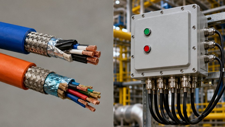
This is where getting it wrong carries the highest consequence. Signal cables installed in Zone 1/Zone 2 (IEC 60079 classification) or Division 1/Division 2 (NEC Article 505/501) must be rated for intrinsically safe (IS) circuits where applicable, with a blue outer jacket as specified under IEC 60079-14. That blue sheath is not cosmetic — it’s a visual safeguard against accidentally connecting IS circuits to non-IS wiring during maintenance, which is exactly the kind of error that happens on a night shift under time pressure.
Control cables in hazardous areas take a different path: separate conduit runs, EX-rated steel wire armoring, or both, depending on zone classification and the authority’s interpretation. ATEX certification covers European installations; IECEx is the internationally recognized equivalent and is increasingly accepted in Middle Eastern, Australian, and Southeast Asian projects without requiring local re-testing.
Fire Performance and LSZH Requirements
Offshore platforms, power plant cable decks, and public buildings — metro systems, airports, tunnels — routinely mandate IEC 60332-1 or IEC 60332-3 flame retardancy, IEC 60754 halogen content limits, and IEC 61034 smoke density compliance. LSZH (low-smoke zero-halogen) jackets are not a premium option in these environments; they’re a condition of project approval. Both signal and control cables used in those locations need fire-performance certification, and the test reports should accompany the delivery documentation.
China-Sourced Cable and GB Standards
Projects sourcing from Chinese manufacturers — which covers a large portion of global cable procurement by volume — will encounter GB/T 9330 for plastic-insulated control cables and GB/T 19666 for flame-retardant and fire-resistant cables. These standards are largely harmonized with their IEC counterparts, but not identical. Conductor resistance limits and insulation thickness tables can differ at specific cross-sections, and third-party type-test reports against the IEC version (not just the GB version) are worth requesting when the cable will be installed under IEC-governed project specifications.
Jinda holds ISO 9001 certification and maintains in-house high-voltage test laboratories capable of generating third-party-verifiable type-test reports, with CE and CCC marking available across its cable product ranges.True
Jinda's quality management system and laboratory infrastructure support compliance documentation for international projects, reducing the certification burden on procurement teams sourcing from China.
In practical terms, a procurement specification that calls out the IEC standard, the applicable fire performance class, the hazardous-area certification tier, and whether UL listing is required will eliminate most of the gray-area supplier substitutions that create inspection problems downstream. Vague specs invite vague compliance.
Installation Rules and Routing Practices: Separation Distances, Cable Trays, and Conduit Segregation
Getting the cable selection right and then routing signal cables next to power cables is one of the most consistent ways to waste an otherwise competent instrumentation budget. I’ve seen plants spend real money on shielded, impedance-controlled signal cable and then run it laced to a 480 V motor feeder for thirty meters. The result is millivolt-level noise riding on a thermocouple loop that was already only producing 10–50 mV full-scale. The measurement becomes worthless. The fundamental principle is simple: signal cables, control cables, and power cables belong in separate trays or conduits, period.
Minimum Separation Distances and Why They’re Not Suggestions
IEC 61000-5-2 and guidance from NECA and BICSI both point to roughly 150 mm of clear air between signal/instrumentation trays and control cable trays, and at least 300 mm between signal trays and any power cable tray. These figures assume standard construction with no additional metallic barriers. If you insert a grounded steel divider plate between trays, you can reduce those distances — typically down to around 50–100 mm — but that needs to be engineered and documented, not improvised on site. The distances scale with voltage and load current; a 6 kV medium-voltage tray running near capacity demands considerably more separation than a 24 VDC relay control circuit.
Tray Color Coding and Facility Documentation
Many facilities use physical color coding: green or blue trays (or tray labels) for instrumentation and signal cables, orange for control, red for power. This convention is not universally mandated — it varies by client standard, EPC contractor preference, and regional practice — but the important thing is that whatever convention a project uses gets locked into the Cable Segregation Philosophy document before the first tray goes up. Retrofitting a labeling system after construction is painful, expensive, and usually incomplete.
The 90-Degree Crossing Rule
When signal and control cables genuinely cannot avoid crossing a power cable route, they must cross at 90 degrees. This minimizes the coupled length between conductors. Parallel runs — even one or two meters of a signal cable lying alongside a 230 V control circuit — can induce noise in the range of a few millivolts to tens of millivolts depending on load current and cable spacing. For a 4–20 mA loop that’s usually survivable. For a Type K thermocouple producing maybe 4 mV at 100°C, it is not. Right angle crossing is one of those rules that feels pedantic until you’re chasing an unexplained process upset at 2 AM.
Grounding and Shield Bonding: Two Different Problems
Signal cable shields should be grounded at one end only — almost always the control room or marshalling cabinet end. This single-point grounding prevents ground loops, which can generate their own low-frequency noise currents directly through the shield and into the signal. Control cable armor, by contrast, is typically bonded at multiple points for mechanical protection and to provide a low-impedance fault current return path. Confusing these two approaches — multi-point bonding a signal shield, or single-point grounding control armor — causes real problems in both directions.
Single-point grounding of signal cable shields at the control room end prevents ground loop currents that would otherwise corrupt low-level analog signals.True
Ground loops form when two grounding points are at slightly different potentials; a continuous shield bonded at both ends creates a current path that introduces noise directly onto the signal conductor. Single-point grounding eliminates this loop while still providing electrostatic shielding.
Conduit Fill and Why Mixed Loading Violates More Than One Rule
NEC Chapter 9, Table 1 caps conduit fill at 40% of interior cross-sectional area for three or more conductors. That’s a thermal and pull-force constraint. But mixing signal and control cables in a single conduit also violates the electrical separation requirement entirely — the conduit wall provides essentially no inductive or capacitive isolation. Even if someone argues the fill calculation works out, you’ve just coupled your analog signal conductors directly to switching control circuits. Don’t do it.
Intrinsically Safe Circuits: The Audit Finding Nobody Wants
IS signal cables require physical separation from non-IS cables — a minimum of 50 mm within a cable tray per IEC 60079-14, or routing in a dedicated IS conduit. In practice, during ATEX or IECEx audits, inadequate IS cable segregation shows up more often than almost any other installation deficiency. The consequence isn’t just a finding; it’s potential de-certification of the hazardous area installation until corrective action is completed and re-inspected. If your facility is in a Zone 1 or Zone 2 classified area, segregate IS circuits completely and mark every termination clearly. Catching it during construction costs an afternoon. Catching it during an audit costs weeks.
Selecting the Right Cable for Your Application: A Decision Framework for Engineers and Procurement Teams
Getting to the right cable spec is rarely a single lookup. It’s a sequence of decisions, and if you skip a step or answer one question wrong, you end up with a re-pull, a noise problem, or — in a safety-instrumented circuit — a potential incident. Work through the following steps in order.
Step 1 — Classify the Circuit First
Before anything else, answer four questions about what the cable actually has to do:
- Is it carrying a measurement signal (sensor output, transmitter loop) or a switching/control action (relay coil, motor starter, solenoid)?
- What is the specific signal type — 4–20 mA analog, thermocouple millivolt, RTD resistance, digital fieldbus (PROFIBUS, FOUNDATION Fieldbus, Modbus RS-485), or switched DC/AC?
- What is the operating voltage and the maximum continuous current? Signal circuits typically run below 5 V DC at under 100 mA; control circuits often operate at 24 V DC up to 230 V AC, with currents reaching 10–20 A or more depending on the load.
- Is the circuit part of a Safety Instrumented System (SIS) or an intrinsically safe (IS) loop? Both impose cable parameter limits — capacitance and inductance ceilings for IS loops, segregation and identification requirements for SIS.
That last point is where engineers sometimes get caught out. An IS loop has entity parameters; if your cable’s capacitance per meter pushes the total over the Zener barrier or isolator limit, the IS certification of the whole loop is void. Not a theoretical risk — it shows up regularly during ATEX/IECEx commissioning audits.
Step 2 — Map Environmental Conditions to Material Choices
Standard instrument cable insulation (PVC, XLPE) handles roughly –20 °C to +70 °C. If the cable runs near a furnace, through a refrigerated warehouse, or in an outdoor Arctic installation, you need extended-range compounds — –40 °C to +90 °C, sometimes beyond. Oil refineries usually specify XLPE or EPR insulation and a PVC/CSP outer jacket. UV exposure over multi-year outdoor runs argues for HDPE or UV-stabilized PVC. Rodent protection — yes, this is a real spec item in food processing and agricultural plants — means steel wire armour or a hardened nylon jacket. Write these conditions down before you open a catalog.
Step 3 — Determine the Required Shielding Level
Three tiers cover most industrial situations:
| Environment | Recommended Shielding | Typical Shielding Effectiveness |
|---|---|---|
| Short control runs, clean panel wiring | Unshielded or basic foil | Not rated / 40–60 dB |
| Standard instrumentation, moderate noise | Single foil + drain wire | ~85 dB at 10 MHz |
| Near VFDs, welding, HV switchgear | Double shield (foil + braid) | >85 dB, often 90+ dB |
Instrumentation-grade signal cables with foil plus braid double shielding achieve ≥85 dB shielding effectiveness at 10 MHz.True
This figure aligns with IEC 60096 and manufacturer test data for double-shielded instrumentation cable; single foil-only control cables typically measure 40–60 dB at the same frequency.
A VFD running a 75 kW pump twenty meters away from an unshielded thermocouple cable is not a theoretical problem. It’s a Monday-morning call to maintenance.
Step 4 — Calculate Conductor Cross-Section Properly
For signal cables, the governing constraint is usually loop resistance, not current-carrying capacity. A classic example: a HART 4–20 mA loop over 500 m requires the total loop resistance (cable + transmitter + barrier) to stay within the device’s compliance voltage budget — typically 250–600 Ω total. Work backward from that budget to determine the maximum permissible cable resistance per meter, then select the conductor cross-section accordingly. At 500 m one-way (1,000 m loop), a 0.5 mm² copper conductor gives roughly 72 Ω — usually fine; 0.2 mm² gives around 180 Ω, which may squeeze a marginal loop.
For control cables, use IEC 60364-5-52 current-carrying capacity tables, then apply derating factors for grouping (cables bundled together in trays lose heat less efficiently, so capacity drops — a group of 10 cables can derate to 55–65% of single-cable capacity) and for ambient temperature above the reference value.
Step 5 — Confirm Standards and Certifications
Check three things: the governing installation standard (IEC 60227/60245, UL 508, NEC Article 725/800, or a national variant), the fire performance class (FR-PVC, LSZH, or fire-resistant to IEC 60331), and any hazardous area classification driving cable selection. Export projects frequently require dual certification — a cable may need both an IEC pedigree and a UL listing for the same installation.
Step 6 — Evaluate Total Cost of Ownership
A cheaper unshielded control cable substituted into a signal circuit doesn’t save money. It costs you a signal conditioner, a noise filter, possibly a re-pull, and engineering time diagnosing an intermittent fault that only appears when the compressor starts. That’s realistically $1,500–$8,000 in labour and downtime per circuit depending on plant type and cable accessibility — against a unit price difference that is often under $0.50/m. Run those numbers before the purchase order goes out.
Jinda’s technical team offers free application review for bulk orders, which is genuinely useful at the early specification stage — before choices get locked into a project BOM.

Common Specification Mistakes and How to Avoid Them in Real Projects
These errors show up repeatedly on plant-floor projects — process plants, machine builder jobs, building automation retrofits. Some are subtle enough that the system runs for months before anyone connects the symptom to the wiring decision made during commissioning.
Using Unshielded Control Cable on 4–20 mA Sensor Loops
This is probably the most common one. An engineer pulls the control cable schedule, sees a spare 2-core unshielded run, and patches in a temperature or pressure transmitter to avoid pulling new cable. It seems harmless — 4–20 mA is a “robust” signal, right?
Not when you do the math. On a 1–5 V span across a 250 Ω burden resistor, 50 mV of injected noise is already a 1% measurement error. That’s enough to cause nuisance alarms on a tight process loop or, worse, make a PID controller chase a ghost. Individually shielded pairs, grounded at the control panel end only, are the correct fix. The cost difference between unshielded control cable and properly shielded instrumentation cable is real — typically 20–40% more per meter depending on pair count and shield type — but it’s trivial against a single shift of lost production chasing an unexplained control upset.
Treating Voltage Rating as a Proxy for Quality
Specifying a 600 V control cable for a thermocouple circuit because “higher voltage rating is always safer” is a logic error that causes real accuracy problems. Heavier insulation wall thickness — which comes with higher voltage ratings — increases capacitance per unit length. Over a 200–300 m thermocouple run, that extra capacitance slows the signal response and, in some high-impedance circuits, causes measurable DC offset errors. Thermocouple extension cable exists for a reason: it’s matched to low-impedance, millivolt-level signals. Use the right tool.
Higher voltage-rated cable is always the safer choice for any signal circuitFalse
Higher voltage ratings typically mean thicker insulation and higher capacitance per meter, which degrades signal accuracy on high-impedance circuits like thermocouples and can reduce effective fieldbus segment length.
Grounding Signal Shields at Both Ends
In a textbook, grounding both ends of a shield looks like it provides better coverage. On an actual plant floor, there’s usually a 1–10 V potential difference between any two ground points in the facility — different panel locations, different building sections, sometimes different buildings entirely. That potential difference drives a circulating current through the shield, which appears at the instrumentation input as a DC offset, 50 Hz hum, or both. Single-end grounding at the control panel is standard practice for analog instrumentation. If you’re working in a high-RF environment and need both ends grounded for HF shielding, that’s a different, deliberate design decision requiring capacitive ground connections at one end — not something to stumble into accidentally.
Mixing Signal and Control Circuits in a Single Multi-Core Cable
It saves conduit space and looks tidy on the cable schedule. The problem is that a contactor switching 10 A on a control core generates switching transients that couple directly into adjacent signal pairs, producing spikes that can saturate analog inputs or corrupt serial data. The only acceptable version of this approach is a purpose-designed combined instrumentation/control cable where every signal pair has individual foil shielding — and even then, check the manufacturer’s coupling attenuation data before committing to it.
Ignoring Cable Capacitance on Fieldbus Segments
PROFIBUS DP can run to 1,200 m at 187.5 kbps — but only if cable capacitance stays at or below roughly 30 pF/m. Use a standard control cable with 80–120 pF/m and that segment collapses to 400 m or less, causing intermittent node dropouts that are genuinely difficult to diagnose. Always verify pF/m on the cable datasheet against the fieldbus standard’s assumptions before finalizing segment layout.
Forgetting Derating for Bundled Cable Trays
Engineers size control cables from free-air current tables, then route 20 of them through a single cable tray. IEC 60364-5-52 grouping factors can reduce allowable current by 40–60% in dense bundles — a 2.5 mm² conductor rated at roughly 24 A in free air might be limited to 12–15 A in a tightly packed tray. Undersized cables run warm, accelerate insulation aging, and in worst cases become a fire risk. Always apply the grouping correction factor during the cable sizing step, not as an afterthought.
| Mistake | Symptom You’ll Actually See | Prevention |
|---|---|---|
| Unshielded cable on 4–20 mA loops | Nuisance alarms, unstable PID output | Individually shielded instrumentation pairs, single-end ground |
| Over-rated insulation on thermocouple runs | Slow response, DC offset errors | Use matched thermocouple extension cable |
| Both-end shield grounding | 50/60 Hz hum, DC offset on analog inputs | Ground shield at panel end only |
| Mixed signal/control cores | Spikes on analog inputs, serial errors | Separate cables or individually shielded combined type |
| Wrong cable capacitance on fieldbus | Random node dropouts, short segment range | Verify pF/m against fieldbus spec before purchase |
| No derating for bundled trays | Overheating, premature insulation failure | Apply IEC 60364-5-52 grouping factors at design stage |
Frequently Asked Questions About Signal Cable and Control Cable
Can I use a control cable instead of a signal cable for a 4–20 mA loop?
Technically, yes — for a short run under roughly 10 m in a clean electrical environment, a shielded control cable will often work without obvious problems. The loop will read, the transmitter will respond, and nothing will fail on day one. The trouble shows up later, or at distance.
Standard control cables carry significantly higher capacitance per meter than instrumentation-grade signal cables — typically 150–300 pF/m versus 50–100 pF/m for a properly constructed signal cable, depending on conductor geometry and insulation material. On a 200 m run near a VFD cabinet, that capacitance difference is enough to slow loop response, introduce baseline noise, and push marginal transmitters into instability. In my experience, plants that substitute control cable for signal runs usually find out during commissioning when the HART handheld starts dropping communication, not during the cable pull. By then, re-routing is expensive.
The short answer: use the right cable. The cost difference per meter is small compared to a commissioning day lost to unexplained loop drift.
What does individual pair shielding actually do that an overall shield doesn’t?
An overall shield protects the whole cable bundle from external electromagnetic interference. That matters. But it does nothing about what the pairs are doing to each other inside the jacket.
Individual pair shields — each pair wrapped in its own foil with a drain wire — isolate signal channels from one another. Without them, a switching transient on a thermocouple input tied to a relay can couple directly onto the adjacent RTD pair through capacitive crosstalk. In a 12-pair cable running mixed thermocouple and RTD signals, that can show up as a repeatable ±0.3–1°C error that appears and disappears in a pattern nobody immediately connects to the relay. It’s a genuinely frustrating fault to chase. Individual shielding is not optional in multi-channel instrumentation cables — it’s the whole point of the design.
Is there a cable type that can handle both signal and control functions in one run?
Yes, and they’re useful in the right application. Combined instrumentation and control cables are manufactured with shielded signal pairs plus heavier unshielded (or lightly shielded) control conductors inside a single overall jacket and screen. IEC 60502 provides a general framework, and many offshore and process plant projects specify proprietary combined designs to reduce tray congestion and termination labor. Jinda manufactures custom combined cables for exactly these applications — the design is specified upfront, not assembled from stock.
The tradeoff is inflexibility. If the signal-to-control ratio changes during engineering, you’re re-ordering. On greenfield projects with stable I/O counts, combined cables often make sense. On phased expansions, separate cables give you more options.
Jinda manufactures custom combined instrumentation and control cables for offshore and process plant applicationsTrue
Combined cables integrating shielded signal pairs and heavier control conductors in one jacket are a documented product category, and the claim reflects standard custom manufacturing capability stated in context of the company's described capabilities.
How do I identify a signal cable if the label is damaged or missing?
Start with the conductor cross-section. Signal cable conductors are typically 0.2–1.5 mm² — fine enough that cutting the jacket reveals what looks almost like wire wrapping. Control cable conductors are noticeably heavier. Look for foil wraps and thin drain wires around individual pairs; that’s almost always a signal or instrumentation cable. A blue or light grey outer jacket often — not always — indicates intrinsically safe (IS) rated signal cable, though color conventions vary by country and manufacturer.
If you have a multimeter and a cable drum length, measure conductor resistance and back-calculate cross-section from published resistance-per-km values. It takes five minutes and removes the guesswork.
What’s the maximum practical run length for a signal cable?
It depends entirely on the signal type, and there’s no single answer worth trusting.
A 4–20 mA current loop on 1.5 mm² shielded cable can run 800–1000 m if the loop resistance budget — transmitter compliance voltage divided by total loop resistance — still closes. A thermocouple extension cable should realistically stay under 200–300 m; beyond that, cold-junction compensation errors and resistive voltage drops start introducing temperature errors that are hard to fully correct in software. PROFIBUS DP segment length is governed by baud rate and distributed capacitance — at 12 Mbit/s you’re looking at roughly 100 m per segment without repeaters, and the cable’s capacitance spec has to match the bus driver.
When in doubt, do the loop budget calculation before laying cable, not after.
Do signal cables and control cables terminate differently?
Yes, and confusing the two is a real source of field problems. Signal cable drain wires must terminate at an instrument ground bus — a clean, low-impedance reference point separate from the plant power ground. Tying the drain to the nearest convenient earth, which is often the same ground bus as a motor starter or the cable tray earth bonding, introduces exactly the noise you’re trying to block. Single-ended termination at the instrument end only, with the far end floating, is standard practice for most instrumentation loops.
Control cables terminate with ring terminals or ferrules sized to the conductor cross-section and rated for the terminal block’s current capacity. Standard crimped ferrules for 1.5–4 mm² conductors are the everyday reality in most panels. Nothing exotic — just correct sizing and a proper crimp.
How does Jinda verify consistent electrical performance across production batches?
Every conductor reel goes through automated resistance testing. Every core gets 100% spark testing at voltage levels appropriate to the insulation rating — no sampling, every meter. Capacitance and impedance are measured on a periodic sampling basis using calibrated instruments traceable to national measurement standards.
Test reports are available per delivery batch, not just at product qualification. For procurement managers running international projects, that traceability matters at customs, at third-party inspection, and when an end-client’s commissioning engineer asks for documented evidence that what was delivered matches what was specified.