Pulling an unlabeled cable from a conduit bundle and guessing wrong costs more than a few minutes of embarrassment. A misidentified conductor fed into the wrong terminal can mean a nuisance trip on a good day, a arc flash event or fried drive on a bad one, and either way you’re looking at unplanned downtime that ripples through production scheduling, maintenance labor, and — if it’s a food or pharma line — a potential batch loss. The problem shows up constantly in older plants where original labeling has worn off, in retrofit projects where three generations of wiring standards coexist, and in procurement situations where imported cable arrives with markings nobody on site immediately recognizes.
To identify a power cable, read the outer jacket print for voltage rating, conductor cross-section, and standard compliance; decode the insulation color code against the applicable standard (IEC, NEC, or local); measure conductor diameter or use a gauge tool to confirm cross-section; and check for any armor, screen, or concentric neutral construction that indicates the cable’s installation environment and protection class.
What makes this genuinely tricky is that no single clue is enough on its own. Color codes differ between IEC and North American practice — and even within IEC countries, older installations sometimes follow pre-harmonization national conventions that look nothing like the current brown/black/grey/blue/green-yellow scheme. A cable that looks right by color might be rated 300/500 V when the circuit demands 0.6/1 kV. Getting all the variables to agree at the same time is the actual skill, and that’s what the rest of this guide walks through.
Reading the Outer Jacket Print: Decoding Every Character on a Cable’s Surface
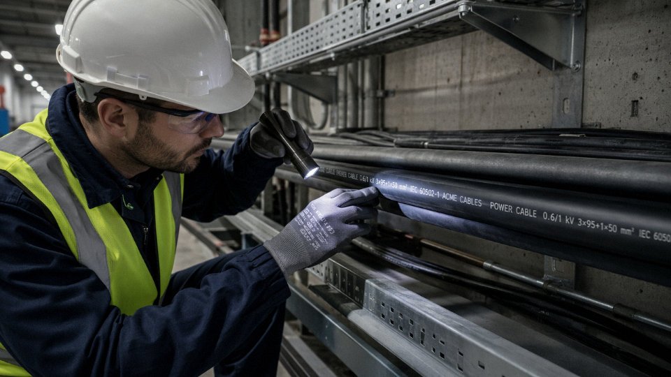
The jacket legend is the fastest diagnostic tool you have. Before you pull out a clamp meter or trace a conduit run, squat down and read what’s printed on the cable itself. Every legitimate power cable manufactured to IEC, UL, CSA, or GB standards carries a continuous printed or embossed legend that repeats every 200–500 mm along the jacket. If you know the sequence, you can identify conductor count, cross-section, voltage class, insulation system, and country of origin in under a minute.
The Standard Legend Sequence and What Each Field Tells You
A typical IEC-compliant jacket print runs in this order: manufacturer name or trademark, country of origin, trade designation or type code, voltage rating, conductor configuration and cross-section, governing standard, and year of manufacture. In practice you’ll see something like:
JINDA CABLE · CHINA · YJV22 · 0.6/1 kV · 3×95+1×50 mm² · IEC 60502-1 · 2023
Each field earns its place. The voltage rating — written as Uo/U, meaning phase-to-earth over phase-to-phase — tells you immediately whether this cable belongs in a 400 V distribution panel or a medium-voltage feeder. Don’t confuse 0.6/1 kV with 0.6 kV; the slash notation matters. The conductor configuration 3×95+1×50 mm² means three 95 mm² phase conductors plus a reduced 50 mm² neutral — a standard arrangement in European low-voltage distribution where the neutral carries less than full load. If you’re pulling that into a balanced three-phase system and someone swapped in a 4×95 mm² reel from a different project, you’ll still make it fit, but you’ve changed the neutral capacity and possibly violated the installation design. These things happen on busy sites.
Cracking the Type Designation String
Chinese GB-standard cables use alphanumeric codes that decode left-to-right. Take YJV22: Y = PVC outer sheath, J = XLPE (cross-linked polyethylene) insulation, V = PVC inner sheath, 22 = double steel-tape armor. Change one letter — say ZR-YJV22 — and the ZR prefix tells you it’s flame-retardant compound. NH- means fire-resistant (will maintain circuit integrity under flame for a defined period). These prefixes are not interchangeable, and substituting a flame-retardant cable where a fire-resistant one was specified is a compliance failure that won’t show up until the building inspector or an insurance assessor asks for the test certificates.
North American UL and CSA Markings
UL-listed cables carry designations like THHN, XHHW-2, or SOOW. Read them as stacked abbreviations: T = thermoplastic insulation, H = 75 °C rated, HH = 90 °C, N = nylon jacket, W = wet-location rated. XHHW-2 means cross-linked polyethylene insulation, 90 °C in both wet and dry locations — the “-2” suffix signals the wet-location 90 °C rating specifically. SOOW is a portable cord: S = hard service, OO = oil-resistant jacket and insulation, W = weather and water resistant. Plug the wrong cord type into a machine tool application and you’ll get insulation degradation from coolant exposure within months, not years.
European HAR and CENELEC Harmonized Codes
The H05RR-F or H07RN-F codes follow a defined CENELEC structure: H = harmonized (approved across member states), 05 or 07 = voltage class (300/500 V or 450/750 V), R = rubber insulation, N = polychloroprene or equivalent sheath, F = flexible stranding class. A cable marked with the HAR symbol — a stylized wavy line — plus a national suffix (e.g., ** VDE** for Germany, ** BASEC** for UK) has been tested by that national body against the harmonized standard. Without the HAR mark, European procurement teams can’t assume mutual recognition across borders.
Lot Numbers, Reel Lengths, and Reuse Risk
Sequential lot numbers and printed reel-length stamps — typically showing cumulative meters from the drum start — let you verify you’re working with original, unspliced cable. A length stamp that resets or jumps mid-drum is a red flag for spliced or recombined reels. On long infrastructure projects it’s worth photographing the legend at both drum ends before installation; if a warranty claim arises, the lot number is how the manufacturer traces back to the production batch, raw material certificates, and test records.
A cable with no visible jacket legend or with a legend that cannot be read is automatically non-compliant with IEC 60502-1.True
IEC 60502-1 Clause 8 mandates continuous jacket marking at defined intervals. A cable lacking readable identification fails this requirement regardless of its electrical performance and should not be installed in a compliant installation.
Faded, abraded, or completely absent legends on cable already in a plant usually indicate one of three things: the cable is old enough that the plasticizer migration has bleached the ink, it was stored in UV-exposed conditions, or — and this is worth taking seriously — it’s counterfeit or non-certified material that was never properly marked to begin with. In those cases, don’t assume continuity with a spec sheet. Pull a sample for cross-section verification with a micrometer, and if budget allows, send it for insulation resistance and conductor resistance testing before energizing anything.
Jinda’s Export Marking Practice
For export reels, Jinda prints dual-language legends (English plus destination-country language where required), dual IEC/GB certification references, and — on reels destined for markets that require full traceability — a QR code linking directly to the production batch record, third-party test certificates, and material declarations. In practice, procurement managers pulling cable on a multi-contractor site can scan the QR code to confirm the reel matches the approved submittal rather than relying on a paper certificate that may have followed a different drum.
Color Coding Systems by Region: IEC, NEC, AS/NZS, and Legacy Schemes
Color is usually the first thing an electrician or engineer looks at when picking up a cable. It’s also one of the most unreliable methods if you’re working across borders or in a building that’s been rewired in pieces over three decades. Understand the standards first, then verify with the jacket legend and a meter.
IEC 60446 and the Harmonized European / Asian Palette
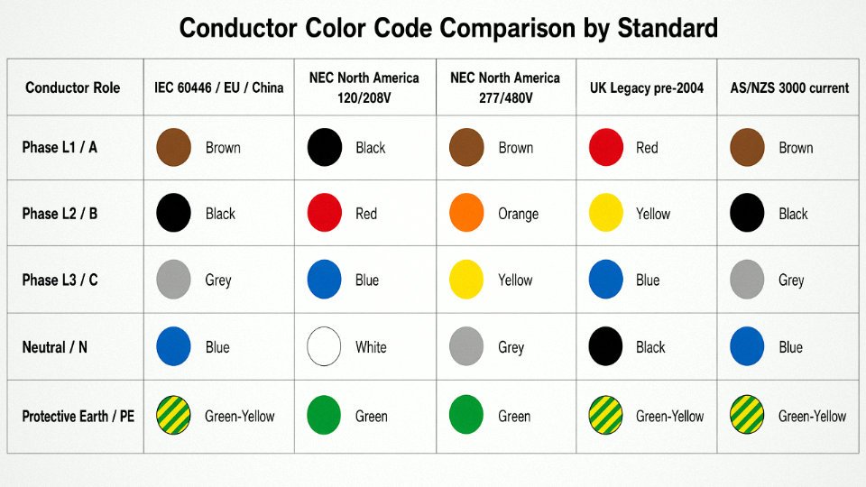
Under IEC 60446 (incorporated into HD 308 S2 and mirrored in China’s GB/T 6995), fixed wiring follows a consistent scheme: brown for L1, black for L2, grey for L3, blue for neutral, and the bicolor green-yellow stripe for protective earth. This palette is now effectively the default across the EU, most of mainland Asia, and a large chunk of South America. China’s domestic cables — including Jinda’s standard export range — ship with this scheme unless the customer specifies otherwise, and that’s worth knowing when you’re cross-referencing a Chinese-manufactured cable against a European panel drawing.
One practical note: some older IEC installations used black for all three phases and relied purely on sleeve markers or terminal numbering. You’ll still encounter this in industrial plant rooms built before roughly 2004. Don’t assume black equals L2 without checking the legend.
North American NEC Conventions
NEC doesn’t mandate phase colors the way IEC does — it mandates only what neutral and ground must look like. In practice, the industry has settled on black, red, and blue for phases A, B, and C in 120/208 V systems, and brown, orange, and yellow for 277/480 V three-phase. Neutral is white or grey; ground is green or bare copper. Flexible cords follow slightly different rules again.
The lack of a legally mandated phase-color sequence creates real problems on multi-contractor industrial sites. Two electricians from different shops can wire a 480 V panel with different phase-color conventions and both be technically compliant. Always verify phase rotation with a meter before making assumptions on NEC-wired equipment.
UK Legacy vs. Current BS 7671
Pre-2004 UK wiring used red for live, black for neutral, and green (or later green-yellow) for earth. That scheme is still live — literally — in a significant portion of existing commercial buildings. Since 2004, BS 7671 harmonized with IEC: brown for live, blue for neutral, green-yellow for earth. Any site that has been partially rewired is potentially running both systems in the same distribution board. This is a genuine shock risk, not a theoretical one.
Australian AS/NZS 3000
Australia and New Zealand used red for active, black for neutral, and green-yellow for earth for a long time. The 2018 revision to AS/NZS 3000 moved toward IEC harmonization — brown for active, blue for neutral — though older red-active wiring remains widespread in existing installations and isn’t required to be replaced. If you’re procuring cable for a greenfield Australian project today, confirm with the project spec whether the contractor wants the new or legacy scheme. Some contractors in Queensland, in my experience, still default to red-active out of habit.
Middle East and Africa: The Mixed-Heritage Problem
This region is genuinely difficult. Gulf Cooperation Council countries typically specify IEC-harmonized colors on paper, but sites often contain older British-scheme cables from the 1970s and 1980s alongside newer IEC cable from European or Asian suppliers. Sub-Saharan Africa shows similar layering, particularly in utility infrastructure. Project documentation — the cable schedule, the single-line diagram, the test certificates — is the only reliable cross-reference. Color alone will get you hurt.
Sheath and Jacket Colors as Cable-Type Signals
Beyond conductor insulation, outer jacket color carries its own meaning. Black general-purpose cable typically indicates UV-resistant PVC or PE for outdoor use. Orange sheathing signals mining or high-visibility industrial duty. Red outer jackets are conventionally reserved for fire alarm and suppression wiring in many jurisdictions, which is why you should never use a red-sheathed cable for general power runs on a project following that convention — the confusion in an emergency scenario is obvious. Blue LSZH outer jackets appear frequently in cold-store and food-processing environments where low-smoke, zero-halogen compounds are specified.
Conductor insulation color alone is sufficient to identify phase assignment on any power cable.False
Color coding varies by regional standard, installation era, and contractor practice. IEC, NEC, and legacy British schemes all differ, and the same color can mean different things in different contexts. Always cross-reference the jacket legend, project documentation, and test with a calibrated meter before making any phase assignment.
Multi-National Projects: Where Color Identification Breaks Down
A procurement manager sourcing cable for a plant expansion that involves a German main switchboard, Chinese-manufactured cable, and a local electrical contractor working to NEC conventions is looking at three different color vocabularies in the same building. This is not rare — it describes a large share of industrial projects in Southeast Asia and the Middle East right now. In that environment, color is a starting point, never a conclusion. Cross-check against the jacket print legend (the manufacturer, voltage rating, and standard are embossed on every reputable cable), the project cable schedule, and where there is any doubt, a phasing meter.
Jinda specifies conductor and jacket colors per the destination country standard on every export order. The color scheme is explicitly declared on the packing list and the third-party test certificate, so procurement and site teams are working from the same document — which matters more than people give it credit for when cables are being pulled eighteen months after the purchase order was placed.
Measuring and Classifying Conductor Cross-Section, Stranding, and Class
When the jacket print is worn off, the drum tag is missing, or you’re auditing a batch that arrived with questionable documentation, physical measurement is your fallback. It’s also, frankly, a good habit even when markings are present — counterfeit and mislabeled cable exists, and a 95 mm² cable that’s actually 88 mm² effective cross-section will run hot and fail early.
Metric vs. AWG/kcmil: Getting the Numbers to Match
Most of the world buys cable in metric cross-sections. North America uses AWG for smaller conductors and kcmil (thousand circular mils) for anything above roughly 107 mm². The two systems don’t map cleanly — there’s no AWG that lands exactly on 16 mm² or 50 mm² — so use the nearest equivalent and treat it as approximate.
| Metric (mm²) | Nearest AWG / kcmil | Typical ampacity at 90°C, copper, in conduit (A) | Ampacity depends on… |
|---|---|---|---|
| 1.5 | AWG 16 | 13–18 | ambient temp, conduit fill, insulation type |
| 2.5 | AWG 14 | 18–24 | same |
| 4 | AWG 12 | 25–32 | same |
| 6 | AWG 10 | 32–42 | same |
| 10 | AWG 8 | 44–57 | same |
| 16 | AWG 6 | 58–73 | same |
| 25 | AWG 4 | 76–95 | same |
| 35 | AWG 2 | 95–115 | same |
| 50 | AWG 1/0 | 120–145 | same |
| 70 | AWG 2/0–3/0 | 155–185 | same |
| 95 | AWG 3/0–4/0 | 190–225 | same |
| 120 | 250 kcmil | 220–260 | same |
| 185 | 350–400 kcmil | 285–330 | same |
| 240 | 500 kcmil | 340–390 | same |
| 300 | 600 kcmil | 385–440 | same |
| 400 | 750–800 kcmil | 440–500 | same |
| 630 | 1200–1250 kcmil | 570–650 | same |
Ampacity ranges above assume XLPE or EPR insulation, single-circuit, 30°C ambient. Trefoil burial, grouped conduit runs, or elevated ambient can pull those numbers down by 20–30%.
Measuring What You Actually Have
A calibrated digital micrometer or vernier caliper — 0.01 mm resolution minimum — is the right tool. Peel back the insulation on a sample length, separate the strands without stretching them, and measure the diameter of a single wire strand across at least five strands. Average those readings. Then count the total strand count and apply:
A = n × (π/4) × d²
where n is strand count and d is mean strand diameter in mm. If you get 91.2 mm² on a cable labeled 95 mm², that’s within IEC 60228 tolerance. If you get 83 mm², the cable is undersize and you have a supplier problem.
One practical note: don’t measure a strand that’s been kinked or nicked during stripping. Take your sample from a freshly cut end.
IEC 60228 Conductor Classes: Why They Matter More Than Just Size
The class designation tells you how the conductor is constructed, which directly affects flexibility, termination behavior, and long-term fatigue life.
Class 1 is solid wire. Cheap to manufacture, good for fixed in-wall installations, terrible if you try to flex it repeatedly or force it into a compression lug designed for stranded conductors. You’ll see it at 1.5–16 mm² mostly.
Class 2 is the standard stranded conductor for fixed wiring — the workhouse of industrial power distribution. A 95 mm² Class 2 cable will have somewhere around 19 strands, each roughly 2.5 mm diameter. It terminates cleanly in a standard lug and holds its shape in a cable tray.
Class 5 is fine-wire flexible, intended for trailing cables, machinery connections, and anywhere the cable moves. Same 95 mm² cross-section, but now you’re looking at 475–500 individual strands each around 0.51 mm diameter. It feels completely different in your hands — almost like a thick rope. It also wicks moisture into terminations if you’re not using the right ferrules, which is a maintenance headache that shows up two winters after installation.
Class 6 goes further still — extra-flexible, used in welding leads, portables, continuous-flex robotics applications. Strand diameters can drop below 0.2 mm. Under a loupe, it looks almost textile-like.
Two cables, same label, same rated current, completely different behavior. A Class 5 conductor in a fixed-lug terminal without a bootlace ferrule will cold-flow under torque and develop resistance over time. That’s how you get a warm termination block three years in.
Copper vs. Aluminum: Don’t Guess
Fresh copper is bright orange-pink. Aluminum is silver-grey and noticeably lighter — a 95 mm² aluminum conductor weighs roughly 40–45% less per meter than copper of the same cross-section. If you’re uncertain, the quick field test is a drop of white vinegar on a freshly filed surface: aluminum oxide dissolves and you’ll see fizzing within 30–60 seconds. Copper doesn’t react.
Operational warning: Aluminum conductors require anti-oxidant compound at every termination and aluminum-rated lugs. Skipping this causes galvanic oxidation at the contact surface, rising resistance, and eventual thermal failure at the joint — often months after commissioning when nobody connects it to the installation.
CCA: The Problem That Doesn’t Announce Itself
Copper-clad aluminum looks like copper on the outside. File through the conductor surface — literally two or three strokes with a fine file — and check the cross-section under good lighting. CCA shows a distinct silver-grey core surrounded by a thin copper shell. Weight is also a giveaway: CCA runs about 60–65% of the mass of pure copper for the same geometry.
CCA conductors are acceptable substitutes for solid copper in high-current industrial terminationsFalse
CCA has higher resistivity than copper, lower ampacity per cross-section, and the aluminum core creates differential thermal expansion at terminations. In high-current applications this leads to connection loosening, arcing, and fire risk. IEC and most industrial standards do not recognize CCA as equivalent to copper for power distribution conductors.
CCA turns up in budget cable imported through distributors who aren’t tracking raw material sourcing. The per-kilogram cost difference versus electrolytic copper makes adulteration economically tempting. Third-party verification on incoming reels is not paranoid — it’s procurement hygiene.
Armoring: Physical and Magnetic Identification
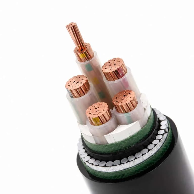
Run a magnet along the armor layer. Steel wire armor (SWA) and steel tape armor (STA, sometimes marked /22 in IEC notation) are magnetic. Aluminum wire armor (AWA) is not. Flat wire armor (FWA) looks geometrically different from round wire armor — the wires are rectangular in cross-section, visible where the outer sheath is cut back, and are typically used on oval or multicore flat cables where round wire would create mechanical imbalance.
SWA is the standard for direct-burial and mechanical-protection applications. AWA is specified where magnetic interference is a concern or where the cable serves single-core applications — steel armor on a single-core AC cable would create eddy current losses and heating.
Jinda conductors are manufactured from electrolytic copper meeting IEC 60228 Class 2 and Class 5 requirements, with strand resistance verified by third-party testing per reel before shipmentTrue
Electrolytic copper (≥99.9% purity) is the correct raw material for IEC 60228-compliant conductors. Per-reel resistance testing at the point of manufacture — rather than just batch sampling — allows rejection of individual reels that fall outside resistance tolerance, providing traceability that matters in project-critical procurement.
Insulation and Sheath Material Identification: PVC, XLPE, EPR, LSZH, and More
Knowing a cable’s voltage rating and conductor size gets you halfway to a correct specification. The other half is the polymer. Put the wrong sheath material into a tunnel, a ship’s cable trunk, or a food-processing washdown area and you will eventually face either a fire-safety non-compliance flag or an accelerated failure you can’t immediately explain. The identification methods below range from reading the jacket print to a controlled burn — each with real limitations you need to understand.
PVC — The Default You’ll Encounter Most Often
Polyvinyl chloride covers probably 60–70% of the general wiring you’ll handle in industrial and commercial settings. It’s smooth, slightly glossy, and ranges from a creamy off-white on older stock to jet black on modern UV-stabilised grades. Cut it with a knife and there’s a faint, slightly acrid chemical smell — mild on fresh material, stronger on heat-aged cable pulled from a machine that’s been running hot for years. Standard PVC is rated 70°C continuous conductor temperature; the heat-resistant HR grade pushes to 90°C and is noticeably stiffer at room temperature. In IEC type designation strings, look for the letter V (e.g., NYY, NYM). One practical warning: PVC gets brittle below roughly -15°C to -20°C depending on formulation, so outdoor installations in northern climates that spec standard PVC often see jacket cracking at conduit entry points after the first hard winter.
XLPE — Stiffer, Waxy, and Built for Higher Stress
Cross-linked polyethylene is easy to distinguish by feel. It’s noticeably harder and waxier than PVC at the same cross-section, and it doesn’t have PVC’s slight chemical odour. Colour is typically white or black. The cross-linking process means it won’t melt and flow under fault conditions — short-circuit rating reaches around 250°C, continuous rating is 90°C, which is why it’s the standard insulation for 0.6/1 kV distribution cables and virtually all medium-voltage cables from 3.6/6 kV upward. In designation strings it appears as X or 2X (for XLPE sheath variants) or J in some European coding systems. If you’re measuring apparent hardness with a fingernail scratch test, XLPE leaves a faint waxy mark rather than a groove; PVC deforms more visibly.
EPR — The Flexible Performer in Harsh Environments
Ethylene propylene rubber has a distinctly rubbery feel — it compresses and springs back rather than holding a deformation the way PVC does. Most EPR-insulated cables you’ll see are red-brown, dark grey, or black. The material retains useful flexibility down to around -40°C, which is why it dominates marine cables, mining trailing cables, and any portable application where the cable gets repeatedly flexed in cold conditions. Continuous rating is 90°C, similar to XLPE, but the mechanical resilience is in a different league for dynamic applications.
LSZH — Mandatory in Confined Spaces, Easy to Misidentify
Low smoke zero halogen (also written LS0H or LSOH depending on the standard body) looks superficially similar to PVC — usually matte grey or black. The critical difference shows up in two ways. First, scratch the surface and bring it close to your nose: LSZH has essentially no chemical smell, whereas PVC has that faint chlorine-adjacent odour. Second, the burn test: hold a small off-cut in a flame, then remove it. PVC produces dense black smoke and, if you hold pH paper or a damp litmus strip in the smoke, it will turn acidic from hydrogen chloride gas. LSZH produces thin, whitish smoke with no acid response.
LSZH cable produces significantly less smoke and no halogen acid gases compared to PVC when exposed to fire, as verified under IEC 61034-2 (smoke density) and EN 50267 (halogen content) test protocols.True
IEC 61034-2 measures light transmittance through smoke from burning cables; EN 50267 / IEC 60754 measures halogenated combustion products. LSZH compounds are specifically formulated with aluminium trihydrate or magnesium hydroxide fillers that suppress both flame spread and acid gas generation, a well-documented and independently testable property.
LSZH is mandated — not just recommended — in rail tunnels, road tunnels, subway stations, passenger ships, and densely cabled public buildings in most jurisdictions that adopt IEC or EN standards. Routing standard PVC in those locations is a compliance failure waiting to surface during a fire-safety audit.
Silicone Rubber — High Temperature and Unusual Flexibility
You won’t see silicone cable often on a standard plant floor, but when you do it’s unmistakable: translucent or bright red, almost gel-like in flexibility, and it holds its pliability regardless of ambient temperature. Continuous rating is around 150–180°C depending on formulation, with some specialist grades going higher. It’s used for furnace door wiring, kiln thermocouples, and aerospace ground support equipment. Cost is substantially higher than any of the above — typically 3x to 5x equivalent PVC cross-sections depending on market conditions — so substituting it unnecessarily is a procurement error worth catching early.
Field Tests Worth Doing (and Their Limits)
The copper wire burn test for halogens is simple: strip a small piece of insulation, hold it on a copper wire, and bring it into a clean propane flame. A green-tinged flame indicates halogen compounds (chlorine, fluorine) volatilising off the copper. PVC will do this reliably. LSZH will not. This is a screening test, not a certification method — it won’t distinguish between chlorine and fluorine, and some flame retardant additives can produce misleading results.
Water flotation is useful when you have unlabelled material scraps: XLPE and PE float (density around 0.92–0.95 g/cm³); PVC and most LSZH compounds sink (density typically 1.3–1.7 g/cm³ depending on filler loading). EPR and silicone sit somewhere in between and are less reliable with this test.
Cold hardness comparison at -20°C — if you have a freezer on site — will quickly separate PVC (stiff, risks cracking) from EPR and silicone (still flexible).
Jacket Flame and Fire Performance Markings
Flame performance isn’t inherent to insulation type alone; it depends on the specific compound formulation and is verified by test. Look for these IEC designations printed on the jacket or in the cable datasheet:
| Marking | Standard | What It Tests |
|---|---|---|
| IEC 60332-1 | Single cable vertical flame | Minimum baseline; flame doesn’t propagate vertically |
| IEC 60332-3 Cat. C or B | Bunched cable vertical flame | Bundled installation; Cat. B is more demanding than Cat. C |
| IEC 60331 | Circuit integrity under fire | Cable maintains electrical function for 30–120 min at defined temperatures |
| IEC 61034-2 | Smoke density | Light transmittance ≥60% — critical for evacuation visibility |
A cable can carry an LSZH compound and still fail IEC 60332-3 if the installation is dense and the compound isn’t formulated for that category. Always verify the specific test category against your routing design, not just the generic “LSZH” label.
Jinda’s standard range covers PVC (70°C and 90°C HR grades), XLPE, LSZH, and EPR insulation and sheath options across low and medium voltage constructions, with independent lab material test certificates available for procurement packages requiring documented flame performance and halogen content verification.
Voltage Rating and Application Class: Matching Cable to Circuit Without Guesswork
The voltage rating stamped on a cable jacket is not a single number — it is a ratio, and misreading it is one of the more common procurement errors I see on medium-voltage projects. Getting it wrong means either under-rated cable in service (insulation degradation, partial discharge, eventual failure) or expensive over-specification that adds cost with no benefit.
Understanding the Uo/U Designation
IEC notation expresses voltage rating as Uo/U, where Uo is the conductor-to-earth (phase-to-ground) voltage and U is the conductor-to-conductor (phase-to-phase) voltage. A cable marked 0.6/1 kV is rated for 600 V phase-to-ground and 1,000 V phase-to-phase. There is also Um — maximum system voltage — which represents the highest voltage the cable can tolerate under transient or switching conditions; for 0.6/1 kV cable, Um is typically 1.2 kV. This distinction matters on systems with poor voltage regulation or frequent switching transients.
A 300/500 V cable is only suitable for flexible cords, light fittings, and domestic appliances. Put it on a 400 V three-phase industrial distribution panel and you are operating at or above Uo on a normal cycle — not a margin anyone should accept.
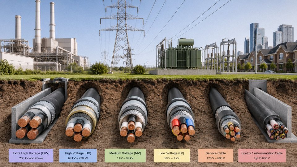
Voltage Tiers and Where They Actually Appear
The tiered system maps fairly cleanly to application type, though there is overlap in the middle:
| Uo/U Rating | Typical Application | Notes |
|---|---|---|
| 300/500 V | Flexible cords, luminaires, office equipment | Not for fixed industrial wiring |
| 0.6/1 kV | Building distribution, motor feeders, industrial panels | The most common factory cable |
| 3.6/6 kV – 6/10 kV | MV switchgear feeds, substations up to 11 kV | Requires semi-con screens |
| 8.7/15 kV – 18/30 kV | Medium-voltage distribution, 22–33 kV systems | Thicker insulation, larger bend radius |
| 64/110 kV and above | Transmission, grid interconnection | Specialist installation; factory testing mandatory |
When the Jacket Legend Is Worn or Absent
On older installed cable — and this situation is more common than anyone admits, especially in plants that have been running since the 1980s or 90s — the printed legend may be abraded or paint-coated. In that case, insulation wall thickness measured against IEC 60502 tables gives you a rough cross-check. For XLPE-insulated 0.6/1 kV cable, minimum insulation thickness runs from about 0.7 mm on 1.5 mm² conductors up to roughly 2.8 mm on 300 mm². A 6/10 kV cable will have significantly thicker insulation — typically 3.4 mm and up for the same conductor sizes — plus the semi-conductive screens described below. Use a calibrated micrometer at a cut end; measuring through the jacket tells you nothing useful.
Semi-Conductive Screens as a Voltage Indicator
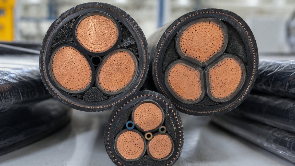
This is the most reliable visual marker of medium-voltage cable that most plant engineers don’t think about until they’ve already made a mistake. MV cables carry an inner semi-con layer over the conductor and an outer semi-con layer beneath the metallic screen. These layers — usually a dull black, slightly rough-textured material — are not present on low-voltage cable at all. If you see them, the cable is MV-grade. If you don’t, assume LV only, regardless of what someone tells you about the “big conductor size.”
Application-Class Suffixes
Both IEC type codes and Chinese GB designations append suffixes to indicate environmental suitability. Common ones worth knowing: -WP for weatherproof (UV-stabilised outer sheath), -FR for fire-resistant cores, -B for direct burial, -P for petroleum or chemical exposure (usually an oil-resistant outer sheath, not just standard PVC), and -M for mining-grade cable with additional mechanical and flame protection. These suffixes define the application envelope, not just the voltage rating. A 0.6/1 kV cable without -B buried directly in clay soil will not last — sheath damage from soil chemistry and mechanical stress begins within a few years in most climates.
Control Cable Substitution: A Specific Warning
Control cables like KVVP or KYJV look similar to power cables, especially in small cross-sections. Multi-core, screened, neatly jacketed — from a meter away it is an easy mix-up. Control cables are engineered for signal transmission and low-power switching circuits, not load-carrying duty. Running a 5 A motor control circuit through KYJV 1.5 mm² is fine. Feeding a 15 kW motor starter through the same cable is not fine, regardless of conductor count or voltage class printed on the jacket.
Derating: Rated Voltage Is Not the Only Number That Matters
A cable’s voltage class tells you whether the insulation can handle the electric field. Whether the conductor can handle the current at that location is a separate, equally important question. A 630 mm² 0.6/1 kV cable has a free-air rating in the range of 800–1,000 A depending on conductor material and ambient temperature. Buried in a tight three-cable duct bank with soil thermal resistivity around 2.5 K·m/W — not unusual in dry clay — that same cable may safely carry only 60–70% of that figure. Grouping factors for cables bunched in trays or conduit can reduce ratings further still, sometimes down to 50% in dense installations.
Jinda's 1–35 kV XLPE cables manufactured per IEC 60502-2 and GB/T 12706 are shipped with individual partial discharge test records.True
Partial discharge testing is a standard factory acceptance test for medium-voltage XLPE cables under IEC 60502-2; individual test records per drum are routine practice for compliant MV cable manufacturers and allow buyers to verify insulation integrity before installation.
Partial discharge records matter particularly for MV cable because PD is the mechanism that slowly destroys XLPE insulation at operating voltage — and the damage is cumulative and invisible from the outside until failure occurs.
Electrical Test Methods to Confirm Cable Identity When Visual Clues Are Insufficient
Visual inspection gets you most of the way there — until it doesn’t. Worn jacket print, field-cut reels with no drum label, suspect imported stock, or cables pulled from a decommissioned plant: any of these situations puts you in front of a conductor you can’t fully trust. At that point, electrical testing is the only objective path forward.
Insulation Resistance Testing
Start here. A 500 V megohmmeter is sufficient for cables rated up to 0.6/1 kV; use 1,000 V for anything in the medium-voltage range. Per IEC 60364-6, the minimum acceptable insulation resistance for a healthy low-voltage circuit is 1 MΩ, though in practice a new or recently manufactured cable in dry conditions should read well above that — typically 100 MΩ to several GΩ depending on length and insulation type. A reading that just scrapes past 1 MΩ on a short run isn’t a pass you should feel comfortable with; it suggests moisture ingress, insulation degradation, or a polymer that’s aged out. XLPE insulation tends to hold significantly higher IR values than PVC under equivalent conditions, so a suspiciously low reading on what’s claimed to be XLPE cable is a red flag worth chasing.
Test between each conductor and earth, and between conductors. Both measurements matter. Conductor-to-conductor leakage that doesn’t appear in a simple earth test has caused more than a few nuisance trips on distribution boards.
DC High-Potential (Hipot) Testing
Where IR testing checks condition, a hipot test probes the margin. Apply 3.5 kV DC for 0.6/1 kV-rated cables, and roughly 15 kV DC for 3.6/6 kV class — these levels are derived from IEC 60502 type-test requirements scaled for field use. A clean pass with no current runaway or breakdown confirms the insulation wall is both present and sufficiently thick. If current climbs steadily during the hold period rather than stabilizing, that’s a classic sign of a compromised or undersized insulation wall — exactly what you’d see with counterfeit or downrated cable passed off at a higher voltage class.
A cable that passes an insulation resistance test will automatically pass a hipot testFalse
IR testing uses low voltage and measures bulk resistance; a hipot test applies a much higher stress voltage that can reveal localized weak spots, pinholes, or thin insulation walls that an IR test simply doesn't excite enough to expose.
Conductor Resistance per IEC 60228
This is the cleanest way to confirm both conductor cross-section and material. Measure DC resistance at — or corrected to — 20°C and compare against the IEC 60228 table. A 1.5 mm² copper conductor should read no more than 12.1 Ω/km; 95 mm² copper should come in at or below 0.193 Ω/km. If your measured value runs 40–60% higher than the copper standard for the claimed size, you’re almost certainly looking at copper-clad aluminum (CCA), which matters enormously for termination torque, connector compatibility, and ampacity calculations. This single test has caught more substitution fraud in procurement than any visual check.
Continuity and Phase Tracing
A basic low-voltage buzzer kit or a digital multimeter in continuity mode lets you trace individual cores through a multicore cable and confirm the actual core count and pairing. It sounds obvious, but on a 7-core or 12-core cable pulled off an unlabeled reel, verifying that the core count and color sequence match what the job spec calls for takes maybe ten minutes and prevents wiring errors that can take days to trace afterward.
Time-Domain Reflectometry
TDR is underused in plant maintenance and procurement inspection alike. You inject a fast pulse into the conductor and analyze the reflected waveform. The propagation velocity — which varies by insulation geometry and dielectric constant, typically 0.55–0.85 times the speed of light depending on insulation type — lets you estimate cable length on an unmarked drum reel. Impedance discontinuities in the trace reveal joints, damaged sections, or transitions between cable types spliced mid-run. For an unknown cable of uncertain origin, TDR gives you a fingerprint of the cable’s geometry that cross-references against known cable types reasonably well.
Capacitance per Meter as an Insulation Geometry Check
XLPE cables typically show capacitance in the range of 0.1–0.4 µF/km; PVC-insulated cables at comparable voltage ratings tend to run 0.2–0.6 µF/km. Overlap exists, so this isn’t a definitive material identification on its own, but a capacitance value that falls well outside the expected range for the claimed insulation type is worth flagging before you proceed.
Safety Protocol Before Any Test on an Unknown Cable
Lockout/tagout every circuit the cable connects to or might connect to — on both ends. Discharge the cable between tests using an appropriate discharge resistor; capacitive charge on medium-voltage cables is not trivial. PPE selection should reflect the arc flash category appropriate to the highest voltage class the cable might be rated for, not what you hope it is. This is not the place for shortcuts.
When Visual and Field Testing Aren’t Enough
Some situations genuinely require laboratory work. XRF analysis identifies conductor alloy composition and can confirm whether the copper content meets IEC 60228 Class 1 or 2 requirements. Differential scanning calorimetry (DSC) distinguishes polymer types when burn behavior is inconclusive — relevant for fire-safety compliance and LSZH verification. If you’re qualifying a new supply source or working through a dispute over material specification, Jinda’s technical team can coordinate access to accredited laboratory testing on project samples, which is the only answer that holds up in a contractual or regulatory context.
Identifying Specialty and Hazardous-Location Cables: Mining, Marine, Fire-Resistant, and EV
These cable types are where substitution errors stop being paperwork problems and start causing fires, fatalities, or regulatory shutdowns. Visually, a mining trailing cable and a standard armored power cable can look almost identical to someone who isn’t expecting the difference. The outer sheath color, the jacket markings, and the internal construction details are what separate them — and getting it wrong in a coal mine or on a vessel isn’t recoverable.
Mining Cables
Mining cables built to IEC 60502-1 Type MC or Chinese standard MT 818 carry a distinctly heavy rubber or polychloroprene (PCP) outer sheath — typically 4–6 mm thick on trailing types, noticeably heavier and more pliable than the PVC jacket on a standard SWA cable. The outer sheath is almost always orange or black, and the jacket legend will include “MINING,” “MSHA” (in North American markets), or explicit MT/IEC type designations. Round wire armor runs continuously around the cable rather than being flat or tape-style. What makes these cables operationally different isn’t just the sheath toughness — it’s the earth continuity conductors (ECCs) and pilot cores. The ECCs are sized to trip protective relays fast enough to cut power before a fault arc develops in a flammable atmosphere. Pull back the outer sheath on any genuine mining cable and you’ll find those dedicated earth wires laid concentrically, often with their own color coding separate from the main phase insulation. Substitute a standard flex here and you’ve removed the only thing standing between a fault and a methane ignition.
Marine Shipboard Cables
IEC 60092-350 governs shipboard cable construction, and approval by a class society — Lloyd’s Register, Bureau Veritas, DNV, ABS — is the non-negotiable identifier. Look for the class society abbreviation stamped directly on the jacket, usually every 500 mm or so. Conductors are tinned copper; bare copper corrodes aggressively in salt-laden environments within months. Insulation is typically flame-retardant EPR or XLPE, and even cables that appear flat in cross-section (to fit in cable trays) will have a circular conductor arrangement internally. The flame-retardant performance requirements under IEC 60332-3 are stricter than most land-based industrial cables. If the jacket doesn’t carry a class society stamp and a clear IEC 60092 type designation, don’t install it on a vessel.
Fire-Resistant Cables
Genuine fire-resistant cables per IEC 60331 or BS 6387 Category CWZ maintain circuit integrity at 750°C for 3 hours minimum; CWZ-rated product adds water spray and mechanical shock to that same fire exposure. The functional mechanism is a mica tape layer wound directly over the conductor insulation — mica holds its dielectric properties at temperatures that incinerate PVC or XLPE completely. Outer sheath is LSZH, usually brick-red or red, and the jacket print will carry “FR,” “FP,” “CWZ,” or the explicit IEC 60331 reference.
A cable labeled LSZH or LSOH provides fire-resistant circuit integrity equivalent to IEC 60331.False
LSZH describes low smoke and halogen-free emission behavior during combustion, not circuit integrity under sustained fire. A genuine fire-resistant cable requires a mica tape barrier layer and must pass IEC 60331 or BS 6387 survival tests. LSZH sheathing alone does not confer circuit integrity.
EV Charging Cables
IEC 62893 charging cables are harder to fake-identify because they physically resemble heavy flexible cord. The mandatory identifier for high-voltage EV circuits under IEC 60445 is orange outer sheath — this isn’t a convention, it’s a requirement. Internally, a compliant EV charging cable carries not just power conductors but a pilot conductor (CP) and a proximity conductor (PP), both of which are active components in the charging communication protocol. Stripping those out or substituting a standard rubber flex cord creates a cable that connects physically but fails functionally — the vehicle won’t authenticate the charge session, or worse, won’t detect a disconnection event correctly. TPU outer sheaths are common on portable EV cables because TPU resists both UV degradation and the repeated mechanical flexing of daily plug-in cycles significantly better than standard PVC.
PV Solar Cables
Single-core, UV-resistant, rated 1.5 kV DC — PV cables per IEC 62930 or EN 50618 look deceptively simple. The cross-linked XLPE (or LSZH-XLPE on some specs) insulation is the core differentiator. Standard 0.6/1 kV building wire is not rated for DC voltage at that level, not UV-stabilized for 25-year outdoor exposure, and not tested for the double-insulation construction that PV strings require. The TÜV Rheinland or UL 4703 mark on the jacket is what you’re looking for; without it, you have no verified evidence the cable passed the aging, UV, and DC voltage tests the standard requires. Color is typically black for negative and red for positive, though some markets use both conductors in black with polarity marked at termination.
Instrumentation and Thermocouple Extension Cables
These get confused with control cable constantly, and the consequences are subtle but real. Thermocouple extension cables use conductor alloys matched to the specific thermocouple type — Type K uses Chromel/Alumel conductors, Type J uses iron/constantan, and so on. The letter designation is printed on the jacket (K, J, T, E, N). Substituting a copper control cable pair into a thermocouple circuit introduces a junction error that shifts temperature readings by anywhere from a few degrees to tens of degrees, depending on ambient temperature. In a kiln or furnace control loop, that kind of offset causes either product scrap or overtemperature damage. The foil or braid shield, small gauge (typically 0.5–1.5 mm² per pair), and the type letter on the jacket are the visual identifiers.
Requesting Specialty Cable Certificates
For hazardous-location projects, visual identification alone isn’t sufficient for procurement sign-off. Demand the full documentation set: the type test report showing which specific IEC or national standard was tested, the routine test report for the production batch being shipped, a third-party audit certificate (SGS, Intertek, TÜV, or equivalent), and a RoHS/REACH material declaration if the cable is entering EU or UK supply chains. For mining or marine applications, the class society approval certificate or MSHA acceptance number needs to be on file before the cable goes into a hazardous area.
Jinda structures export documentation packages for hazardous-location projects with all of these components included as standard, not as add-ons, because customs authorities in several markets — particularly EU, Australia, and the Gulf states — will hold shipments that arrive without traceable test documentation regardless of how the cable looks physically.
Building a Permanent Cable Identification System for Large Installations and Bulk Procurement
A cable identification system that lives only in someone’s head — or in a spreadsheet on a single engineer’s laptop — will fail. Staff leave, hard drives die, and three years after commissioning, the maintenance crew is standing in front of a cable tray with no reliable way to know what anything carries. Getting this right at the start costs far less than unraveling it later.
Developing a Cable Schedule That Actually Gets Used
The cable schedule is the foundation. Every entry should carry, at minimum: a unique cable tag number, the from/to endpoints (panel ID and terminal reference, not just room names), system voltage, conductor cross-section and number of cores, insulation and sheath type, routing path referenced to a drawing number, installation date, post-installation test results (insulation resistance, continuity, HV proof test voltage), and the manufacturer’s reel or drum number. That last field matters more than most people realize — it ties a specific cable run back to a mill certificate and a test report, which becomes essential if you ever need to make a warranty claim or trace a batch defect across an installation.
In practice, I’ve seen schedules that omit the drum number entirely and then can’t confirm whether a particular run was from the compliant batch or the one that failed QC. Don’t leave that field optional.
Physical Tagging: Choosing by Environment, Not by Price
For indoor dry environments, UV-resistant nylon cable markers conforming to IEC 62491 are generally fine. Outdoor, underground, or wet-process areas are a different story — embossed aluminum strip tags resist UV, standing water, and most industrial cleaning chemicals far better than printed labels, which go illegible within a couple of seasons in direct sun or chemical splash zones. Heat-shrink label sleeves offer a reasonable middle ground for moderate-exposure locations, and they’re fast to apply during termination.
The selection criteria to specify: operating temperature range, IP rating of the environment, chemical exposure class, and expected service life before the next inspection window. A tag that’s rated for 85 °C continuous but installed next to a steam pipe running 110 °C will fail — and finding out during a fault investigation is an expensive way to learn that.
Phase Identification at Terminations
Single-core medium-voltage cables often arrive with a black or natural-colored outer sheath — no color distinction between phases at all. The standard approach is heat-shrink color sleeves applied at each termination end, matched to the regional color code (brown/black/grey for L1/L2/L3 in IEC installations). This isn’t optional cosmetics; it’s the only phase identification that exists on those cables. Skipping it, or applying the wrong colors, creates a misidentification risk every time someone opens that switchgear panel for the next 30 years.
Digital Asset Management: QR Codes and RFID
Linking a physical tag to a CMMS or BIM model via QR code is now straightforward and reasonably cheap. On oil and gas platforms and large data centers, RFID transponders embedded in cable tie mounts allow asset scanning without direct line-of-sight, which matters in congested cable trays. The critical discipline is keeping the digital record synchronized with physical changes — a cable that gets re-routed during a modification but whose CMMS entry still shows the original path is worse than no record, because it actively misleads.
QR-code cable tags linked to digital test certificates can significantly reduce fault-finding time during maintenance.True
Asset management studies and maintenance engineering literature consistently show that rapid access to as-built documentation reduces diagnostic time, though actual savings vary widely by installation complexity and staff familiarity with the system.
Re-Identifying Legacy Cables in Brownfield Upgrades
This is where shortcuts cause incidents. Before any legacy cable gets integrated into a new control system, the procedure should be: establish safe isolation, apply temporary lockout/tagout, perform insulation resistance testing (typically 500 V DC for LV cables, 1 kV or 2.5 kV DC for MV — confirm against the cable’s rated voltage), apply IR thermography under load if the circuit can be briefly energized safely, and only then assign a new tag and enter the cable into the updated schedule. Skipping the IR test because the cable “looks fine” is a common shortcut in brownfield projects with tight commissioning deadlines. It’s also how a degraded cable splice inside a conduit ends up causing a fault six months after handover.
Procurement Documentation and Jinda’s Supply Package
For bulk cable orders, documentation quality from the manufacturer directly affects how clean your installation records can be. Jinda’s standard supply package includes drum labels with QR codes linking to batch test certificates, jacket surface marking at 10 m intervals for footage traceability, and a packing list cross-referenced to purchase order line items — so each drum can be matched to a specific project schedule row before it even leaves the warehouse. For projects above roughly 50 km of cable, Jinda’s factory technical team is available to review the cable schedule, assist with drum allocation planning to minimize joins within runs, and configure project-specific labeling to match the installation contractor’s tagging convention.
On labeling durability: IEC 62491 specifies test criteria covering legibility after heat aging, UV exposure, chemical immersion, and mechanical abrasion. When ordering pre-tagged cable from any supplier, specify the standard explicitly and ask for test evidence — not just a declaration. The difference between a tag that passes IEC 62491 and one that merely looks similar is about five years of outdoor service life, give or take.
Frequently Asked Questions About Power Cable Identification
How do I identify a power cable with no visible markings at all?
Start with conductor resistance. Measure DC resistance per IEC 60228 using a micro-ohmmeter or a Kelvin bridge, then compare your result against the standard table values — a 10 mm² copper conductor at 20 °C should read around 1.83 mΩ/m, give or take a small tolerance depending on stranding class. From there, measure insulation wall thickness with a calibrated digital micrometer on a freshly cut cross-section; IEC 60502-1 specifies minimum values for each cross-section and voltage tier, so you can work backwards. IR testing at 500 V DC (for cables up to 1 kV) or 1 kV DC (for MV cables) won’t confirm conductor size, but it will tell you whether the insulation is sound and give you a rough sense of dielectric quality consistent with a particular material type. Between resistance, wall thickness, and IR value, you can usually narrow down cross-section, voltage class, and insulation type to two or three candidates without any jacket print at all.
What’s the visual difference between a power cable and a control cable?
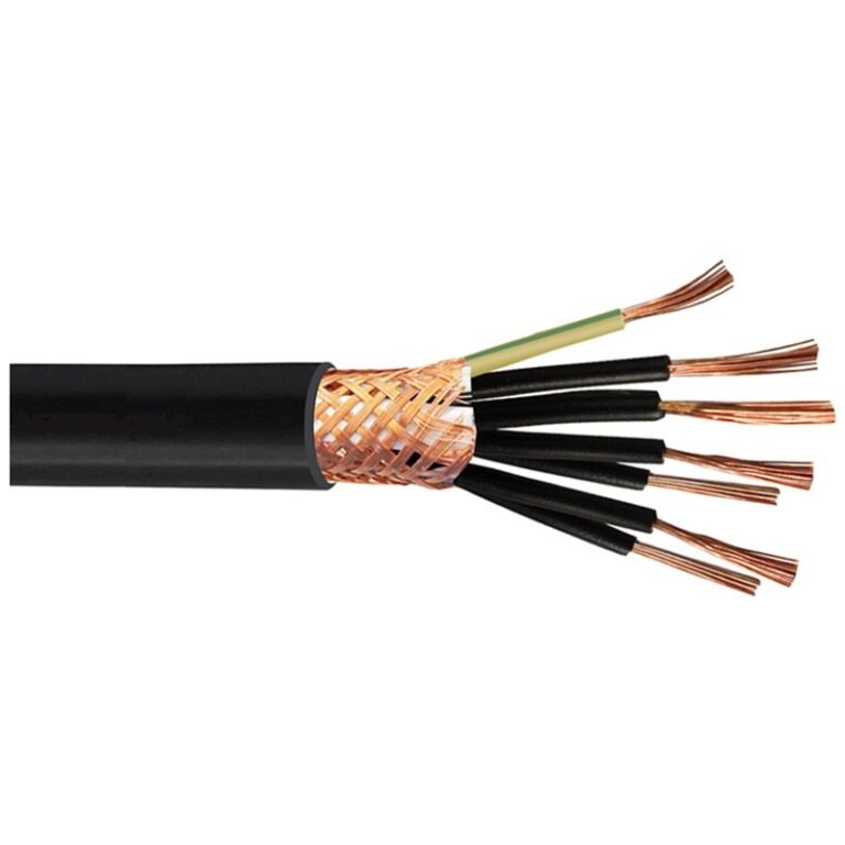
Power cables carry fewer conductors at larger cross-sections — typically 1 to 5 cores at 2.5 mm² and above, often up to 300 mm² or more for distribution feeders. Control cables run more cores (sometimes 12, 24, or even 48 pairs) at small sections, usually 0.5 mm² to 2.5 mm², and almost always include an overall copper braid or foil screen. In Chinese national standards, the type code makes this explicit: KVV or KVVP prefixes denote control cables; YJV or VV denotes power. If you’re looking at an unmarked cable in a panel, the sheer number of small cores screams control; a fat, stiff, three-core cable with chunky conductors is almost certainly power. Don’t confuse instrumentation cables (shielded, twisted pairs) with control cables — they’re thinner still and usually have individual pair screening.
How do I know if a cable is rated for direct burial?
Look for mechanical armoring — steel wire armoring (SWA), steel tape armoring (STA), or aluminum wire armoring (AWA) — plus a polyethylene (PE) outer sheath over that armoring. A PVC outer sheath alone is generally not considered suitable for direct burial in aggressive soils. IEC 60502-1 and -2 specify minimum sheath thicknesses for buried service; if your measured outer sheath is thinner than the standard minimum for that diameter, treat it as not burial-rated regardless of what anyone tells you. Some regional standards use suffix codes like -B or -WB in the cable designation. When in doubt, ask for the test report — a genuine direct-burial cable will have documentation covering crush and impact resistance.
Is it safe to rely on color coding alone to identify live conductors?
No. Color coding is a starting point, not a safety guarantee. Colors fade, installations get modified by people who ignored the standard, and older cables in many plants pre-date modern IEC harmonization — meaning brown may have been used as neutral in a previous wiring era in some European countries. Always use a non-contact voltage tester before touching any conductor, and cross-reference against as-built drawings. In practice, I’ve seen grey conductors used as phase in retrofitted panels because someone ran out of brown. The drawing said one thing; the wire said another.
Color coding alone can safely identify live versus neutral conductorsFalse
Color coding follows standards but is not physically enforced; incorrect wiring, modifications, and legacy installations make visual color identification unreliable without instrument verification.
How do I tell copper from aluminum conductors without any tools?
Aluminum is noticeably lighter — density around 2.7 g/cm³ versus roughly 8.9 g/cm³ for copper, so a large aluminum cable feels almost surprisingly light for its diameter. Cut the end cleanly with side cutters and look at the freshly exposed face: aluminum shows a silver-grey surface that quickly develops a dull white chalky oxide layer within a minute or two. Copper shows a warm reddish-orange on a fresh cut, darkening to brown as it oxidizes. In a cable tray, aluminum conductors also tend to be a larger physical diameter for the same current rating, since aluminum conductors need to be roughly 1.5 to 1.6 cross-section steps up from copper to carry equivalent current. A 70 mm² aluminum cable where you’d expect 50 mm² copper is a dead giveaway.
What does the voltage rating on the jacket actually mean for my system?
The rating is expressed as Uo/U — for example, 0.6/1 kV. Uo is the rated voltage from any conductor to earth (or the metallic screen); U is the rated voltage between any two phase conductors. Your system’s phase-to-earth voltage must not exceed Uo, and your line-to-line voltage must not exceed U. On a 400 V three-phase system, phase-to-earth is around 230 V and line-to-line is 400 V, so a 0.6/1 kV cable fits with margin to spare. Where people get into trouble is on ungrounded or high-impedance earthed networks, where phase-to-earth voltage under a single-fault condition can briefly approach full line voltage — that’s when the Uo rating really earns its keep.
Can I use a medium-voltage cable at low voltage just to get more current capacity?
Technically the insulation won’t fail, but this is a bad idea operationally. MV cables are built with semi-conductive conductor screens and insulation screens, and their capacitance per unit length is designed around MV field grading — running them at LV can cause unexpected charging currents, interference with protection relays, and compatibility problems with variable-frequency drives. More practically: an insurer or a certification body will not accept it, and if something fails downstream, you’ve handed them a reason to deny the claim. Buy the right cable size in the right voltage class.
How do I verify that a cable actually meets IEC standards when sourcing internationally?
Request three documents: the factory type test report issued by a CNAS- or ILAC-accredited laboratory (this covers design qualification for the cable construction), the routine test report for the specific reel batch or lot number, and a certificate of conformity that ties to that batch. The type test report covers things like voltage withstand, insulation resistance, and mechanical properties; routine tests confirm that the production batch actually matches the qualified design. Jinda supplies all three as standard documentation for every export order — if a supplier can’t produce all three on request, that alone tells you something worth knowing before the cable ships.