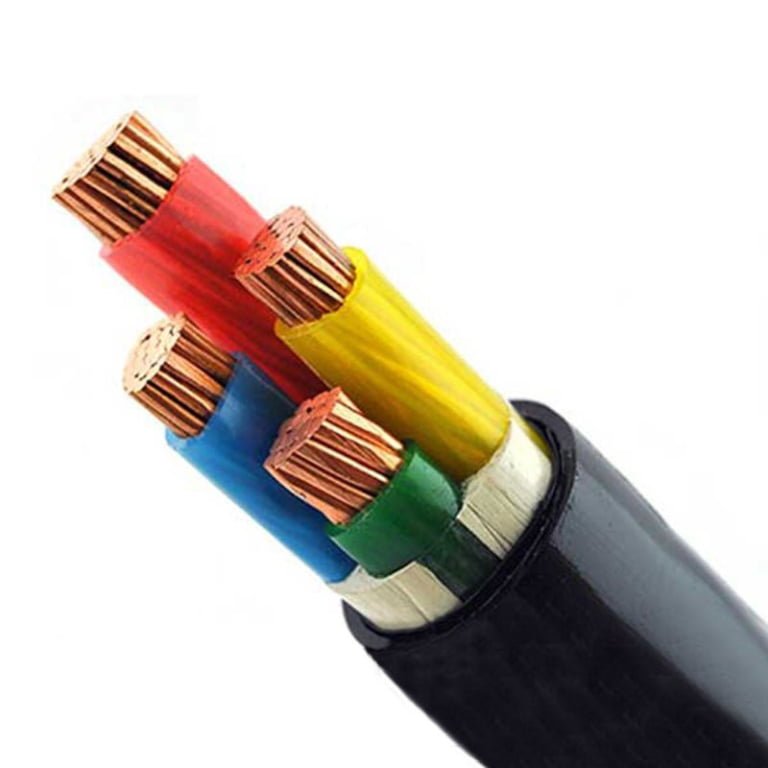
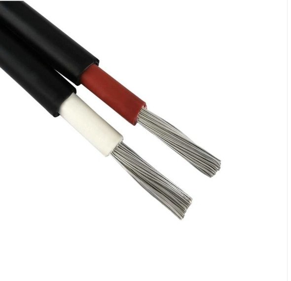
Pulling a cable from an unlabelled conduit run, or inheriting a brownfield site where half the drawings are missing, puts you in a genuinely awkward position. Armoured and unarmoured cables look broadly similar once the outer jacket is the only thing visible, and mistaking one for the other carries real consequences — wrong gland selection leads to water ingress at terminations, incorrect bend-radius assumptions crack the armour wires, and routing an unarmoured cable through a zone that demands mechanical protection is the kind of decision that shows up later as a ground fault mid-shift. The financial hit from a single unplanned outage usually dwarfs whatever time was saved by not verifying the cable type first.
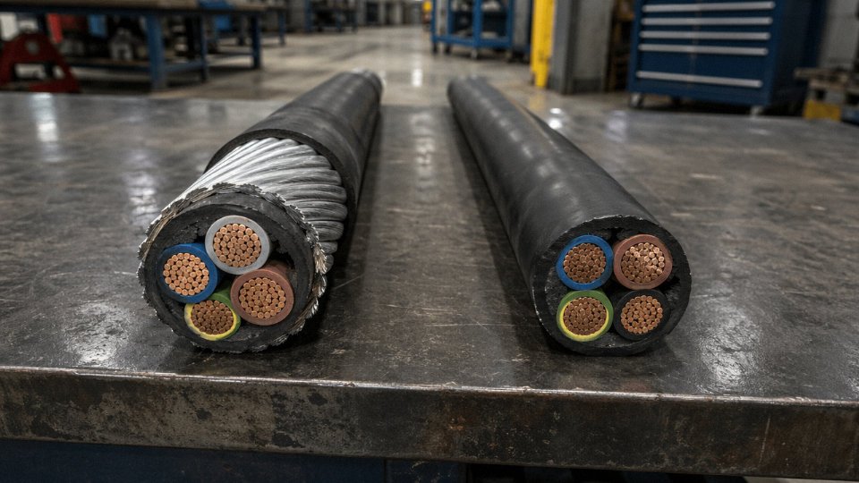
You can tell whether a cable is armoured by checking several physical indicators: a noticeably larger outer diameter (armoured cables typically run 15–40% thicker than unarmoured equivalents of the same conductor size), substantially greater weight per metre, a rigid feel with a large minimum bend radius, visible metallic banding or wire spirals under a cut jacket, and markings on the sheath that include designations such as SWA, AWA, or STA.
What makes this question harder in practice is that not all armour looks the same, and some of the most reliable clues are ones most engineers overlook until they’ve been caught out once. The difference between steel wire armour, aluminium wire armour, and steel tape armour matters for everything from earthing continuity to gland selection to how the cable will behave in a cable tray — and each type has its own set of physical tells.
Understanding the Main Armour Types Before You Inspect
Before you can confidently identify whether a cable is armoured, you need to know what you’re actually looking for. Armour is not a single thing. There are at least five distinct construction types in common industrial use, and confusing them with each other — or with other layers like a metallic screen or a braided shield — causes real procurement and installation errors. A steel tape armour on an instrumentation cable looks nothing like steel wire armour on a 11 kV power cable, and if you’re specifying bend radius or pulling tension without knowing which type you have, the numbers will be wrong.
Steel Wire Armour (SWA)
This is the type most engineers picture when they hear “armoured cable.” Individual round steel wires — typically 0.8 mm to 3.15 mm in diameter, depending on overall cable size and the standard being applied — are wound helically over the inner sheath in a single layer. On a stripped or cut end, it looks like a ring of parallel wires. Along the cable body, that winding pattern creates a distinctive texture: not quite a woven braid, but close enough that some people describe it that way. Run your hand along the cable and you can feel the slight ridging.
SWA is the standard choice for power cables from low voltage up through 33 kV, direct buried or in duct. Wire diameters at the larger end of that range appear on bigger conductor cross-sections — 240 mm² and above — where the armour has to provide meaningful mechanical protection and contribute tensile strength during installation pulls. Smaller cross-sections use finer wire, which is also more flexible.
Steel Tape Armour (STA)
Instead of round wires, STA uses two thin steel tapes wound helically in opposite directions, each overlapping the previous turn by roughly 15–25% of the tape width. The opposing-lay arrangement is what prevents the whole thing from unwrapping. At a cut end, you can see the two tape layers clearly — they look like overlapping metallic ribbons rather than a ring of wires.
STA gives a flatter, smoother outer profile than SWA and adds less overall diameter. It’s common on multicore instrumentation, control, and signal cables where the priority is containment and crush resistance in a trunking or tray environment, not high tensile strength. It’s not the right choice where significant axial load is expected.
Double Steel Wire Armour (DSWA)
Two complete layers of steel wire, wound in opposite directions. Heavier, stiffer, and substantially stronger in tension than single SWA. DSWA is specified for submarine cables, deep-shaft mining cables, and vertical riser applications where the cable must support a significant portion of its own weight over hundreds of metres. If you pick up a DSWA cable, the weight difference is immediately obvious — SWA already runs roughly 1.5–3× heavier per metre than an unarmoured equivalent of the same conductor size, and DSWA adds meaningfully on top of that, depending on wire diameter and the number of conductors.
DSWA cables are required for submarine and vertical riser applications because single-layer SWA cannot reliably withstand sustained axial tensile loads over long vertical runs.True
Single-layer SWA provides tensile support but at sufficient hanging depth the cumulative cable weight exceeds its rated tensile capacity; a second opposing wire layer approximately doubles tensile strength and distributes load more evenly, which is why IEC and project specifications for submarine and mine-shaft cables mandate DSWA.
Aluminium Wire Armour (AWA)
Visually, AWA looks almost identical to SWA at a glance — same helical wire construction, same ridged texture. The differentiator is colour. Steel wires are a dark, slightly dull grey. Aluminium wires are noticeably brighter, silver-grey, closer to what you’d expect from bare aluminium sheet. Once you’ve seen both side by side, it’s hard to confuse them, but in poor lighting or when a cable has been sitting in a dirty trench, the colour difference is less obvious. Scratch the wire surface with a penknife if you’re unsure.
AWA exists specifically for single-core cables — typically larger cross-sections used in high-current power distribution. Steel armour on a single-core AC cable creates a closed magnetic circuit that induces eddy currents, generating heat and representing a measurable efficiency loss. Aluminium is non-ferromagnetic, so it breaks that circuit. If you see a large single-core cable with wire armour, it should be AWA. If it’s steel on a single-core, that’s either an error or a DC application.
Wire Braid Armour and Interlocked Armour
These two are worth knowing because they get misidentified on import documentation and in mixed-standard plants.
Fine-wire braid armour appears on instrumentation and data cables — small-diameter conductors where a braided metallic layer provides both EMI shielding and light mechanical protection. It looks like a textile braid, which is essentially what it is, just in metal. This is not the same as a foil-and-drain-wire screen, though the two are sometimes combined.
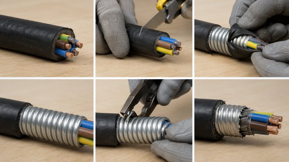
Interlocked armour — more common in North American installations using MC cable construction — is formed from a continuous strip of aluminium (occasionally steel) wound in a tight interlocking helix, creating a flexible conduit-like profile. Each turn mechanically locks into the adjacent one. The appearance is quite different from wire or tape armour: it has a distinct segmented, almost scaly look. This construction is common in commercial building wiring in the US and Canada, and occasionally appears on imported equipment.
Armour Type Comparison
| Armour Type | Material | Appearance | Typical Application | Weight Impact vs Unarmoured |
|---|---|---|---|---|
| Steel Wire Armour (SWA) | Galvanised steel wire | Helical round wires, ridged texture, dark grey | LV/MV power cables, direct burial, duct | +1.5–3× depending on conductor size |
| Steel Tape Armour (STA) | Steel tape | Smooth overlapping ribbon layers, visible at cut ends | Multicore control/instrumentation cables | Moderate — less than SWA |
| Double Steel Wire Armour (DSWA) | Galvanised steel wire (two layers) | Two wire layers, stiff, heavy | Submarine, vertical riser, mine shaft | High — exceeds SWA significantly |
| Aluminium Wire Armour (AWA) | Aluminium wire | Same profile as SWA but silver-grey colour | Single-core LV/MV power cables | Lower than SWA due to aluminium density |
| Wire Braid Armour | Copper or tinned copper, occasionally steel | Fine textile-like braid | Instrumentation, data, signal cables | Minimal |
| Interlocked Armour | Aluminium strip (typically) | Segmented interlocking helix, conduit-like | MC cable, North American commercial wiring | Moderate |
Knowing which type you have changes every downstream decision: termination method, gland selection, bend radius calculation, and whether the armour should be bonded at one end or both. Identifying the armour correctly is the prerequisite for everything that follows.
Step-by-Step Visual Inspection: What to Look for on the Cable Exterior
You don’t always have access to documentation, a cable schedule, or even a legible drum label. In practice, the first thing you do is look at the cable itself. Done systematically, a visual check takes under two minutes and will correctly identify armoured cable in the vast majority of field situations.
Outer Sheath Profile and Rigidity
Start with your hands. Press your thumb firmly into the side of the cable — not a gentle touch, actual sustained pressure. An unarmoured cable will give noticeably; the sheath deflects and the inner core compresses slightly under moderate thumb load. An armoured cable resists this almost completely. The outer sheath sits over a rigid metallic layer, so the whole assembly feels closer to a metal pipe than a rubber hose. SWA cables in particular have a hard, almost unyielding feel even on smaller cross-sections like 4 mm² or 6 mm².
The cross-section profile is another tell. Armoured cables hold a rounder, more uniform shape along their length because the armour wires or tape maintain concentricity. Unarmoured multicore cables, especially flexibles, will often show slight oval distortion where they’ve rested on a surface or been coiled for storage. Armoured cables typically run 15–40% larger in overall diameter than unarmoured equivalents of the same conductor size — the exact figure depends on the armour type and the number of cores, so a 4-core 16 mm² SWA will be noticeably chunkier than a 4-core 16 mm² NYY.
Metallic Glint at Cut Ends or Damaged Sections
Any exposed end — a factory cut, a site trim, a nick from a digger bucket — will show the layer structure clearly if armour is present. Between the outer sheath and the inner bedding you’ll see a distinct metallic layer. The colour tells you something useful about the armour type: steel wire armour looks blue-grey and slightly matte; aluminium wire armour is bright silver and noticeably lighter-looking; corrugated stainless steel tape is silver with visible lateral ridges, almost like a ribbed tube. If you see that metallic band and the cable runs to a panel or duct, there’s armour there.
On damaged sections in service — say, where mechanical damage has split the outer sheath — the same visual clue appears. The outer PVC or XLPE sheath will be split, and underneath it you’ll see either wires or tape rather than a smooth inner sheath going directly to bedding or cores.
Outer Sheath Print Markings
Standards-compliant cables carry printed legends at regular intervals along the outer sheath, typically every 500 mm to 1 m depending on the manufacturer and standard. Look for abbreviations such as SWA (steel wire armour), AWA (aluminium wire armour), STA (steel tape armour), or the word ARMOURED printed in full. IEC and BS-designated cables often include the full designation in the print line — something like BS 5467 or IEC 60502 alongside the conductor size and voltage rating.
Standards-compliant armoured cables must carry sheath markings identifying the armour type at regular intervalsTrue
BS 5467, IEC 60502-1, and similar standards require cable identification markings on the outer sheath, including construction designators such as SWA or AWA, typically repeated at no more than 1 m intervals.
In practice, markings fade on old cables or get obscured by paint, mud, or UV degradation. Don’t rely on markings alone if the sheath is weathered. Treat them as confirmation, not as your primary check.
Gland Entry Points
Walk the cable to where it enters an enclosure, junction box, or switchgear. Armoured cables need a gland designed to grip and earth the armour — typically an A-type or E1W-type brass gland with a compression body, a back-nut, and a separate armour-clamp ring that bites down on the wire or tape layer. If you see a metallic gland with a pronounced two-part body and a back-nut behind the plate, that’s a strong indicator of armoured cable. Unarmoured cables generally use a simpler stuffing gland or plastic cable gland with no armour-clamping feature.
An operational warning: occasionally someone will fit an armoured gland to an unarmoured cable by mistake, or leave a knockout unstuffed. Don’t assume the gland type guarantees armour — use it as one data point alongside the other checks.
Corrugated Metal Sheath vs Wire Armour
On higher-voltage cables, particularly 11 kV and above, you may encounter a corrugated aluminium or corrugated steel sheath rather than individual armour wires. This looks different from SWA — the metal layer is continuous and corrugated like a bellows, not a bundle of distinct wires. It’s still mechanical and electrical protection, but the construction is more like a flexible metallic tube over the insulation system. Don’t mistake the smooth corrugations of a longitudinally welded and corrugated Al sheath for a simple metallic screen — that sheath is load-bearing armour even if it doesn’t look like the classic SWA you’d see on a 0.6/1 kV distribution cable. If you’re looking at a large-diameter cable with a shiny ribbed metallic outer layer directly under a thin overall jacket, that’s almost certainly a corrugated sheath HV cable, and it should be treated as armoured for every practical purpose.
Physical and Dimensional Checks: Measurements That Confirm Armour Presence
Visual inspection gets you most of the way there, but markings fade, sheaths get painted over, and cut ends aren’t always accessible. When you need to be certain — before pulling a cable through conduit, before connecting to a gland, before committing to a trench depth — dimensional and physical measurements give you a definitive answer with tools most site engineers already carry.
Overall Diameter Comparison Against Published Tables
Start with a steel tape or a set of Vernier calipers. Measure the outer diameter at two or three points along the cable, rotating 90° each time — oval cross-sections are common on older cable retrieved from storage, so take the mean. Then look up the nominal unarmoured equivalent in IEC 60502-1 or BS 5467 tables for the same conductor size and configuration.
Armoured cables typically run 3–10 mm larger in overall diameter than their unarmoured counterparts, depending on conductor cross-section and armour type. A 4-core 16 mm² unarmoured cable will typically measure somewhere around 22–24 mm across. The SWA version of the same cable usually comes in at 28–33 mm. That gap is hard to explain any other way. Bedding and sheath tolerances account for maybe 1–2 mm; anything beyond that points to an armour layer sitting between them.
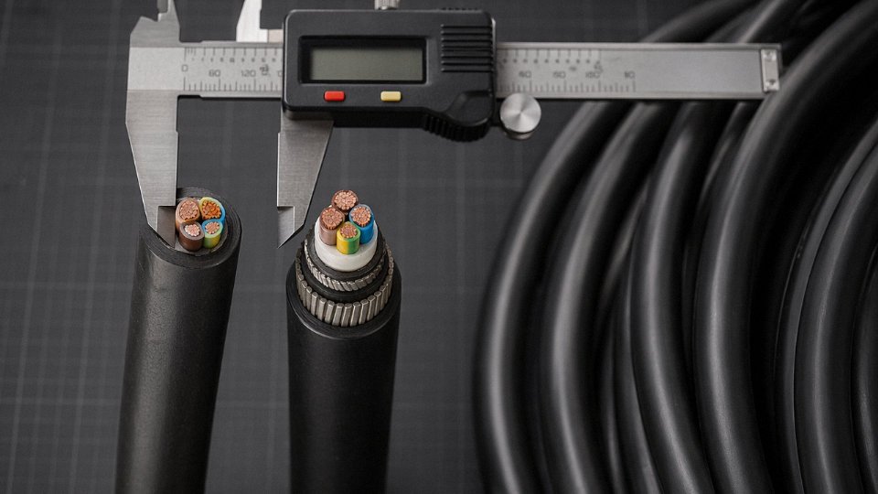
Armoured cables typically add 15–40% to outer diameter compared to unarmoured equivalents of the same conductor sizeTrue
The increase depends on armour type — steel wire armour adds more diameter than steel tape armour, and the proportional impact is larger on smaller cross-sections. This range is consistent with published IEC 60502 and BS 5467 dimensional tables.
Wall Thickness at a Stripped End
If you have access to a cut end — even a short offcut — this is your cleanest confirmation. Strip back the outer sheath carefully and measure the exposed layer thickness with digital calipers. On a properly armoured power cable, you will see a distinct annular layer of steel wires or tape sitting between the inner bedding (usually PVC or XLPE) and the outer sheath. In typical low- and medium-voltage power cables, that layer runs roughly 1–3 mm thick. It is unmistakable once you see it; the wires are laid in a tight helical pattern and the whole assembly feels rigid under the calipers in a way that bedding compound simply does not.
Aluminium wire armour looks similar geometrically but is noticeably lighter to handle and won’t hold a magnetic check (more on that below).
Weight Per Metre as a Cross-Check
Weigh a sample. A 1-metre length cut from the suspect cable, placed on a postal or kitchen scale that reads to 10 g resolution, gives you a fast cross-check. As a rough working example: a 4-core 16 mm² unarmoured cable typically weighs somewhere in the range of 0.6–0.7 kg/m, depending on insulation system and sheath compound. The SWA equivalent of the same cable usually weighs 1.0–1.2 kg/m. That is a roughly 50–70% increase, almost entirely attributable to the steel. If you are looking at a cable and the weight feels unexpectedly heavy for its size, that is worth investigating before you proceed.
SWA cables commonly weigh 1.5–3× more per metre than unarmoured cables at the same conductor cross-section — the multiplier being higher for smaller cable sizes where the armour represents a larger fraction of total mass.
Bending Stiffness: A Qualitative Check That Works
Take a 1-metre sample and try to bend it to a roughly 300 mm radius by hand. Unarmoured flexible cable in the 16–35 mm² range offers moderate resistance and stays bent when you let go. An SWA cable of equivalent conductor size will push back noticeably and spring partially open when released. You are fighting the tensile strength of the steel wires, and it shows. This isn’t a precise test, but on a plant floor at 6 a.m. when you need a quick answer, it tells you something real.
Do not mistake this for the cable being oversized or stiff from cold temperature — a common error in winter when PVC sheaths stiffen up. Check both a known unarmoured and the suspect cable at the same ambient temperature if you can.
Magnetic Response Test for Steel Armour
This one takes thirty seconds and costs nothing beyond a decent rare-earth magnet — the kind used in equipment panels or even a strong refrigerator magnet in a pinch, though a neodymium disc magnet gives cleaner results. Hold or slide it along the outer sheath of the cable. On an SWA or steel tape armoured (STA) cable, you will feel clear, unmistakable attraction through the sheath. The magnet may even track along as you slide it, following the helical wire lay.
Aluminium wire armour (AWA) produces no magnetic response at all. Neither does an unarmoured cable. So a negative result here does not rule out armour — it rules out steel armour specifically, which matters when you are selecting glands or planning earthing continuity.
One operational warning: on cables with a thick outer sheath — typically 3 mm or above — a weak magnet may give an ambiguous response. Use the strongest magnet available, and test on a known SWA cable first to calibrate your expectation for that sheath thickness.
Reading Cable Markings, Drum Labels, and Documentation
When markings are intact, this is your fastest and most reliable identification route. Physical inspection tells you something is there; the marking system tells you exactly what it is.
Decoding the Cable Designation Code
IEC 60502 and BS 5467 both use a structured alphanumeric code printed along the outer sheath, usually repeating every 500–1000 mm. Take a typical example:
4×95 mm² 0.6/1 kV XLPE/SWA/PVC
Breaking that down field by field:
- 4×95 mm² — four conductors, each 95 mm² nominal cross-section
- 0.6/1 kV — rated 0.6 kV conductor-to-earth, 1 kV conductor-to-conductor
- XLPE — cross-linked polyethylene insulation
- SWA — Steel Wire Armour (this is the armour designator)
- PVC — outer sheath material
The armour designator sits between the insulation and the outer sheath codes. Common armour abbreviations you’ll encounter: SWA (steel wire armour), AWA (aluminium wire armour), STA (steel tape armour), DSTA (double steel tape armour). If that third field reads something like OS or SC, that’s a screen or separator — not armour. The distinction matters because screened unarmoured cables get misidentified as armoured more often than you’d expect, particularly on instrumentation cables where both a screen and a heavier outer sheath can look convincingly robust.
SWA in a cable designation always indicates mechanical armour, not an electrical screenTrue
Under IEC 60502 and BS 5467, SWA specifically denotes steel wire armour as a mechanical protection layer; screens are designated separately (e.g., OS for overall screen), so the two cannot be confused within a correctly printed designation code
Reading a Drum Label Field by Field
A standard IEC-compliant drum label carries more information than most people bother to read. Typical fields include: manufacturer name and factory code, cable type designation (the full code above), number and cross-section of conductors, voltage rating, applicable standard (e.g., BS 5467, IEC 60502-2), overall nominal diameter, drum length, gross and net weight, and a drum or reel serial number.
For armour identification specifically, look at the cable type field — the SWA, AWA, or STA designator will appear there explicitly. The overall diameter field also matters: if you already know the unarmoured equivalent’s diameter from a datasheet, an increase of roughly 15–40% (depending on conductor size and armour type) is a reasonable cross-check. A 4×95 mm² unarmoured cable might run around 32–35 mm overall; the SWA version of the same cable will typically sit closer to 42–47 mm, though exact figures depend on the manufacturer’s construction and sheath tolerances.
Weight per drum is another useful cross-check. SWA cables run roughly 1.5–3× heavier per metre than unarmoured equivalents at the same conductor cross-section — the upper end of that range applies to smaller conductors where the armour steel represents a larger proportion of total mass.
Test Certificates and Factory Documentation
IEC-compliant manufacturers issue a Routine Test Certificate against each drum. For armoured cables, the certificate should explicitly state armour wire nominal diameter, armour lay length, and the DC resistance of the armour layer. If you’re procuring from an unfamiliar supply chain, request these certificates before the cable ships — not after it arrives on site. A certificate that lists insulation resistance and voltage test results but says nothing about armour parameters is either incomplete or the cable isn’t actually armoured.
On larger projects, the factory test certificates should be cross-referenced against the approved drawing package. Discrepancies between the certificate and the drum label are uncommon with established manufacturers but do occur with sub-contracted production runs.
North American and Legacy Marking Conventions
Not all supply chains follow IEC conventions. Under NEC and UL standards, armoured cables carry designations like MC (Metal-Clad cable), AC (Armoured Cable, sometimes called BX informally), or TECK90 (a Canadian standard for armoured control and power cable). These use interlocked metal tape or continuous corrugated armour rather than individual steel wires, so the construction looks quite different from SWA even though the protective function is similar.
Older British Standard cables — pre-harmonisation, pre-BS 5467 — may carry designations like PILCSWA (paper-insulated lead-covered steel wire armoured) or simply stamped markings that differ from modern IEC formats. If you’re pulling cable from a building constructed before roughly the mid-1980s in the UK, expect inconsistent or partially degraded marking conventions. European harmonised HD cables use a different alphanumeric prefix system (H, A, or national designations) and you’ll need IEC 60228 and the HD 361 harmonisation documents to decode them fully.
When Markings Are Missing or Illegible
UV degradation, mechanical abrasion, chemical exposure, and plain old age all eat sheath printing. A cable that’s been installed outdoors without UV-stabilised sheathing for fifteen or twenty years can lose its markings almost entirely. In that situation, don’t guess — fall back to the physical and dimensional inspection methods covered earlier in this article, and cross-reference with installation records, as-built drawings, or the original purchase order. If the project was specified under a particular standard, the spec document itself may identify cable types by circuit or zone, which narrows your search considerably.
One practical habit worth building: photograph drum labels before installation and file them against the cable circuit reference. It takes thirty seconds per drum and has saved significant diagnostic time during fault investigations more than once.
Identifying Armoured Cable in Installed Conditions: Trenches, Trays, and Conduits
Once a cable is in the ground or bundled into a tray with thirty others, the identification problem gets harder. You can’t always see the sheath markings, the drum is long gone, and nobody on the current site crew was there for the original installation. This situation is common — and the adapted approach depends heavily on where the cable is installed.
Direct-Buried Cables
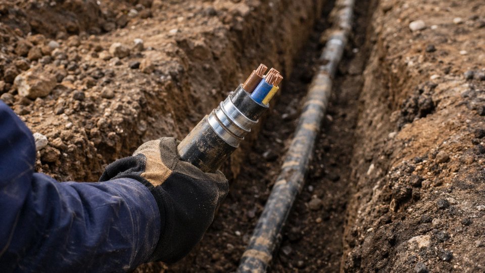
Excavating around an unknown buried cable is one of the more anxiety-inducing jobs on a brownfield site. Here’s a useful heuristic: armoured cables are routinely direct-buried without a protective duct precisely because the armour is the mechanical protection. If you dig down and find a cable sitting in native soil or sand bedding with no duct or conduit around it, that’s a reasonable first indicator you’re looking at armoured construction. Unarmoured cables buried without conduit do exist — usually the result of past shortcuts — but it’s not compliant practice under most installation standards.
Look for warning tape 200–300 mm above the cable run. Its presence doesn’t confirm armour, but combined with a duct-free installation it strengthens the case. Once you have a short exposed section, grip the cable firmly and try to flex it. SWA cable in a typical medium-voltage or multicore power size resists bending noticeably — you can feel the wire armour layer pushing back. An unarmoured cable of similar conductor cross-section will flex with far less resistance.
Cable Tray and Ladder Installations
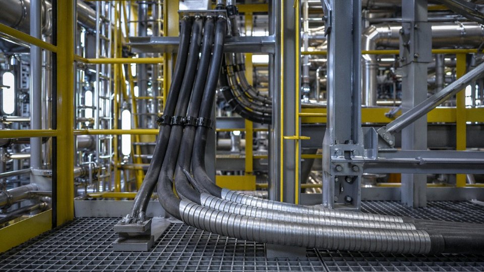
Open cable trays are actually the easiest installed environment for identification. SWA cables hold their circular profile along the full run — they don’t sag between tray supports, they don’t flatten or ovalize, and they maintain a consistent lay. Run your hand along the sheath and you’ll feel that characteristic corrugated or slightly textured surface from the wire layer underneath, even through an outer PVC oversheath.
Look at the termination glands. Armoured cables — almost without exception in a properly executed installation — terminate into metallic SWA glands, either brass or stainless, with a locknut on the equipment side and a clamping ring that bites onto the armour wires. These are physically distinct from plain cable glands. The gland body is larger in diameter relative to the cable, and you’ll usually see the armour wires fanned out and trapped under the clamping cone.
Unarmoured flexible cables on the same tray behave completely differently: they drape between supports, develop a slight flatten under their own weight on longer spans, and terminate into plain compression glands with no armour clamping feature.
Conduit Installations
Finding armoured cable inside conduit is unusual. It happens on rework jobs where someone pulled new armoured cable through an existing conduit run — often because that was the cable available, or because a specification changed mid-project. The giveaway is the gland: a metallic SWA gland at the conduit entry is a reliable indicator. The cable will also fit the conduit very tightly, leaving minimal annular space, because armoured cables run 15–40% larger in outer diameter than unarmoured equivalents of the same conductor size (the actual increment depends on armour wire diameter and the number of conductor cores). Pulling unarmoured cable through conduit is straightforward with basic lubricant; an armoured cable in the same conduit will be nearly impossible to move without significant force, or won’t have been pullable at all — which sometimes explains why the conduit end was just sealed and abandoned.
Partial Exposure at Joints and Terminations
Buried joint bays and in-line splices are worth examining when accessible. A properly made joint on an armoured cable includes armour continuity — typically a green-yellow earth conductor soldered or mechanically clamped to the armour at each side of the joint, then bonded through the joint body. You’ll see this earth tail exiting the joint sleeve and connecting to an earth terminal or the cable’s own earth core. That bonding hardware is mechanically distinct from a simple cable joint on unarmoured cable, which has no such feature.
The presence of a green-yellow earth conductor bonded to exposed armour wires at a cable joint confirms the cable is armoured and that armour continuity has been maintained through the joint.True
Armour continuity bonding is required by IEC and BS 7671 standards to ensure the steel wire armour functions as a protective conductor; this bonding is physically absent on unarmoured cable joints, making it a reliable visual discriminator.
Thermal Imaging as a Non-Invasive Check
Under operating load, a correctly installed and bonded SWA cable produces a remarkably uniform thermal profile along its length when viewed with an infrared camera. The armour layer distributes heat evenly and the earthed steel acts as a partial heat sink. Where armour bonding is broken or missing — a cut earth tail, a corroded gland, a joint where the armour continuity bond was omitted — you’ll see a localised warm patch, typically at the termination or joint location. In practice this technique is more useful for confirming armour bonding quality than for confirming armour presence, but on a live system where you can’t touch anything, a cable showing that characteristic thermal evenness is likely armoured and properly bonded. A dramatic hot spot at a gland, on the other hand, is a warning that something is wrong with the armour earth path regardless of cable type — and that should be flagged for immediate investigation rather than just logged.
Common Misidentifications and How to Avoid Them
Getting this wrong doesn’t just cause confusion on the drawing — it causes failures in the field. A cable that looks armoured but isn’t will be routed through a rocky trench or clamped directly to steelwork, and six months later you’re digging it back up. These are the misidentifications that actually happen, repeatedly.
Screened Cable Mistaken for Armoured Cable
This is probably the most common error, especially with multi-core instrumentation and control cables. A copper braid or aluminium-foil screen underneath the outer sheath catches the light, feels metallic, and looks — at a cut end — vaguely like a layer of armour. It isn’t.
The functional difference is fundamental. A screen exists to manage electromagnetic interference. It’s electrically continuous but mechanically almost irrelevant — copper tape screens are typically 0.05–0.15 mm thick, aluminium foil even thinner. Apply a point load from a cable clamp edge or a sharp stone in backfill, and the screen collapses or tears entirely. Armour wires (SWA, typically 1.6–3.15 mm diameter for low-voltage power cables depending on cable diameter and standard) are structural. They’re there to resist crush, tension, and abrasion.
If you cut back an outer sheath and see a layer of fine, loosely-woven bright copper wire or a thin foil wrap, that’s a screen. Armour wires, by contrast, are stiff, individually distinct, and visibly substantial — you can get a fingernail under a single wire without difficulty.
Corrugated Metal Sheath vs Wire-Over-Bedding Armour
Medium and high-voltage cables quite often have a corrugated aluminium or steel sheath extruded or formed directly over the insulation system. From a distance, particularly in a cable tray, this can look similar to a corrugated-bedding armoured cable. It isn’t the same construction at all.
Corrugated sheaths have no individual wire lay — run your hand along the cable and you feel a seamless, rippled profile with no helical pitch or wire-gap texture. The corrugations are integral, formed continuously. SWA and STA (steel tape armour) constructions have a distinct helical wire lay or tape overlap pattern that you can feel and see. The corrugated sheath is typically the moisture and radial-stress barrier on an MV cable, and it’s often combined with separate armour underneath, or used without armour depending on installation duty. Don’t assume either way — check the drum documentation.
Flexible Metallic Conduit Is a Raceway, Not Armour
This distinction matters most during installation inspections and when inheriting someone else’s plant. Flexible metallic conduit (FMC) — the interlocked galvanised steel or aluminium strip product used at machine connections, panel drops, and vibrating equipment terminations — is a wiring raceway. The cables inside it are almost always standard unarmoured cables. The conduit provides mechanical protection, but it is not listed or rated as cable armour, and in most jurisdictions it cannot substitute for it.
Flexible metallic conduit provides equivalent mechanical protection to steel wire armoured cable for direct burial applications.False
FMC is a raceway product, not a cable armour construction. It is not rated for direct burial, lacks the tensile and crush resistance of SWA, and the cables inside remain unarmoured. Treating FMC as equivalent armour for burial or heavy mechanical exposure applications is a code violation in most standards and a genuine failure risk.
If you’re commissioning an installation and see FMC running to a piece of equipment, the cables inside need to be identified separately. Don’t record the circuit as armoured.
Steel Wire Braid on Instrumentation Cables
Some higher-specification instrumentation cables — particularly those used in petrochemical or process control environments — include a steel wire braid layer that functions as both a screen and a degree of light mechanical protection. This is not SWA. The wire diameter is finer, coverage is typically 60–85%, and there’s no bedding layer separating it from the conductors in the way a proper power cable armour construction would have.
These cables are not suitable for direct burial without additional protection, not suitable for applications requiring the tensile and crush resistance of true SWA, and must not be scheduled as such in cable schedules or procurement documents. In practice, the confusion usually happens when an instrumentation contractor’s cable gets substituted or an unfamiliar engineer reads “steel wire” in the description and assumes equivalence.
Degraded Outer Sheath Exposing Armour
UV degradation, solvent contact, or mechanical abrasion can cause a PVC outer sheath to crack, peel, and pull back — exposing the armour layer underneath. On an older cable in an outdoor tray or near a chemical spill area, this can look exactly like deliberate strip-back at a termination point, especially if it’s happened gradually over several years.
Exposed armour without an intact outer sheath is not a cable in acceptable condition. The sheath is there to protect the armour from corrosion and to maintain the cable’s IP rating; once it’s gone, steel wire armour corrodes faster than most people expect, particularly in wet or coastal environments. This isn’t a “monitor it” situation — it requires immediate repair with an appropriate cable repair sleeve or section replacement. Mistaking it for normal termination strip-back and walking past it is how a cable fails quietly until something trips.
Practical Identification Toolkit: Tools, Standards, and a Decision Flowchart
By the time you’ve worked through visual inspection and sheath markings, you usually have a strong working hypothesis. But “strong hypothesis” isn’t good enough before you order a gland, set a bending radius, or sign off an installation. This section pulls everything into one repeatable procedure.
The Recommended Tool Kit
You don’t need a lab. A basic kit that fits in a medium site bag covers the vast majority of identification scenarios:
- Digital vernier calipers, 0–150 mm — the workhorse. Cheap, fast, and gives you the overall diameter you need to cross-reference standard tables.
- Rare-earth disc magnet — a neodymium button magnet from any electronics supplier works fine. SWA and STA both respond; aluminium wire armour (AWA) does not. The test takes roughly five seconds and costs nothing.
- Pocket knife — for a careful, shallow nick on the outer sheath only, enough to expose a cross-section without damaging inner layers. Practice the depth on scrap first.
- Portable hanging or postal scale — weigh a cut metre and compare against manufacturer data sheets or standard tables. Armoured cable typically runs 1.5–3× heavier per metre than an unarmoured equivalent of the same conductor cross-section; exactly where in that range depends on conductor material, armour wire gauge, and bedding thickness.
- Infrared thermometer or compact thermal camera — essential when the cable is live and you cannot touch it safely. Temperature differentials in the sheath can also hint at loading status, which matters if you’re trying to identify a cable that should be de-energised before gland work.
- UV torch (365 nm) — faded print on aged black HDPE sheaths sometimes fluoresces under UV, recovering characters that look completely gone in white light. Underrated tool on old installations.
- Printed or digital copies of IEC 60502-1, IEC 60502-2, BS 5467, BS 6724 — specifically the dimensional tables. Cross-referencing a measured diameter against these tables is often decisive.
Decision Flowchart Logic
Run the steps in sequence. Stop as soon as you have a confirmed answer — there’s no value in completing every step once you’re certain.
Step 1 — Sheath markings. Read the printed legend. IEC and BS cables print construction type in the designation (e.g., SWA, AWA, or the numeric IEC code). If legible and consistent, that’s your answer.
Step 2 — Magnet test. If markings are absent or suspect, hold the neodymium magnet against the outer sheath. Attraction confirms ferrous armour (steel wire or steel tape). No attraction means either AWA, non-armoured, or a screened cable — proceed to Step 3.
Step 3 — Measure overall diameter. Caliper across at least three points and average. Compare to dimensional tables in IEC 60502-1 (LV up to 1 kV) or IEC 60502-2 (MV 3.6/6 kV to 20.8/36 kV). Armoured cables typically run 15–40% larger in outer diameter than unarmoured equivalents for the same conductor — the spread depends on conductor cross-section and armour type, so use the actual tables, not that rough rule alone.
Step 4 — Cut end or gland entry inspection. If a gland entry is accessible, look for a visible metallic layer beneath the outer sheath. SWA shows individual round wires; STA shows a smooth helical tape overlap; AWA looks like SWA but silver-grey rather than bright or black-oxide steel.
Step 5 — Drum label and documentation. Shipping drum labels carry the full type designation, manufacturer part number, and usually a reference to the applicable standard. Test certificates, if available, settle any remaining doubt.
Step 6 — Contact the manufacturer. If you’re still uncertain after Step 5, don’t guess.
Standards Reference Table
| Standard | Scope | Where Armour Requirements Sit |
|---|---|---|
| IEC 60502-1 | LV power cables ≤ 1 kV | Clauses 12–13: armour construction and materials; Annex dimensional tables |
| IEC 60502-2 | MV power cables 3.6/6 kV – 20.8/36 kV | Clauses 14–15: armour; dimensional requirement tables throughout |
| BS 5467 | LV armoured cables with thermosetting insulation (UK) | Clause 8: armour; Table 4 onwards for dimensions |
| BS 6724 | LV armoured cables, low-smoke zero-halogen sheath (UK) | Mirrors BS 5467 structure; sheath compound differences in Clause 9 |
| IEC 60228 | Conductors for insulated cables | Cross-section classes and resistance — use to confirm conductor sizing when markings are gone |
| ASTM B8 | Concentric-lay-stranded copper conductors (US) | Referenced when verifying conductor construction in North American-spec cables |
When to Call the Manufacturer
Provide as much of the following as you can — a technical team can usually narrow things down significantly if you give them: overall diameter (averaged from three caliper measurements), conductor count and approximate cross-section, outer sheath colour and any visible intermediate layer colours, measured weight per metre of a cut sample, and clear photographs of the cable body and any cut ends. Photographs of the cut end cross-section are worth more than almost any other single piece of information.
A rare-earth (neodymium) disc magnet can reliably distinguish ferrous-armoured cables from AWA or unarmoured cables through the outer sheath without any sheath damage.True
Steel wire and steel tape armour are ferromagnetic; a neodymium magnet will attract to them through a typical PVC or XLPE outer sheath. Aluminium wire armour is non-ferromagnetic and produces no attraction. This is a well-established site test used by installation engineers and verified by basic material science.
Documentation After Identification
Once identified, label both ends with durable heat-shrink or engraved aluminium cable markers — adhesive labels peel off in a couple of seasons in most industrial environments. Add markers at any junction box entry, at both sides of any penetration, and at intervals of roughly 15–25 m on long runs (the specific spacing usually comes down to project spec or client preference). All identification findings should go into the project as-built record: cable type confirmed, identification method used, date, and the name of whoever carried out the check. Sounds bureaucratic, but the next engineer who pulls that cable out of a crowded tray at 2 a.m. will appreciate it.
Armoured Cable Selection Criteria: Choosing the Right Type for Your Application
Once you’ve confirmed a cable is armoured — or you’re specifying from scratch — the next question is whether the right armour type is actually being used. This is where a lot of procurement errors happen. The identification work above is wasted if the replacement or extension cable ends up with a different armour construction than the original design specified.
Mechanical Load Classification: Match the Armour to the Stress
SWA (Steel Wire Armour) covers the majority of direct-burial power distribution work. It handles incidental tensile loads from backfill settlement and minor ground movement well enough, and it’s available almost everywhere. For most LV feeder runs in industrial sites or utility distribution — say, a 150 mm² 4-core buried at 700 mm depth in compacted clay — SWA is the practical default.
DSWA (Double Steel Wire Armour) is a different conversation. The moment you’re pulling cable down a vertical riser shaft longer than about 20–25 m, or spanning an overhead section, or working on a submarine route with bottom currents and anchor hazard, tensile loads become the governing design parameter rather than crush resistance. DSWA roughly doubles the steel cross-section, and when sustained tensile loads exceed roughly 5 kN — which depends on cable weight, span length, and dynamic loading — single-layer SWA armour wires can yield or pull through at the gland. That failure mode is quiet and slow, which makes it worse.
STA (Steel Tape Armour) is often misunderstood. The interlocked or overlapping steel tapes give good radial crush resistance in a cable tray environment, and for multicore instrumentation cables running alongside process pipework where someone might drop a wrench or route-around with a pry bar, STA does that job efficiently. What it does not do well is resist sustained tensile load — the tape construction isn’t designed for it. Don’t specify STA on anything that hangs.
Single-Core AC Cables: The AWA Rule Above 16 mm²
For single-core AC power cables above roughly 16 mm² conductor cross-section, SWA is the wrong choice. The physics are straightforward: a continuous steel armour loop around a single AC conductor creates a shorted secondary winding. The alternating magnetic field from the conductor induces circulating currents in the armour, and those currents generate heat — at 95 mm² or above, the thermal losses can be significant enough to derate the cable materially or, in a badly ventilated installation, cause premature insulation degradation. AWA (Aluminium Wire Armour) breaks this problem because aluminium’s lower permeability dramatically reduces induced losses while still providing mechanical protection.
SWA single-core armour creates circulating current losses on AC circuits above approximately 16 mm² conductor cross-sectionTrue
Steel's ferromagnetic properties create a near-complete magnetic circuit around the conductor. IEC 60502 and most national standards require non-magnetic armour for single-core AC cables above this threshold precisely because of measurable circulating current losses.
In practice, single-core SWA turns up on site more often than it should, usually because someone ordered the wrong cable or a supplier substituted. Check your drum labels before the cable goes in the ground.
Environmental and Chemical Resistance
Standard galvanised SWA corrodes in chloride-rich environments — offshore platforms, coastal substations, chemical plants running chlorinated process streams — faster than most installation schedules account for. SSWA (Stainless Steel Wire Armour) costs more upfront, typically adding another 10–20% on top of standard SWA pricing depending on wire diameter and stainless grade, but in a marine atmosphere the service life difference can be measured in decades rather than years.
Alkaline soil is a separate issue. High-pH ground conditions, particularly around concrete-heavy civil construction or sites with industrial alkaline waste, attack galvanised steel through the zinc protective layer. Aluminium armour handles alkaline environments better, though it’s not immune to chlorides — so on a coastal site with alkaline backfill you’re usually looking at SSWA or a heavily oversheathed SWA with verified polyethylene outer sheath integrity.
Voltage Class Alignment
Armour options aren’t identical across voltage classes, and the bedding and oversheath requirements change too. LV cables up to 1 kV fall under IEC 60502-1, where armour is applied directly over the laid-up cores with an inner sheath beneath. MV cables from 3.6/6 kV through 18/30 kV are covered by IEC 60502-2, which mandates a more robust bedding arrangement and tighter dimensional controls on armour wire lay length. HV cables above 36 kV operate under IEC 60840, and at that voltage class the armour specification interacts with the metallic screen design — getting this wrong in procurement isn’t a minor paperwork issue, it’s a factory test failure.
Cost and the Honest Procurement Question
SWA typically adds somewhere in the range of 20–35% to cable cost compared to an equivalent unarmoured cable, depending on current steel wire prices, conductor size, and number of cores — the percentage is larger on small cables where the armour represents a bigger share of total material cost. AWA adds less in raw material terms but introduces stricter installation requirements around gland selection and earthing continuity.
The genuine procurement question is whether that premium is justified. For cable runs in trunking, in rigid conduit, or inside a fully enclosed cable duct where mechanical damage is essentially impossible and the route won’t be disturbed, an unarmoured cable at lower cost often makes more engineering sense. The armour premium earns its keep on direct-buried runs, exposed industrial environments, or anywhere route protection cannot be guaranteed for the cable’s intended 25–40 year service life.
Frequently Asked Questions About Armoured Cable Identification
Can I identify armoured cable without cutting into it?
Yes, and in most site situations you should avoid cutting just to confirm armour presence. The printed sheath code is your first resource — look for designations like SWA, AWA, or STA in the cable description embossed or printed along the outer jacket. If the markings are worn, run a strong rare-earth magnet along the cable surface: steel wire armour will pull the magnet noticeably, aluminium wire armour will not react at all. Dimensional comparison is another non-destructive route — measure the overall diameter with calipers and cross-reference against the manufacturer’s published tables; an unexplained diameter increase of roughly 15–40% over the expected unarmoured equivalent (depending on conductor size and armour type) is a strong indicator. At gland entry points or termination boxes, the armour wires are usually partially exposed and visible without any cutting at all. Between the magnet test, dimensional check, and gland inspection, you can make a reliable call in the field without touching a blade to the cable.
Is all black-sheathed cable armoured?
No. This is one of the most persistent misconceptions on site. A large proportion of unarmoured cables — single-core building wire, unarmoured multicore flexibles, screened instrumentation cable — ship with black PVC or LSZH outer sheaths as standard. Sheath colour is a commercial convention, not a structural indicator. Always read the printed marking first. If the print is gone, apply the physical tests — weight, diameter, and the magnet check.
Does armoured cable need a separate earth conductor?
For SWA cables, the steel armour can legally serve as the circuit protective conductor provided its cross-sectional area meets the requirements of IEC 60364-5-54 — which it usually does for larger conductor sizes, but may not for smaller cross-sections where the armour wire count and diameter are limited. In practice, many contractors and plant electricians add a separate green-yellow earth conductor regardless, partly for belt-and-braces continuity and partly because local inspection authorities or client specs demand it. Industrial sites with heavy vibration or frequent gland disturbance are especially worth fitting with a dedicated earth: armour continuity through glands degrades over time if the glands loosen.
The SWA armour on a correctly terminated and earthed cable can serve as the circuit protective conductor under IEC 60364-5-54 without a separate earth wire.True
IEC 60364-5-54 explicitly permits metallic armour as a protective conductor where the impedance and cross-sectional area are adequate. This is standard practice in many European industrial installations, though local amendments and client specifications may require an additional earth conductor.
How do I tell SWA from AWA at a cut end?
SWA wires are dark grey with a dull zinc-coated surface — they look like galvanised steel, because that is what they are. AWA wires are noticeably brighter, more silver-white, and feel meaningfully lighter when you handle a cut length. For the same overall cable diameter, an AWA cable can be 30–50% lighter per metre than the SWA version, which matters a lot when pulling through trays or ordering lifting equipment for drum handling. The magnet test settles any remaining doubt in about two seconds.
Can armoured cable be used indoors?
Routinely. SWA and steel tape armoured (STA) cables are standard in indoor industrial environments — motor rooms, switch rooms, cable basements — wherever mechanical damage risk justifies the extra cost and termination effort. The armour must be properly earthed at both ends through appropriate cable glands; skipping this turns the armour into a floating conductor, which is a shock and EMI hazard. In commercial buildings or public spaces, LSZH-sheathed SWA variants are the right choice because standard PVC sheaths produce heavy smoke and toxic gases in a fire.
What does armour add to overall cable weight and diameter?
For a typical 4-core 35 mm² LV power cable, SWA adds roughly 2.5–4 mm to the overall diameter and increases weight per metre by somewhere in the 40–60% range compared to the unarmoured equivalent. Those figures depend on armour wire diameter (which scales with conductor size), the number of wires in the helical layer, and bedding thickness. Always pull the manufacturer’s actual data sheet — estimated figures are fine for planning but not for conduit sizing or structural cable tray load calculations.
How do I verify armour specification from a new supplier?
Ask for the factory Routine Test Certificate covering dimensional checks — specifically armour wire diameter, lay length, and coverage — against IEC 60502-1 or BS 5467 tables. Type test reports from an accredited laboratory confirm the armour construction meets the standard, not just the supplier’s internal spec. For any meaningful volume order, specify third-party factory inspection and, if the project schedule allows, witness testing at the manufacturing facility. Reviewing the actual armour wire spool labels against the certificate during a factory visit catches substitution early, before the cable is on a ship. A supplier who resists third-party inspection on a large order is telling you something worth paying attention to.
Conclusion: Building a Reliable Cable Identification Practice
By the time you’ve worked through a full inspection — sheath markings, physical measurements, cut-end examination, and documentation — you should have converged on a confident answer. If you haven’t, that’s actually useful information: it tells you the cable has been relabelled, re-drummed, or damaged enough that single-method identification is genuinely unreliable. That situation calls for a second opinion, not a guess.
The identification hierarchy that runs through this entire article is worth committing to habit. Start with the sheath print — it’s the fastest check and, when legible, the most unambiguous. A clear “SWA,” “AWA,” or IEC-format type designation printed every metre or so along the outer sheath should be your first stop. If that’s degraded or absent, reach for a magnet. Steel wire or steel tape armour will respond noticeably; aluminium wire armour won’t. Neither will a copper screen, which is where a lot of misidentifications originate. Third, do the dimensional check: an armoured cable of a given conductor cross-section will run noticeably heavier and thicker than its unarmoured equivalent — often 1.5 to 3 times the per-metre weight for SWA, and 15 to 40% larger in outer diameter depending on armour construction and conductor count. If you have calipers and a short cut length, use them. Fourth, inspect a cut end under decent light. Armour wires or tapes sit as a distinct concentric layer between the inner and outer sheaths; a screen is a thin, loosely applied foil or braid sitting directly against the insulation cores. They look completely different once you know what you’re looking at. Fifth, pull the drum ticket, the delivery note, or the test certificate. A legitimate cable shipment should carry IEC or BS test records that name the construction explicitly. Finally, if none of that resolves the question cleanly, call the manufacturer.
Use at least two methods before making a final determination. That’s not bureaucratic caution — it reflects how real misidentifications happen. In practice, a single passing check on a faded sheath print has sent armoured cable into a trunking system sized for unarmoured, forcing a reroute mid-project. Conversely, a heavy corrugated thermoplastic outer sheath has been mistaken for steel tape armour, and the cable ended up direct-buried without the mechanical protection the design assumed. Both failures were avoidable with a second check.
Mis-specifying or misidentifying armoured cable in a completed installation can constitute a code violation under IEC 60364 or NEC Article 300, potentially invalidating site insurance and creating personal liability for the responsible engineer.True
IEC 60364-5-52 and NEC Article 300 both specify wiring method and cable type requirements for installation environments. Installing an unarmoured cable where the design calls for armoured — or vice versa — can breach the wiring method requirements, which affects both code compliance and insurance validity.
This is a safety and compliance issue, not a technicality. The consequences of getting it wrong include shock and fire risk from mechanical damage to an unprotected cable, code violations under IEC 60364 or NEC installation rules, and insurance liability that falls directly on the specifying engineer or installing contractor. Regulators and insurers do not typically accept “the markings were unclear” as mitigation once an incident has occurred.
Jinda has been manufacturing armoured cables since 1987 — SWA, AWA, steel tape, and specialty constructions — across five production bases and supplying to customers in more than 50 countries. The engineering team can provide full dimensional datasheets, IEC-compliant test certificates, and construction cross-sections for any cable in the range, which is exactly the kind of documentation that makes the identification hierarchy above straightforward rather than frustrating. If you’re working through a project specification, sourcing for bulk supply, or simply need to verify whether an existing cable type matches your application, contact Jinda’s technical team directly. Samples, specifications, and application guidance are available without the usual procurement friction.